Page 729 of 1449

INTAKE AND EXHAUST -Turbocharger15-23
DISASSEMBLY SERVICE POINTS
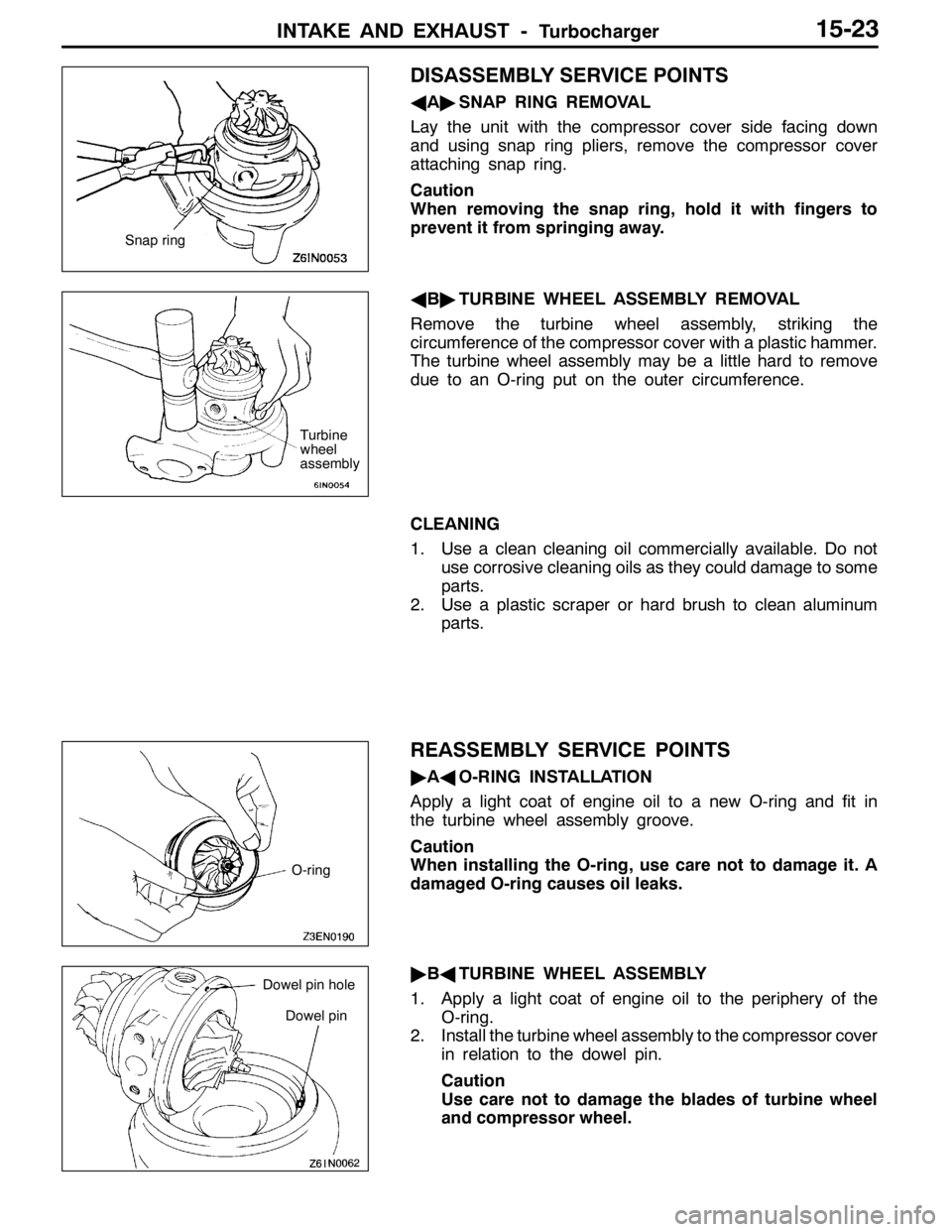
AA"SNAP RING REMOVAL
Lay the unit with the compressor cover side facing down
and using snap ring pliers, remove the compressor cover
attaching snap ring.
Caution
When removing the snap ring, hold it with fingers to
prevent it from springing away.
AB"TURBINE WHEEL ASSEMBLY REMOVAL
Remove the turbine wheel assembly, striking the
circumference of the compressor cover with a plastic hammer.
The turbine wheel assembly may be a little hard to remove
due to an O-ring put on the outer circumference.
CLEANING
1. Use a clean cleaning oil commercially available. Do not
use corrosive cleaning oils as they could damage to some
parts.
2. Use a plastic scraper or hard brush to clean aluminum
parts.
REASSEMBLY SERVICE POINTS
"AAO-RING INSTALLATION
Apply a light coat of engine oil to a new O-ring and fit in
the turbine wheel assembly groove.
Caution
When installing the O-ring, use care not to damage it. A
damaged O-ring causes oil leaks.
"BATURBINE WHEEL ASSEMBLY
1. Apply a light coat of engine oil to the periphery of the
O-ring.
2. Install the turbine wheel assembly to the compressor cover
in relation to the dowel pin.
Caution
Use care not to damage the blades of turbine wheel
and compressor wheel.
Snap ring
Turbine
wheel
assembly
O-ring
Dowel pin
Dowel pin hole
Page 733 of 1449

16-1
ENGINE
ELECTRICAL
CONTENTS
CHARGING SYSTEM 2................
GENERAL INFORMATION 2................
SERVICE SPECIFICATIONS 3...............
SPECIAL TOOL 3..........................
ON-VEHICLE SERVICE 4...................
Alternator Output Line Voltage Drop Test 4......
Output Current Test 5........................
Regulated Voltage Test 7.....................
Waveform Check Using An Analyzer 8..........
ALTERNATOR 10..........................
STARTING SYSTEM 17................
GENERAL INFORMATION 17...............
SERVICE SPECIFICATIONS 17..............
ON-VEHICLE SERVICE 18..................
STARTER 18..............................
IGNITION SYSTEM 26.................
GENERAL INFORMATION 26...............
SERVICE SPECIFICATIONS 27..............
SPECIAL TOOL 27.........................
ON-VEHICLE SERVICE 28..................
Ignition Coil (With Built-in Power Transistor)
Check 28...................................
Resistive Cord Check 28.....................
Spark Plug Check, Cleaning and Replacement 29
Camshaft Position Sensor Check 29...........
Crank Angle Sensor Check 29................
Detonation Sensor Check 29..................
Waveform Check Using An Analyzer 30........
IGNITION COIL 34.........................
CAMSHAFT POSITION SENSOR 35.........
CRANK ANGLE SENSOR 35................
DETONATION SENSOR 37.................
Page 734 of 1449

ENGINE ELECTRICAL -Charging System16-2
CHARGING SYSTEM
GENERAL INFORMATION
The charging system uses the alternator output
to keep the battery charged at a constant level
under various electrical loads.
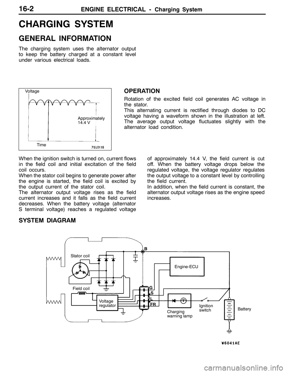
OPERATION
Rotation of the excited field coil generates AC voltage in
the stator.
This alternating current is rectified through diodes to DC
voltage having a waveform shown in the illustration at left.
The average output voltage fluctuates slightly with the
alternator load condition.
When the ignition switch is turned on, current flows
in the field coil and initial excitation of the field
coil occurs.
When the stator coil begins to generate power after
the engine is started, the field coil is excited by
the output current of the stator coil.
The alternator output voltage rises as the field
current increases and it falls as the field current
decreases. When the battery voltage (alternator
S terminal voltage) reaches a regulated voltageof approximately 14.4 V, the field current is cut
off. When the battery voltage drops below the
regulated voltage, the voltage regulator regulates
the output voltage to a constant level by controlling
the field current.
In addition, when the field current is constant, the
alternator output voltage rises as the engine speed
increases.
SYSTEM DIAGRAM
Stator coil
Field coil
Voltage
regulatorEngine-ECU
Charging
warning lampIgnition
switchBattery B
G
L
FRS
Voltage
Time
Approximately
14.4 V
Page 735 of 1449
ENGINE ELECTRICAL -Charging System16-3
ALTERNATOR SPECIFICATIONS
ItemsSpecifications
TypeBattery voltage sensing
Rated output V/A12/90
Voltage regulatorElectronic built-in type
SERVICE SPECIFICATIONS
ItemsStandard valueLimit
Alternator output line voltage drop (at 30 A) V-max. 0.3
Regulated voltage ambient
tempatvoltageregulatorV
-20_C14.2 - 15.4-
temp. atvoltage regulatorV
20_C13.9 - 14.9-
60_C13.4 - 14.6-
80_C13.1 - 14.5-
Output current-70 % of normal output current
Rotor coil resistanceΩApprox. 3 - 5-
Protrusion length of brush mm-2
SPECIAL TOOL
ToolNumberNameUse
MB991519Alternator test
harnessChecking the alternator (S terminal voltage)
Page 742 of 1449

ENGINE ELECTRICAL -Charging System16-10
EXAMPLES OF ABNORMAL WAVEFORMS
NOTE
1. The size of the waveform patterns differs largely, depending on the adjustment of the variable knob
on the analyzer.
2. Identification of abnormal waveforms is easier when there is a large output current (regulator is not
operating). (Waveforms can be observed when the headlamps are illuminated.)
3. Check the conditions of the charging warning lamp (illuminated/not illuminated). Also, check the charging
system totally.
Abnormal waveformsProblem
causeAbnormal waveformsProblem
cause
Example 1Open diodeExample 4Short in
stator coil
Example 2Short in diodeExample 5Open
supplementa-
ry diode
Example 3Broken wire
in stator coil
At this time, the charging warning lamp
is illuminated.
ALTERNATOR
REMOVAL AND INSTALLATION
Caution
If the vehicle is equipped with the Brembo disc brake, during maintenance, take care not to contact
the parts or tools to the caliper because the paint of caliper will be scratched.
Pre-removal and Post-installation Operation
DUnder Cover Removal and Installation (Refer to GROUP 51 - Front Bumper.)
DDrive Belt Tension Check (Refer to GROUP 11A - On-vehicle Service.)
DStrut Tower Bar Removal and Installation (Refer to GROUP 42.)
DCrossmember Bar Removal and Installation (Refer to GROUP 32 - Engine Roll Stopper, Centermember.)
DFront Exhaust Pipe Assembly Removal and Installation (Refer to GROUP 15.)
Page 743 of 1449
ENGINE ELECTRICAL -Charging System16-11
1
234
5
8.8±1.0 N·m 22±4 N·m
23±3 N·m11±1 N·m
13±1 N·m
8
(Engine oil)
679
10
20±2 N·m 36±6 N·m
1211
44±10 N·m
14±3 N·m
13
1415 18
1617
9.0±1.0 N·m
9.0±1.0 N·m5.0±1.0 N·m
Removal steps
1. Oil level gauge and guide assembly
2. O-ring
3. Fuel pressure solenoid valve
connector
4. Fuel pressure solenoid valve
assembly
5. Detonation sensor connector
6. Purge control solenoid valve
connector
7. Purge control solenoid valve assembly
8. Injector connector
AA"9. Delivery pipe, injector, and fuel
pressure regulator assembly10. Insulator
11. Insulator
AB"12. Drive belt
13. Alternator connector
DEngine mounting
(Refer to GROUP 32.)
AC"14. Alternator
15. Water pump pulley
16. Alternator brace
17. Oxygen sensor connector
18. Alternator brace stay
Page 746 of 1449

ENGINE ELECTRICAL -Charging System16-14
DISASSEMBLY SERVICE POINTS
AA"FRONT BRACKET ASSEMBLY REMOVAL
Insert a flat tip screwdrivers or the like in the clearance between
the front bracket assembly and stator core, to pry open and
separate the stator and front bracket.
Caution
Do not insert a screwdriver too far, or the stator coil gets
damaged.
AB"ALTERNATOR PULLEY REMOVAL
Face pulley side upward, fix the rotor with a work bench
and remove the pulley.
Caution
Use care not to damage the rotor.
AC"STATOR/REGULATOR ASSEMBLY REMOVAL
1. Unsolder the stator with a soldering iron (180 to 250
W). Complete this work within four seconds not to transfer
heat to the diode.
2. When removing rectifier from the regulator assembly,
remove the soldered sections to rectifier.
Caution
(1) Use care to make sure that the heat of the soldering
iron is not transmitted to the diodes for a long period.
(2) Use care that no undue force is exerted to the
lead wires of the diodes.
REASSEMBLY SERVICE POINTS
"AAREGULATOR ASSEMBLY INSTALLATION
After installing the regulator assembly, insert a wire into the
hole provided on the rear bracket while pressing in the brush
to fix the brush.
NOTE
The brush is fixed when a wire is inserted, making rotor
installation easier.
SolderedRectifier
assembly
Soldered
Wire
Rear bracket
BrushWire
Page 747 of 1449
ENGINE ELECTRICAL -Charging System16-15
"BAROTOR INSTALLATION
After installing the rotor, remove the wire used to fix the brush.
INSPECTION
ROTOR CHECK
1. Check the continuity between the rotor coil slip rings,
and replace the rotor if the resistance value is not at
the standard value.
Standard value: 3 - 5Ω
2. Check the continuity between the slip ring and core, and
if there is continuity, replace the rotor.
STATOR CHECK
1. Check the continuity between the coil leads, and if there
is continuity, replace the stator.
2. Check the continuity between the coil and core, and if
there is continuity, replace the stator.
Wire