2007 MITSUBISHI LANCER EVOLUTION engine oil
[x] Cancel search: engine oilPage 858 of 1449

MANUAL TRANSMISSION - Transfer Assembly22A-50
11 12
9
1013
14
15 16
13
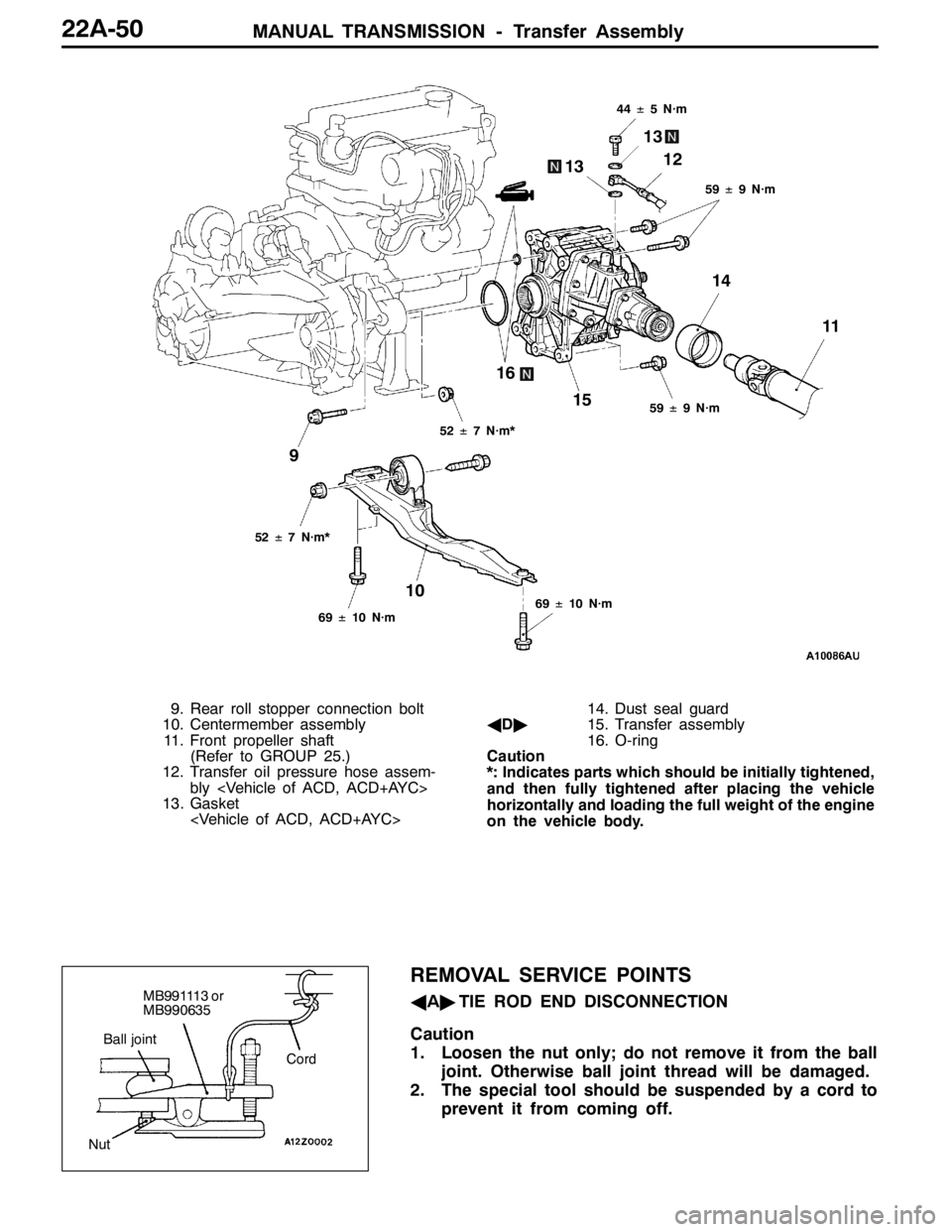
59±9 N·m
59±9 N·m
44±5 N·m
69±10 N·m
52±7 N·m*
52±7 N·m*
69±10 N·m
9. Rear roll stopper connection bolt
10. Centermember assembly
11. Front propeller shaft
(Refer to GROUP 25.)
12. Transfer oil pressure hose assem-
bly
13. Gasket
AD"15. Transfer assembly
16. O-ring
Caution
*: Indicates parts which should be initially tightened,
and then fully tightened after placing the vehicle
horizontally and loading the full weight of the engine
on the vehicle body.
REMOVAL SERVICE POINTS
AA"TIE ROD END DISCONNECTION
Caution
1. Loosen the nut only; do not remove it from the ball
joint. Otherwise ball joint thread will be damaged.
2. The special tool should be suspended by a cord to
prevent it from coming off.MB991113 or
MB990635
Cord Ball joint
Nut
Page 860 of 1449

MANUAL TRANSMISSION - Transmission Assembly22A-52
TRANSMISSION ASSEMBLY
REMOVAL AND INSTALLATION
Pre-removal and Post-installation Operation
DTransfer Assembly Removal and Installation (Refer to P.22A-49.)
DStarter Motor Removal and Installation (Refer to GROUP 16.)
DAir Cleaner Bracket Removal and Installation (Refer to GROUP 15 - Air Cleaner.)
DRear Roll Rod Assembly and Rear Roll Rod Bracket
Removal and Installation (Refer to GROUP 32 - Engine Roll Stopper.)
1
2
3 45
5 6
7
18±3 N·m18±3 N·m
18±3 N·m
70±10 N·m
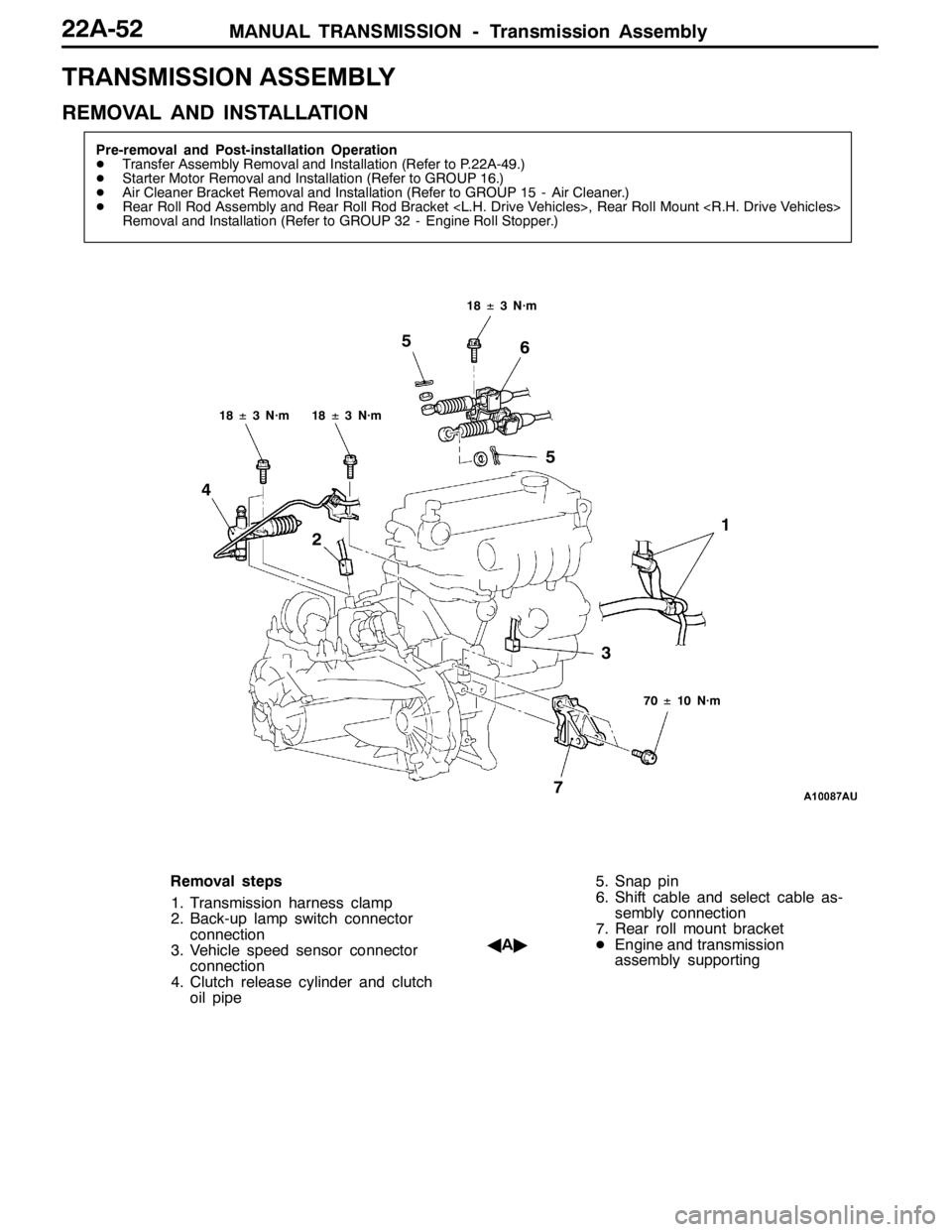
Removal steps
1. Transmission harness clamp
2. Back-up lamp switch connector
connection
3. Vehicle speed sensor connector
connection
4. Clutch release cylinder and clutch
oil pipe5. Snap pin
6. Shift cable and select cable as-
sembly connection
7. Rear roll mount bracket
AA"DEngine and transmission
assembly supporting
Page 960 of 1449

REAR AXLE -Troubleshooting
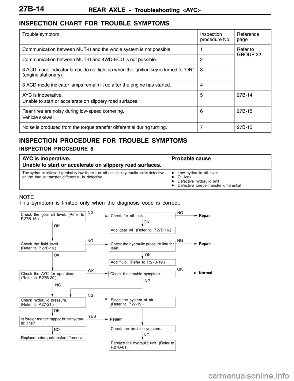
INSPECTION CHART FOR TROUBLE SYMPTOMS
Trouble symptomInspection
procedure No.Reference
page
Communication between MUT-IIand the whole system is not possible.1Refer to
GROUP22
Communication between MUT-IIand 4WD-ECU is not possible.2
GROUP22.
3 ACD mode indicator lamps do not light up when the ignition key is turned to “ON”
(engine stationary).3
3 ACD mode indicator lamps remain lit up after the engine has started.4
AYC is inoperative.
Unable to start or accelerate on slippery road surfaces.527B-14
Rear tires are noisy during low-speed cornering.
Vehicle skews.627B-15
Noise is produced from the torque transfer differential during turning.727B-15
INSPECTION PROCEDURE FOR TROUBLE SYMPTOMS
INSPECTION PROCEDURE 5
AYC is inoperative.
Unable to start or accelerate on slippery road surfaces.
Probable cause
The hydraulic oil level is probably low, there is an oil leak, the hydraulic unit is defective,
or the torque transfer differential is defective.DLow hydraulic oil level
DOil leak
DDefective hydraulic unit
DDefective torque transfer differential
NOTE
This symptom is limited only when the diagnosis code is correct.
NG
Replace the hydraulic unit. (Refer to
P.27B-61.)
NG
Add fluid. (Refer to P.27B-19.)
OKRepair
Check the trouble symptom.NO
Replace the torque transfer differential.
OK
Is foreign matter trapped in the hydrau-
lic line?YES
Repair
OK
Check the fluid level.
(Refer to P.27B-19.)Check the hydraulic pressure line for
leak.
OK
Add gear oil. (Refer to P.27B-16.)
OK
Check hydraulic pressure.
(Refer to P.27-21.)NGBleed the system of air.
(Refer to P.27-19.)
Check the gear oil level. (Refer to
P.27B-16.)NGCheck for oil leak.NG
Repair
Check the AYC for operation.
(Refer to P.27B-20.)Check the trouble symptom. OKOK
NGNormal
NGNG
Page 966 of 1449

REAR AXLE -On-vehicle Service27B-20
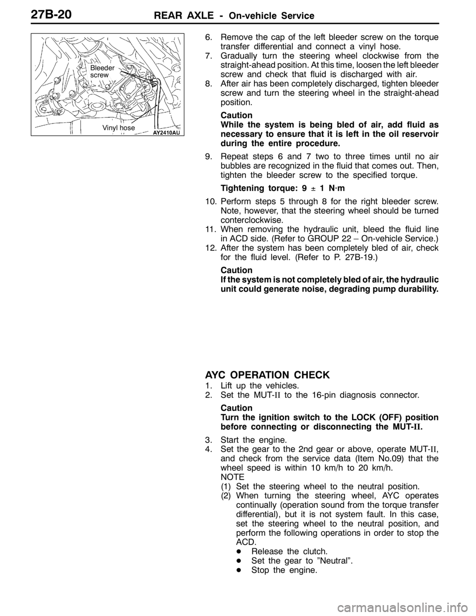
6. Remove the cap of the left bleeder screw on the torque
transfer differential and connect a vinyl hose.
7. Gradually turn the steering wheel clockwise from the
straight-ahead position. At this time, loosen the left bleeder
screw and check that fluid is discharged with air.
8. After air has been completely discharged, tighten bleeder
screw and turn the steering wheel in the straight-ahead
position.
Caution
While the system is being bled of air, add fluid as
necessary to ensure that it is left in the oil reservoir
during the entire procedure.
9. Repeat steps 6 and 7 two to three times until no air
bubbles are recognized in the fluid that comes out. Then,
tighten the bleeder screw to the specified torque.
Tightening torque: 9±1 N·m
10. Perform steps 5 through 8 for the right bleeder screw.
Note, however, that the steering wheel should be turned
conterclockwise.
11. When removing the hydraulic unit, bleed the fluid line
in ACD side. (Refer to GROUP 22 – On-vehicle Service.)
12. After the system has been completely bled of air, check
for the fluid level. (Refer to P. 27B-19.)
Caution
If the system is not completely bled of air, the hydraulic
unit could generate noise, degrading pump durability.
AYC OPERATION CHECK
1. Lift up the vehicles.
2. Set the MUT-IIto the 16-pin diagnosis connector.
Caution
Turn the ignition switch to the LOCK (OFF) position
before connecting or disconnecting the MUT-II.
3. Start the engine.
4. Set the gear to the 2nd gear or above, operate MUT-II,
and check from the service data (Item No.09) that the
wheel speed is within 10 km/h to 20 km/h.
NOTE
(1) Set the steering wheel to the neutral position.
(2) When turning the steering wheel, AYC operates
continually (operation sound from the torque transfer
differential), but it is not system fault. In this case,
set the steering wheel to the neutral position, and
perform the following operations in order to stop the
ACD.
DRelease the clutch.
DSet the gear to ”Neutral”.
DStop the engine.
Bleeder
screw
Vinyl hose
Page 970 of 1449

REAR AXLE -On-vehicle Service27B-24
Torque transfer mechanism part
1. Remove the drive shaft. (Refer to P. 27B-29.)
2. Remove the oil seal from the differential carrier.
3. Using the special tool, drive a new oil seal all the way
into position.
4. Coat the oil seal lips and the drive shaft surface in contact
with the oil seal with the specified grease.
Specified grease: Vaseline
5. Replace the drive shaft circlip with a new one and mount
the drive shaft to the differential carrier. (Refer to P.
27B-29.)
6. Check for correct wheel alignment. (Refer to GROUP
34 – On-vehicle Service.)
ACTION WHEN BATTERY RUNS OUT
When the engine is started using a booster cable where the
battery has completely run down and you attempt to start
the vehicle without waiting for the battery to recover a certain
charge, the engine can misfire and you just cannot start to
move it. In such cases, charge the battery sufficiently; or,
remove the AYC battery cable from the battery fuse assembly
to make AYC inactive before attempting to start the vehicles.
When the battery cable is removed, the ACD mode indicator
lamp lights up. After the battery has been recharged, fit the
battery cable back again and start the engine to ensure that
the ACD mode indicator lamp is off.
MD998829
MD998813 MD998812
Battery fuse assembly
Battery cable
for AYC
Page 1063 of 1449

BASIC BRAKE SYSTEM -Disc Brake35A-21
INSTALLATION SERVICE POINT
"AADISC BRAKE ASSEMBLY INSTALLATION
1. In order to measure the brake drag force after pad
installation, measure the rotary-sliding resistance of the
hub by the following procedure with the pads removed.
(1) Withdraw the drive shaft. (Refer to GROUP 26, 27.)
(2) Attach the special tool to the front hub assembly as
shown in the illustration, and tighten it to the specified
torque.
Tightening torque:
245±29 N·m
(3) Use a spring balance to measure the rotary-sliding
resistance of the hub in the forward direction.
2. Install the caliper support to the knuckle, and then
assemble the pad and the clip to the caliper support.
Caution
Do not contaminate the friction surfaces of the pads
and brake discs by any oil or grease.
3. Clean the piston and insert it into the cylinder with the
special tool.
4. Be careful that the piston boot does not become caught,
when lowering the caliper assembly and install the guide
pin to the caliper.
5. Start the engine, and then depress the brake pedal two
or three times strongly. Then stop the engine.
6. Turn the brake disc forward 10 times.
7. Use a spring balance to measure the rotary-sliding
resistance of the hub in the forward direction.
8. Calculate the drag force of the disc brake [difference
between the values measured at steps 1 and 7].
Standard value:
51 N or less
9. If that drag force exceeds the standard value, disassemble
the piston assembly. Then check the piston for
contamination or rust, and confirm if the piston or the
piston seal is deteriorated, and if the slide pins slide
smoothly.
1. Find the drag force of the disc brake. (Refer to P.35A-13.)
Standard value: 69 N or less
2. If that drag force exceeds the standard value, disassemble
the piston assembly. Then check the piston for
contamination or rust, and confirm if the piston or the
piston seal is deteriorated.MB990998
Bolt
MB990998Bolt
MB990520
Page 1116 of 1449

STEERING -General Information37A-2
GENERAL INFORMATION
The system has been equipped with the MOMO
leather 3-spoke-type steering wheel with built-in
SRS airbag.
The steering column is equipped with tilt steering
mechanism.
The power steering is an integral rack and piniontype that combines the steering gear and linkage
into one light-weight and compact assembly.
The steering system uses a vane oil pump with
a fluid flow control system, so that steering effort
varies with engine speed.
ItemLancer EVOLUTION-
Steering wheelTypeMOMO 3-spoke typeg
Outside diameter mm380
365
Maximum number of turns2.1
Steering columnColumn mechanismTilt steering
Power steering typeIntegral type
Oil pumpTypeVariable capacity type (vane pump)pp
Basic discharge amount cm3/rev.9.6
Relief pressure MPa8.3 - 9.0
Reservoir typeSeparate type
Pressure switchEquipped
Steering gear and linkageTypeRack and pinionggg
Stroke ratio (Rack stroke/Steering wheel
Maximum turning radius)68.61
Rack stroke mm146
Steering angleInner wheel32°gg
Outer wheel (for reference)27°
Power steering fluidSpecified lubricantsAutomatic transmission fluid DEXRON IIg
Quantity LApproximately 1.0
Page 1118 of 1449

STEERING -Service Specifications/Lubricants/Sealant/Special Tools37A-4
SERVICE SPECIFICATIONS
ItemsStandard valueLimit
Steering wheel free play mmwhen engine running-30 or less
with engine stopped0-10-
Steering angleInner wheel31_45’±1_30’-
Outer wheel
Ball joint turning torque N·m1.0 - 3.0-
Stationary steering effort NSteering effort32 or less-
Fluctuation allowance6.0 or less-
Oil pump relief pressure MPa8.4 - 9.0-
Pressure under no-load conditions MPa0.2 - 0.8-
Steering gear retention hydraulic pressure MPa8.4 - 9.0-
Oil pressure switch operating
pressureMPa
OFF→ON1.8 - 2.4-
pressure MPaON→OFF1.0 - 2.4-
Total pinion torque N·mTotal rotation torque0.8 - 1.8-
Torque variation0.49 or less-
Tie rod joint swing resistance N (Tie rod joint swing torque N·m)8 - 27 (1.5 - 4.9)-
Opening dimension of special tool (MB991561) mm2.9-
Band crimped width mm2.4 - 2.8-
LUBRICANTS
ItemsSpecified lubricantQuantity
Power steering fluidAutomatic transmission fluid DEXRONIIApprox. 1.0 L
Tie rod bellowsSilicone greaseAs required
Pinion and valve assemblyRepair kit greaseAs required
Rack assembly
SEALANT
ItemsSpecified sealantRemarks
Toe boad (steering shaft cover
mounting bolt hole)3M ATD Part No. 8513 or equivalentDrying sealant
Rack support cover end plug3M ATD Part No. 8661, 8663 or equivalentSemi-drying sealant
SPECIAL TOOLS
ToolNumberNameUse
MB990635,
MB991113 or
MB991406Steering linkage
pullerDisconnection of tie rod end