Page 700 of 1449
ENGINE COOLING -Thermostat14-12
INSTALLATION SERVICE POINTS
"AATHERMOSTAT INSTALLATION
Install the thermostat being careful not to fold over or scratch
the rubber ring.
Caution
Make absolutely sure that no oil is adhering to the rubber
ring of the thermostat. In addition, be careful not to fold
over or scratch the rubber ring when inserting. If the
rubber ring is damage, replace the thermostat.
"BARADIATOR UPPER HOSE CONNECTION
1. Insert each hose as far as the projection of the water
outlet fitting.
2. Align the mating marks on the radiator hose and hose
clamp, and then connect the radiator hose.
INSPECTION
THERMOSTAT CHECK
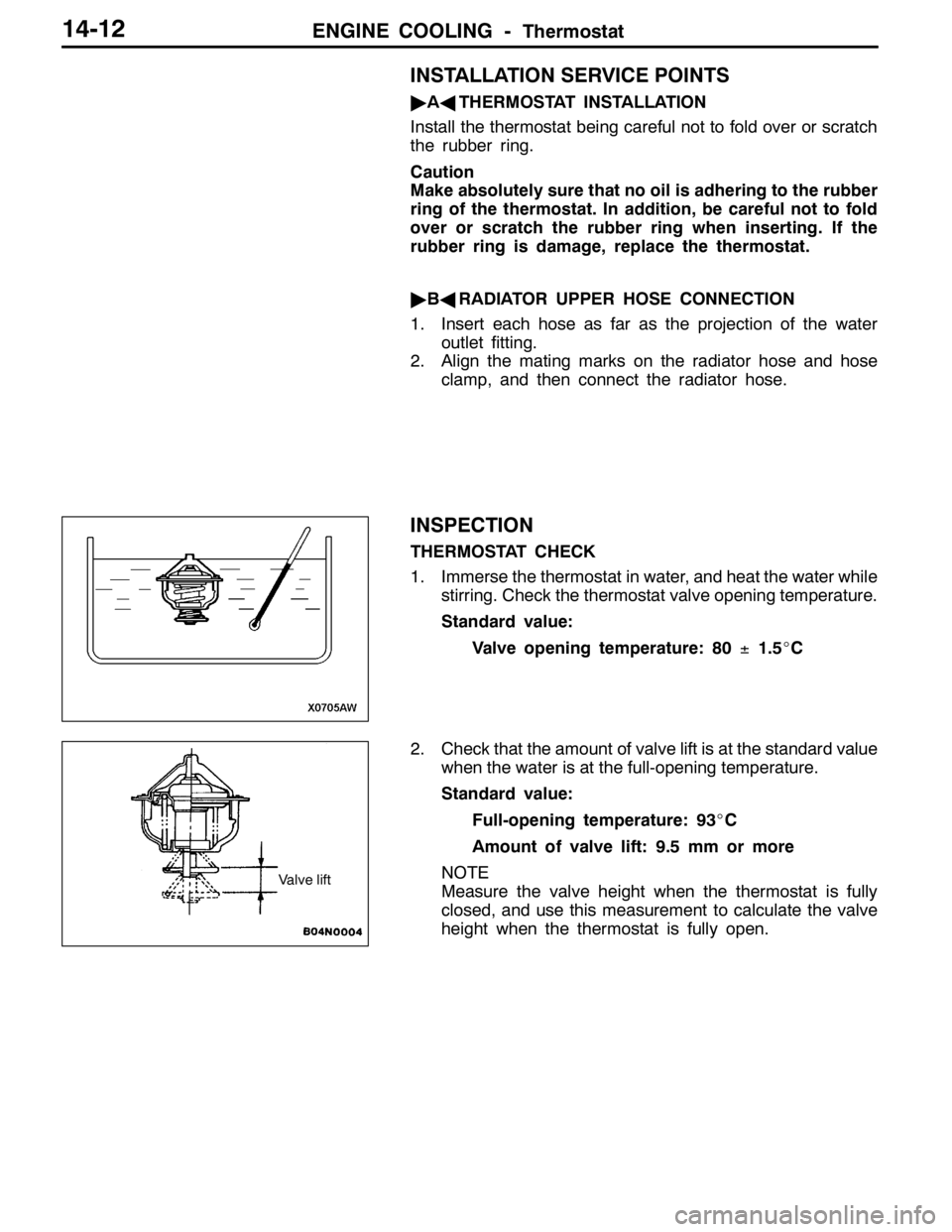
1. Immerse the thermostat in water, and heat the water while
stirring. Check the thermostat valve opening temperature.
Standard value:
Valve opening temperature: 80±1.5_C
2. Check that the amount of valve lift is at the standard value
when the water is at the full-opening temperature.
Standard value:
Full-opening temperature: 93_C
Amount of valve lift: 9.5 mm or more
NOTE
Measure the valve height when the thermostat is fully
closed, and use this measurement to calculate the valve
height when the thermostat is fully open.
Valve lift
Page 701 of 1449
ENGINE COOLING -Water Pump14-13
WATER PUMP
Caution
If the vehicle is equipped with the Brembo disc brake, during maintenance, take care not to contact
the parts or tools to the caliper because the paint of caliper will be scratched.
REMOVAL AND INSTALLATION
Pre-remobal and Post-installation Operation
DEngine Coolant Draining and Supplying (Refer to P.14-6.)
DTiming Belt Removal and installation (Refer to GROUP 11A.)
1
Bolt specifications
28×22
2
23±3 N·m
14±1 N·m
Nominal diameter×Nominal length mm
8×70
8×14
8×22 8×25
3 4
22±4 N·m
Removal steps
1. Alternator brace
2. Water pump
3. Water pump Gasket
"AA4. O-ring
INSTALLATION SERVICE POINT
"AAO-RING INSTALLATION
Fit an O-ring into the O-ring groove located at the end of
the water inlet pipe and apply water to the O-ring or the
inside of the mounting surface of the water pump for insertion.
CAUTION
Do not let the O-ring get contaminated with grease, such
as engine oil.Water pump
O-ring
Water inlet pipe
Page 703 of 1449
ENGINE COOLING -Water Hose and Water Pipe/Radiator14-15
REMOVAL SERVICE POINT
AA"RADIATOR UPPER HOSE/RADIATOR LOWER
HOSE DISCONNECTION
After making mating marks on the hose and the hose clamp,
disconnect the hose.
INSTALLATION SERVICE POINTS
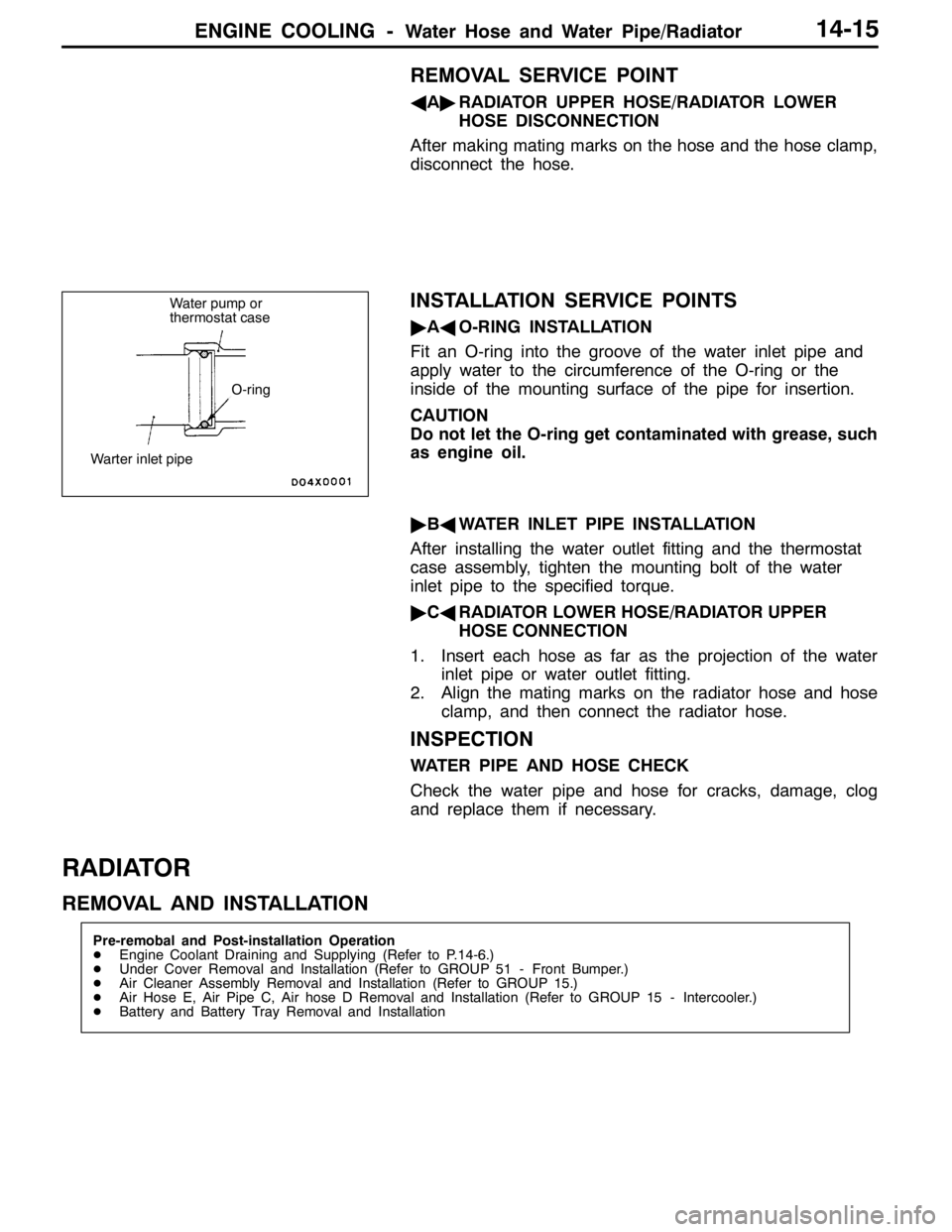
"AAO-RING INSTALLATION
Fit an O-ring into the groove of the water inlet pipe and
apply water to the circumference of the O-ring or the
inside of the mounting surface of the pipe for insertion.
CAUTION
Do not let the O-ring get contaminated with grease, such
as engine oil.
"BAWATER INLET PIPE INSTALLATION
After installing the water outlet fitting and the thermostat
case assembly, tighten the mounting bolt of the water
inlet pipe to the specified torque.
"CARADIATOR LOWER HOSE/RADIATOR UPPER
HOSE CONNECTION
1. Insert each hose as far as the projection of the water
inlet pipe or water outlet fitting.
2. Align the mating marks on the radiator hose and hose
clamp, and then connect the radiator hose.
INSPECTION
WATER PIPE AND HOSE CHECK
Check the water pipe and hose for cracks, damage, clog
and replace them if necessary.
RADIATOR
REMOVAL AND INSTALLATION
Pre-remobal and Post-installation Operation
DEngine Coolant Draining and Supplying (Refer to P.14-6.)
DUnder Cover Removal and Installation (Refer to GROUP 51 - Front Bumper.)
DAir Cleaner Assembly Removal and Installation (Refer to GROUP 15.)
DAir Hose E, Air Pipe C, Air hose D Removal and Installation (Refer to GROUP 15 - Intercooler.)
DBattery and Battery Tray Removal and Installation
Water pump or
thermostat case
O-ring
Warter inlet pipe
Page 709 of 1449
INTAKE AND EXHAUST -Service Specifications/Special Tool/On-vehicle Service15-3
SERVICE SPECIFICATIONS
ItemStandard valueLimit
Turbocharger supercharging pressure (waste gate solenoid
valve not operating) kPa59 - 84-
Initial activation pressure of waste gate actuator (at the stroke
of approximately 1 mm) kPaApproximately 100-
Waste gate solenoid valve coil resistance (at 20_C)Ω29 - 35-
Initial activation pressure of air bypass valve kPaApproximately 53-
Secondary air control solenoid valve coil resistance
(at 20_C)Ω29 - 35-
Manifold distortion of the installation surface mm0.15 or less0.20
SPECIAL TOOL
ToolNumberNameUse
MD998770Oxygen sensor wrenchRemoval and installation of oxygen sensor
ON-VEHICLE SERVICE
TURBOCHARGER SUPERCHARGING
PRESSURE CHECK
Caution
Two persons should be in the vehicle when the test is
conducted; the person in the passenger seat should read
the indications shown by the pressure meter.
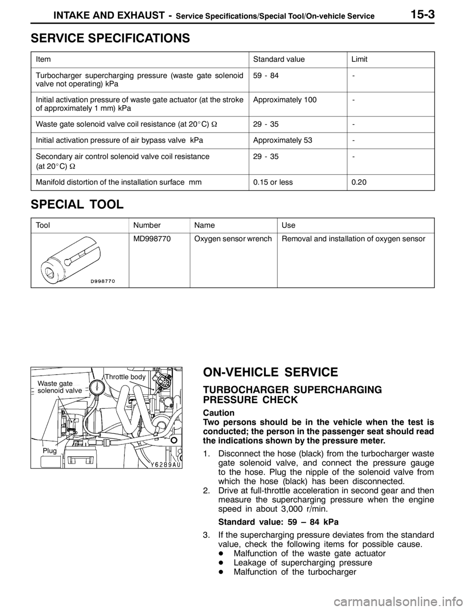
1. Disconnect the hose (black) from the turbocharger waste
gate solenoid valve, and connect the pressure gauge
to the hose. Plug the nipple of the solenoid valve from
which the hose (black) has been disconnected.
2. Drive at full-throttle acceleration in second gear and then
measure the supercharging pressure when the engine
speed in about 3,000 r/min.
Standard value: 59 – 84 kPa
3. If the supercharging pressure deviates from the standard
value, check the following items for possible cause.
DMalfunction of the waste gate actuator
DLeakage of supercharging pressure
DMalfunction of the turbocharger
Throttle bodyWaste gate
solenoid valve
Plug
Page 722 of 1449
INTAKE AND EXHAUST -Intake Manifold15-16
INTAKE MANIFOLD
REMOVAL AND INSTALLATION
Pre-removal and Post-installation Operation
DAir Duct Removal and Installation (Refer to P.15-8.)
DStrut Tower Bar Removal and Installation
(Refer to GROUP 42.)
DUnder Cover Removal and Installation
(Refer to GROUP 51 - Front Bumper.)
DEngine Coolant Draining and Supplying
(Refer to GROUP 14 - On-vehicle Service.)
DThrottle Body Removal and Installation (Refer to
GROUP 13A - Throttle Body.)DCrossmember Bar Removal and Installation (Refer
to GROUP 32 - Engine Roll Stopper, Centermember.)
DFront Exhaust Pipe Removal and Installation (Refer
to GROUP 15 - Exhaust Pipe and Main Muffler.)
DSecondary Air Control Valve Bracket Removal and
Installation (Refer to P.15-14.)
DEngine Oil Draining and Supplying
1
2
3 4
5 6 7
8 10
11
1214
13
15
16 17
18
9
11±1 N·m3.0±0.5 N·m
13±1 N·m
(Engine oil)
(Engine oil) 5.0±1.0 N·m
14 8
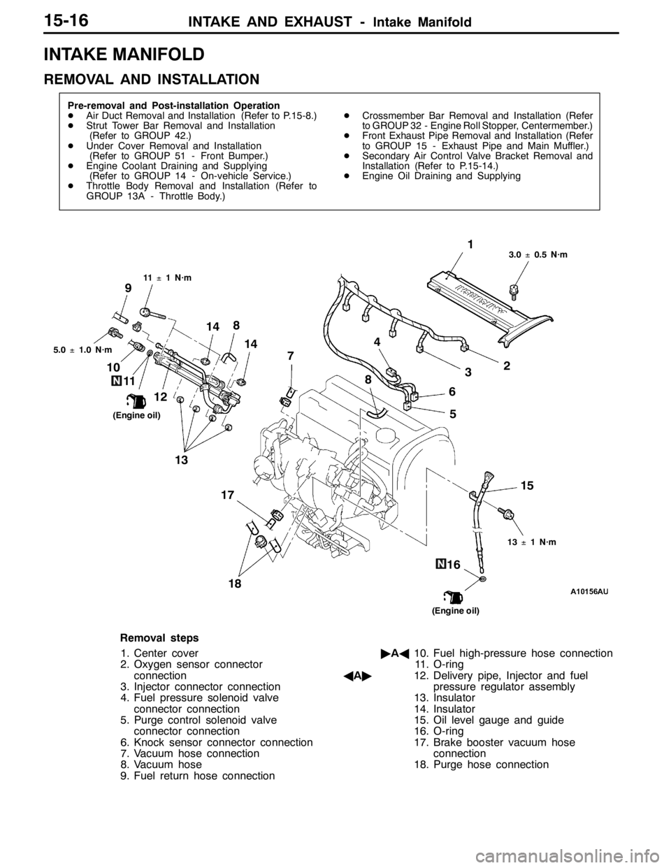
Removal steps
1. Center cover
2. Oxygen sensor connector
connection
3. Injector connector connection
4. Fuel pressure solenoid valve
connector connection
5. Purge control solenoid valve
connector connection
6. Knock sensor connector connection
7. Vacuum hose connection
8. Vacuum hose
9. Fuel return hose connection"AA10. Fuel high-pressure hose connection
11. O-ring
AA"12. Delivery pipe, Injector and fuel
pressure regulator assembly
13. Insulator
14. Insulator
15. Oil level gauge and guide
16. O-ring
17. Brake booster vacuum hose
connection
18. Purge hose connection
Page 724 of 1449
INTAKE AND EXHAUST -Intake Manifold15-18
INSTALLATION SERVICE POINTS
"AAFUEL HIGH-PRESSURE HOSE CONNECTION
1. Apply a drop of new engine oil to the O-ring.
Caution
Be sure not to let engine oil enter the delivery pipe.
2. While turning the injector, high-pressure fuel hose and
fuel pressure regulator to the right and left, install the
delivery pipe, while being careful not to damage the O-ring.
After installing, check that the hose turns smoothly.
3. If it does not turn smoothly, the O-ring may be trapped,
remove the injector, high-pressure fuel hose or fuel
pressure regulator and then re-insert it into the delivery
pipe and check once again.
4. Tighten the high-pressure fuel hose to the specified torque.
Tightening torque: 5.0±1.0 N⋅m
INSPECTION
Check the following points; replace the part if a problem is
found.
INTAKE MANIFOLD CHECK
1. Check for damage or cracking of any part.
2. Check for obstruction of the negative pressure (vacuum)
outlet port, and for obstruction of the water passage or
gas passage.
3. Using a straight edge and thickness gauge, check for
distortion of the cylinder head installation surface.
Standard value: 0.15 mm
Limit: 0.20 mm
Page 725 of 1449
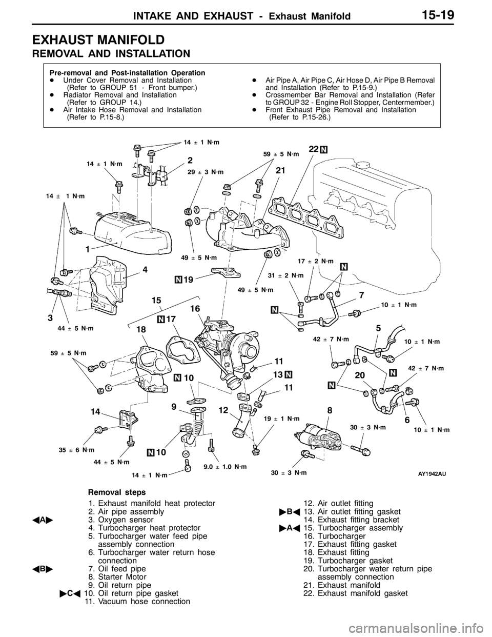
INTAKE AND EXHAUST -Exhaust Manifold15-19
EXHAUST MANIFOLD
REMOVAL AND INSTALLATION
Pre-removal and Post-installation Operation
DUnder Cover Removal and Installation
(Refer to GROUP 51 - Front bumper.)
DRadiator Removal and Installation
(Refer to GROUP 14.)
DAir Intake Hose Removal and Installation
(Refer to P.15-8.)DAir Pipe A, Air Pipe C, Air Hose D, Air Pipe B Removal
and Installation (Refer to P.15-9.)
DCrossmember Bar Removal and Installation (Refer
to GROUP 32 - Engine Roll Stopper, Centermember.)
DFront Exhaust Pipe Removal and Installation
(Refer to P.15-26.)
13 12
3
6 5
8
9
11 192122
14�¶1 N·m
4
7
11
12 15
16
17
18
20
1010
14
14±1 N·m
14±1 N·m
29±3 N·m
59±5 N·m
49±5 N·m
44±5 N·m
59±5 N·m
35±6 N·m
44±5 N·m
14±1 N·m9.0±1.0 N·m30±3 N·m
30±3 N·m10±1 N·m
42±7 N·m
10±1 N·m
10±1 N·m
17±2 N·m
31±2 N·m
49±5 N·m
42±7 N·m
19±1 N·m
Removal steps
1. Exhaust manifold heat protector
2. Air pipe assembly
AA"3. Oxygen sensor
4. Turbocharger heat protector
5. Turbocharger water feed pipe
assembly connection
6. Turbocharger water return hose
connection
AB"7. Oil feed pipe
8. Starter Motor
9. Oil return pipe
"CA10. Oil return pipe gasket
11. Vacuum hose connection12. Air outlet fitting
"BA13. Air outlet fitting gasket
14. Exhaust fitting bracket
"AA15. Turbocharger assembly
16. Turbocharger
17. Exhaust fitting gasket
18. Exhaust fitting
19. Turbocharger gasket
20. Turbocharger water return pipe
assembly connection
21. Exhaust manifold
22. Exhaust manifold gasket
Page 726 of 1449
INTAKE AND EXHAUST -Exhaust ManifoldINTAKE AND EXHAUST -Exhaust Manifold15-20
REMOVAL SERVICE POINT
AA"OXYGEN SENSOR REMOVAL
Use special tool to remove the oxygen sensor.
AB"OIL FEED PIPE REMOVAL
Take care not to let foreign objects get into the oil passage
hole of the turbocharger after the oil feed pipe is removed.
INSTALLATION SERVICE POINT
"AATURBOCHARGER INSTALLATION
1. Clean the oil feed pipe, oil return pipe, water pipe fitting,
the inside of eye bolt, and individual pipe for clogs.
2. Clean or blow the air if carbon particles are stuck to the
oil passage of the turbocharger.
Caution
Take care not to let foreign objects get into the
turbocharger.
3. Refill new engine oil at the oil feed pipe fitting hole of
the turbocharger.
"BAAIR OUTLET FITTING GASKET INSTALLATION
Install the gasket so that its protrusion can face towards the
direction as shown in the illustration.
MD998770
Oxygen sensor
View A
View A
TurbochargerProtrusion