Page 601 of 1449

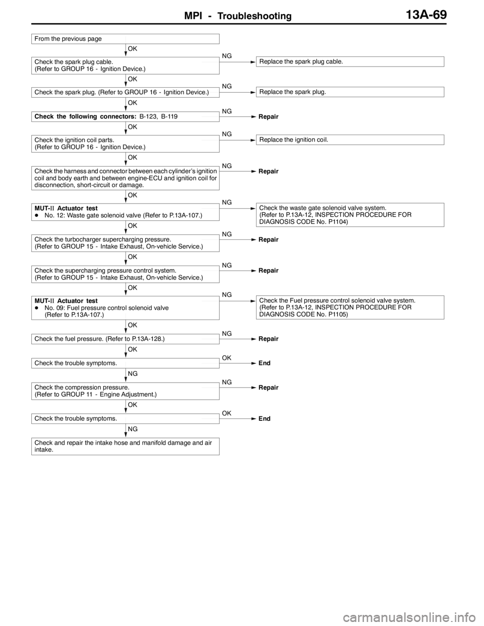
MPI -Troubleshooting13A-69
NG
Check and repair the intake hose and manifold damage and air
intake.
OK
Check the trouble symptoms.OK
End
NG
Check the compression pressure.
(Refer to GROUP 11 - Engine Adjustment.)NG
Repair
OK
Check the trouble symptoms.OK
End
OK
Check the fuel pressure. (Refer to P.13A-128.)NG
Repair
OK
MUT-IIActuator test
DNo. 09: Fuel pressure control solenoid valve
(Refer to P.13A-107.)NGCheck the Fuel pressure control solenoid valve system.
(Refer to P.13A-12, INSPECTION PROCEDURE FOR
DIAGNOSIS CODE No. P1105)
OK
Check the supercharging pressure control system.
(Refer to GROUP 15 - Intake Exhaust, On-vehicle Service.)NG
Repair
OK
Check the turbocharger supercharging pressure.
(Refer to GROUP 15 - Intake Exhaust, On-vehicle Service.)NG
Repair
OK
MUT-IIActuator test
DNo. 12: Waste gate solenoid valve (Refer to P.13A-107.)NGCheck the waste gate solenoid valve system.
(Refer to P.13A-12, INSPECTION PROCEDURE FOR
DIAGNOSIS CODE No. P1104)
OK
Check the harness and connector between each cylinder’s ignition
coil and body earth and between engine-ECU and ignition coil for
disconnection, short-circuit or damage.NG
Repair
OK
Check the ignition coil parts.
(Refer to GROUP 16 - Ignition Device.)NGReplace the ignition coil.
OK
Check the following connectors:B-123, B-119NG
Repair
OK
Check the spark plug. (Refer to GROUP 16 - Ignition Device.)NGReplace the spark plug.
OK
Check the spark plug cable.
(Refer to GROUP 16 - Ignition Device.)NGReplace the spark plug cable.
From the previous page
Page 602 of 1449
MPI -Troubleshooting13A-70
Inspection Procedure 12
Shock during acceleration
Probable cause
The occurrence of ignition leaks, etc., due to the rise in voltage required for the spark
plugs during acceleration is a probable cause.DIgnition system malfunction
OK
Check and repair the harness and connector between each
cylinder’s ignition coil and body earth and between the engine-
ECU and ignition coil for disconnection, short-circuit and damage.
OK
Check the ignition coil parts.
(Refer to GROUP 16 - Ignition Device.)NGReplace the ignition coil.
OK
Check the following connectors:B-114, B-119NG
Repair
OK
Check the spark plug.
(Refer to GROUP 16 - Ignition Device.)NGReplace the spark plug.
NO
Check the spark plug cable.
(Refer to GROUP 16 - Ignition Device.)NGReplace the spark plug cable.
MUT-IISelf-Diag code
DIs a diagnosis code output?YESINSPECTION CHART FOR DIAGNOSIS CODE
(Refer to P.13A-12.)
Page 604 of 1449
MPI -Troubleshooting13A-72
Inspection Procedure 14
Knocking
Probable cause
Causes shown on right are suspected.DDetonation sensor malfunction
DKnocking control system malfunction
DSpark plug malfunction
DIgnition system malfunction
DEngine-ECU malfunction
OK
Check the Code No. P0325: Detonation sensor system.
(Refer to P.13A-34.)
OK
Check the harness and connector between each cylinder’s ignition
coil and body earth and between engine-ECU and ignition coil for
disconnection, short-circuit or damage.NG
Repair
OK
Check the ignition coil parts.
(Refer to GROUP 16 - Ignition Device.)NGReplace the ignition coil.
OK
Check the following connectors:B-114, B-119NG
Repair
OK
Check the spark plug. (Refer to GROUP 16 - Ignition Device.)NGReplace the spark plug.
NO
Check the spark plug cable.
(Refer to GROUP 16 - Ignition Device.)NGReplace the spark plug cable.
MUT-IISelf-Diag code
DIs a diagnosis code output?YESINSPECTION CHART FOR DIAGNOSIS CODE
(Refer to P.13A-12.)
Page 608 of 1449

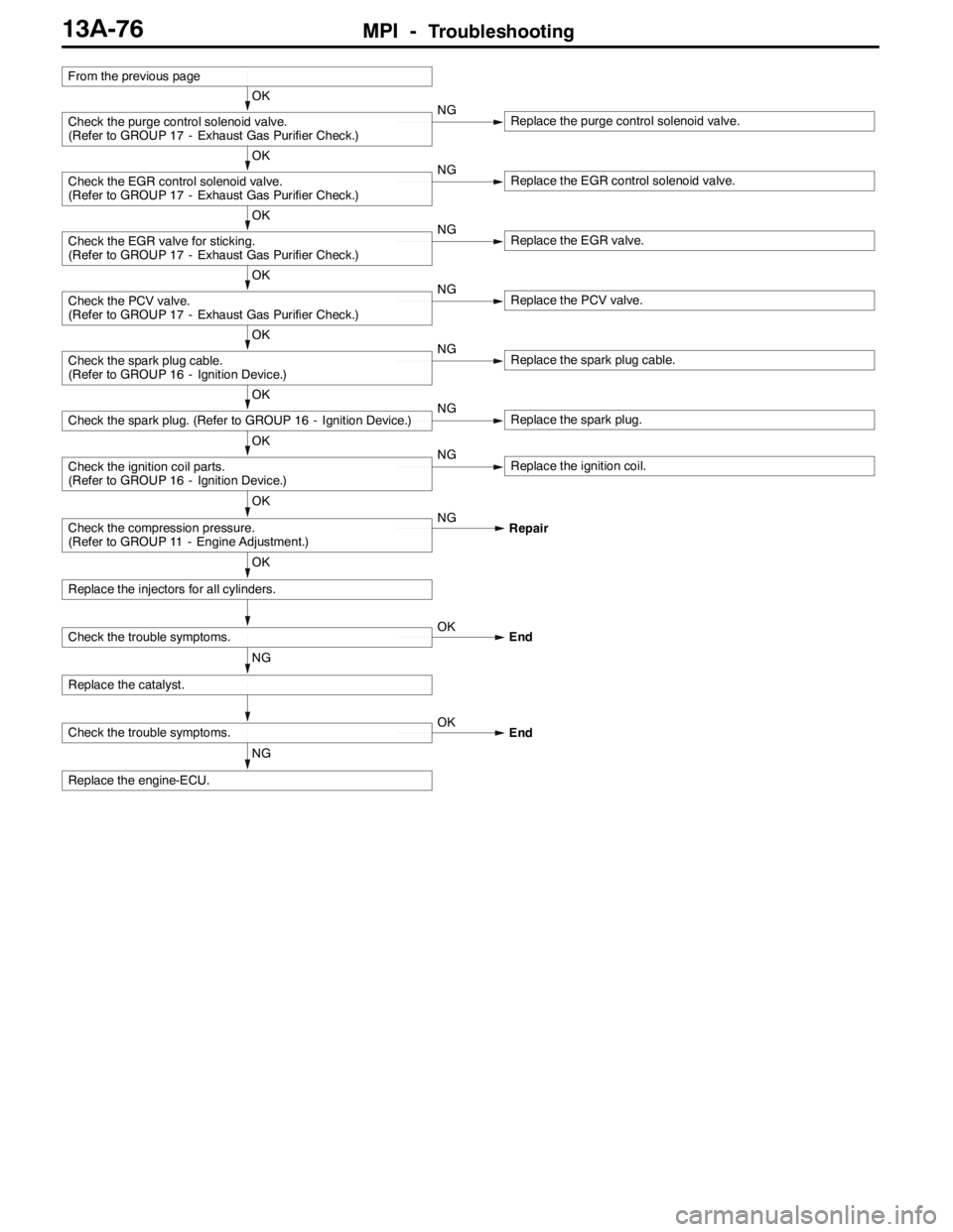
MPI -Troubleshooting13A-76
NG
Replace the engine-ECU.
Check the trouble symptoms.OK
End
NG
Replace the catalyst.
Check the trouble symptoms.OK
End
OK
Replace the injectors for all cylinders.
OK
Check the compression pressure.
(Refer to GROUP 11 - Engine Adjustment.)NG
Repair
OK
Check the ignition coil parts.
(Refer to GROUP 16 - Ignition Device.)NGReplace the ignition coil.
OK
Check the spark plug. (Refer to GROUP 16 - Ignition Device.)NGReplace the spark plug.
OK
Check the spark plug cable.
(Refer to GROUP 16 - Ignition Device.)NGReplace the spark plug cable.
OK
Check the PCV valve.
(Refer to GROUP 17 - Exhaust Gas Purifier Check.)NGReplace the PCV valve.
OK
Check the EGR valve for sticking.
(Refer to GROUP 17 - Exhaust Gas Purifier Check.)NGReplace the EGR valve.
OK
Check the EGR control solenoid valve.
(Refer to GROUP 17 - Exhaust Gas Purifier Check.)NGReplace the EGR control solenoid valve.
OK
Check the purge control solenoid valve.
(Refer to GROUP 17 - Exhaust Gas Purifier Check.)NGReplace the purge control solenoid valve.
From the previous page
Page 632 of 1449

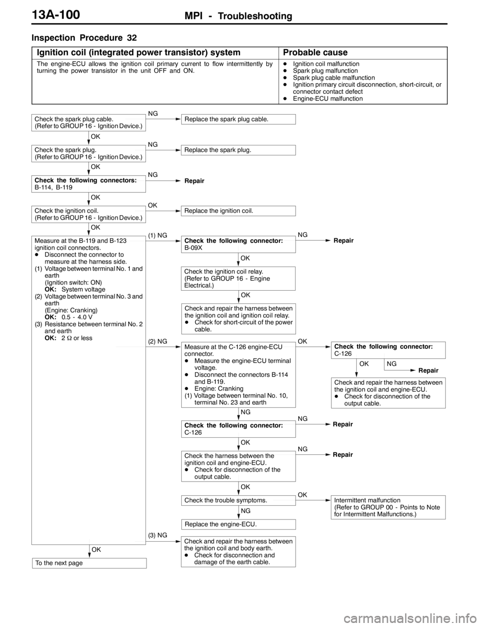
MPI -Troubleshooting13A-100
Inspection Procedure 32
Ignition coil (integrated power transistor) system
Probable cause
The engine-ECU allows the ignition coil primary current to flow intermittently by
turning the power transistor in the unit OFF and ON.DIgnition coil malfunction
DSpark plug malfunction
DSpark plug cable malfunction
DIgnition primary circuit disconnection, short-circuit, or
connector contact defect
DEngine-ECU malfunction
OK
Check and repair the harness between
the ignition coil and engine-ECU.
DCheck for disconnection of the
output cable.
OK
To the next page
(3) NGCheck and repair the harness between
the ignition coil and body earth.
DCheck for disconnection and
damage of the earth cable.
NG
Replace the engine-ECU.
OK
Check the trouble symptoms.OKIntermittent malfunction
(Refer to GROUP 00 - Points to Note
for Intermittent Malfunctions.) NG
OK
Check the harness between the
ignition coil and engine-ECU.
DCheck for disconnection of the
output cable.Repair NG
NG
Check the following connector:
C-126Repair
(2) NGMeasure at the C-126 engine-ECU
connector.
DMeasure the engine-ECU terminal
voltage.
DDisconnect the connectors B-114
and B-119.
DEngine: Cranking
(1) Voltage between terminal No. 10,
terminal No. 23 and earthOKCheck the following connector:
C-126
OK
Check and repair the harness between
the ignition coil and ignition coil relay.
DCheck for short-circuit of the power
cable.
OK
Check the ignition coil relay.
(Refer to GROUP 16 - Engine
Electrical.)
OK
Measure at the B-119 and B-123
ignition coil connectors.
DDisconnect the connector to
measure at the harness side.
(1) Voltage between terminal No. 1 and
earth
(Ignition switch: ON)
OK:System voltage
(2) Voltage between terminal No. 3 and
earth
(Engine: Cranking)
OK:0.5 - 4.0 V
(3) Resistance between terminal No. 2
and earth
OK:2Ωor less(1) NGCheck the following connector:
B-09XNG
Repair
OK
Check the ignition coil.
(Refer to GROUP 16 - Ignition Device.)OKReplace the ignition coil.
OK
Check the following connectors:
B-114, B-119NG
Repair
OK
Check the spark plug.
(Refer to GROUP 16 - Ignition Device.)NGReplace the spark plug.
Check the spark plug cable.
(Refer to GROUP 16 - Ignition Device.)NGReplace the spark plug cable.
NG
Repair
Page 633 of 1449
MPI -Troubleshooting13A-101
NG
Replace the engine-ECU.
Check the trouble symptoms.OKIntermittent malfunction
(Refer to GROUP 00 - Points to Note
for Intermittent Malfunctions.)
OK
Check the harness between the
ignition coil and engine-ECU.
DCheck for damage of the output
cable.NG
Repair
OK
Check the harness between the
ignition coil and ignition coil relay.
DCheck for damage of the power
cable.NG
Repair
From the previous page
Page 641 of 1449

MPI -TroubleshootingMPI -Troubleshooting13A-109
Engine-ECU Connector Terminal Arrangement
Terminal No.Check itemCheck condition (Engine condition)Normal condition
1No. 1 injectorWhile engine is idling after having warmed up,
suddenlydepresstheacceleratorpedal
From 11 - 14 V, momentarily
dropsslightly
14No. 2 injector
suddenlydepressthe accelerator pedal.drops slightly
2No. 3 injector
15No. 4 injector
3Fuel pressure control
solenoidvalve
Ignition switch: “ON”System voltage
solenoidvalve
Engine: Cranking→Idle operation
(within approximately 2 minutes or less)1 V or less→System voltage
4Stepper motor coil
Engine: Soon after the warmed up engine is
startedSystem voltage↔0-6V
(Changes repeatedly)
17Stepper motor coil
5Stepper motor coil
18Stepper motor coil
6EGR control solenoid
valve
Ignition switch: “ON”System Voltage
valve
While engine is idling, suddenly depress the
accelerator pedal.From system voltage,
momentarily drops
8A/C relayDEngine: Idle operation
DA/Cswitch:OFF→ON(A/Ccompressor
System voltage or momen-
tarily6Vormore→1VorDA/Cswitch:OFF→ON(A/Ccompressor
runs)tarily6Vor more→1Vor
less
9Purge control sole-
noidvalve
Ignition switch: “ON”System voltage
noidvalve
Engine: Idle operation1 V or less
10Ignition coil - No.1,
No.4Engine speed: 3,000 r/min0.3 - 3.0 V
23Ignition coil - No.2,
No.3
11Waste gate solenoid
valve
Ignition switch: “ON”System voltage
valve
Engine: After warm-up, idle operation
(When using premium gasoline)1 V or less
Page 647 of 1449

MPI -Troubleshooting13A-115
Terminal No. Normal condition (Check condition)Inspection item
3-12Fuel pressure control solenoid valve28 - 36Ω(at 20_C)
4-12Stepper motor coil (A1)28 - 33Ω(at 20_C)
17 - 12Stepper motor coil (A2)
5-12Stepper motor coil (B1)
18 - 12Stepper motor coil (B2)
6-12EGR control solenoid valve36 - 44Ω(at 20_C)
9-12Purge control solenoid valve22 - 26Ω(at 20_C)
11 - 1 2Waste gate solenoid valve62 - 74Ω(at 20_C)
13 - Body earthENGINE-ECU earthContinuity (0Ω)
26 - Body earthENGINE-ECU earth
53 - 12Secondary air control solenoid valve28 - 36Ω(at 20_C)
54 - 12Oxygen sensor heater (Rear)11 - 1 8Ω(at 20_C)
60 - 12Oxygen sensor heater (Front)4.5 - 8.0Ω(at 20_C)
72 - 92Intake air temperature sensor13 - 17 kΩ(When intake air temperature is - 20_C)
5.7 - 6.7 kΩ(When intake air temperature is 0_C)
2.3 - 3.0 kΩ(When intake air temperature is 20_C)
1.0 - 1.5 kΩ(When intake air temperature is 40_C)
0.56 - 0.76 kΩ(When intake air temperature is 60_C)
0.30 - 0.42 kΩ(When intake air temperature is 80_C)
83 - 92Engine coolant temperature sensor14 - 17 kΩ(When coolant temperature is - 20_C)
5.1 - 6.5 kΩ(When coolant temperature is 0_C)
2.1 - 2.7 kΩ(When coolant temperature is 20_C)
0.9 - 1.3 kΩ(When coolant temperature is 40_C)
0.48 - 0.68 kΩ(When coolant temperature is 60_C)
0.26 - 0.36 kΩ(When coolant temperature is 80_C)