Page 1034 of 6020
ENGINE ELECTRICAL 6D – 33
PRE-HEATING SYSTEM
INSPECTION AND REPAIR
Make the necessary adjustments, repairs, and part replacement if excessive wear of damage is discovered during
inspection.
VISUAL CHECK
Check the main fuses and glow indicator for damage.
Replace the part(s) if required.
GLOW RELAY
The glow relay is located in the relay box the engine
compartment.
825R300046
Use an ohmmeter to measure the resistance between
terminals No.2 and No.3.
If the measured value is outside the specified range, the
glow relay must be replaced.
Glow Relay Resistance Ohms
94 − 114
GLOW PLUG
LNW21KSH001401
Use a circuit tester to test the glow plugs for continuity.
Glow Plug Resistance (Reference) Ohms
Approximately 0.9
EGR SYSTEM 4JA1T (L)
Refer to 6F-9. (EGR system diagram)
BACK TO CHAPTER INDEX
TO MODEL INDEX
ISUZU KB P190 2007
Page 1037 of 6020

Engine Control System (4JH1) 6E-3
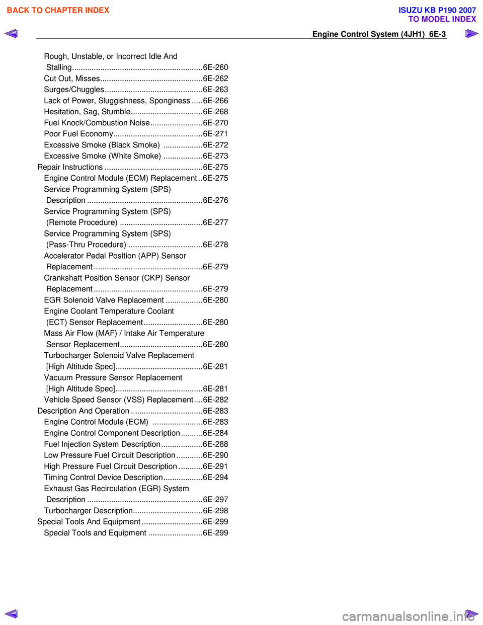
Rough, Unstable, or In co rr ect Idle And
Stallin g........................................................... .6E -260
Cut Out, Mi sses.............................................. .6E -262
Su rge s/Chuggle s............................................ .6E -263
La ck of Po wer, Sluggi shne ss, Spongine ss .... .6E -266
He sitation, Sag, Stu mble................................ .6E -268
Fuel Kno ck /Co mbu stion Noi se ....................... .6E -270
Poor F uel E cono my........................................ .6E -271
E xc ess ive S moke (B la ck S m oke) ................. .6E -272
E xc ess ive S moke (W hite S moke) ................. .6E -273
Repair In str u ctions ............................................ .6E -275
Engine Control Module (ECM) Replacement ..6E-275
Service Programming System (SPS)
Description .....................................................6E-276
Service Programming System (SPS)
(Remote Procedure) ......................................6E-277
Service Programming System (SPS)
(Pass-Thru Procedure) ..................................6E-278
Accelerator Pedal Position (APP) Sensor
Replacement ..................................................6E-279
Crankshaft Position Sensor (CKP) Sensor
Replacement ..................................................6E-279
EGR Solenoid Valve Replacement .................6E-280
Engine Coolant Temperature Coolant
(ECT) Sensor Replacement ...........................6E-280
Mass Air Flow (MAF) / Intake Air Temperature
Sensor Replacement......................................6E-280
Turbocharger Solenoid Valve Replacement
[High Altitude Spec] ........................................6E-281
Vacuum Pressure Sensor Replacement
[High Altitude Spec] ........................................6E-281
Vehicle Speed Sensor (VSS) Replacement ....6E-282
Description And Operation .................................6E-283 Engine Control Module (ECM) .......................6E-283
Engine Control Component Description ..........6E-284
Fuel Injection System Description ...................6E-288
Low Pressure Fuel Circuit Description ............6E-290
High Pressure Fuel Circuit Description ...........6E-291
Timing Control Device Description ..................6E-294
Exhaust Gas Recirculation (EGR) System
Description .....................................................6E-297
Turbocharger Description................................6E-298
Special Tools And Equipment ............................6E-299 Special Tools and Equipment .........................6E-299
BACK TO CHAPTER INDEX
TO MODEL INDEX
ISUZU KB P190 2007
Page 1039 of 6020
Engine Control System (4JH1) 6E-5
Schematic And Routing Diagrams
Vacuum Hose Routing Diagram
Normal Altitude Spec
RTW 66EMF001001
Legend
1. Vacuum Pump
2. Blue Stripe Vacuum Hose
3. EGR Solenoid Valve
4. W hite Stripe Vacuum Hose
5. Intake Duct
6. Yellow Stripe Vacuum Hose
7. EGR Valve
BACK TO CHAPTER INDEX
TO MODEL INDEX
ISUZU KB P190 2007
Page 1040 of 6020
6E-6 Engine Control System (4JH1)
High Altitude Spec
RTW 66EMF001101
Legend
1. Vacuum Pump
2. W hite Stripe Vacuum Hose
3. EGR Solenoid Valve
4. EGR Valve
5. W hite Stripe Vacuum Hose
6. Vacuum Regulating Valve
7. Port S
8. Port Z
9. Blue Stripe Vacuum Hose
10. Turbocharger Solenoid Valve
11. W hite Stripe Vacuum Hose
12. Yellow Stripe Vacuum Hose
13. Vacuum Pressure Sensor
14. Turbocharger
BACK TO CHAPTER INDEX
TO MODEL INDEX
ISUZU KB P190 2007
Page 1051 of 6020
Engine Control System (4JH1) 6E-17
EGR Solenoid Valve, Turbocharger Solenoid Valve, Clutch Switch and Stop Light Switch
RTW 76EXF003501
BACK TO CHAPTER INDEX
TO MODEL INDEX
ISUZU KB P190 2007
Page 1052 of 6020
6E-18 Engine Control System (4JH1)
Component Locator
Engine Controls Component Views
3
4
1 2
6
45
Legend
1. Mass Air Flow (MAF) & Intake Air Temperature (IAT) Sensor Assembly
2. Throttle Cable
3. Air Cleaner Case
4. Battery
5. Relay & Fuse Box
6. EGR Cooler (Euro3) / EGR Pipe (Except Euro3)
BACK TO CHAPTER INDEX
TO MODEL INDEX
ISUZU KB P190 2007
Page 1053 of 6020
Engine Control System (4JH1) 6E-19
4
2
3 1
Legend
1. Accelerator Pedal Position (APP) Sensor & Idle Switch
2. Fuel Iinjection Pump Control Unit (PCU)
3. Fuel Injection Pump Assembly
4. Fuel Filter (Except Euro 3)
3
2 1
Legend
1. Mass Air Flow (MAF) & Intake Air Temperature (IAT) Sensor
2. EGR Solenoid Valve
3. Air Cleaner Case
BACK TO CHAPTER INDEX
TO MODEL INDEX
ISUZU KB P190 2007
Page 1054 of 6020
6E-20 Engine Control System (4JH1)
1
Legend
1. Engine Control Module (ECM)
2 1
Legend
1. Engine Coolant Temperature (ECT) Sensor
2. Thermo Unit for W ater Temperature Gauge
2
3 14
Legend
1. EGR Solenoid Valve
2. To Vacuum Pump
3. To EGR Valve
4. To Intake Duct
2 1
Legend
1. Crankshaft Position (CKP) Sensor
2. Clutch Housing
BACK TO CHAPTER INDEX
TO MODEL INDEX
ISUZU KB P190 2007