2007 ISUZU KB P190 EGR
[x] Cancel search: EGRPage 1058 of 6020
6E-24 Engine Control System (4JH1)
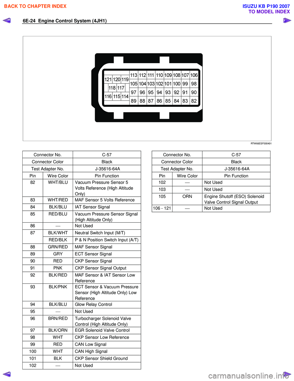
RTW 66ESF000401
Connector No. C-57
Connector Color Black
Test Adapter No. J-35616-64A
Pin W ire Color Pin Function
82 W HT/BLU Vacuum Pressure Sensor 5
Volts Reference (High Altitude
Only)
83 W HT/RED MAF Sensor 5 Volts Reference
84 BLK/BLU IAT Sensor Signal
85 RED/BLU Vacuum Pressure Sensor Signal (High Altitude Only)
86 Not Used
BLK/W HT Neutral Switch Input (M/T) 87
RED/BLK P & N Position Switch Input (A/T)
88 GRN/RED MAF Sensor Signal
89 GRY ECT Sensor Signal
90 RED CKP Sensor Signal
91 PNK CKP Sensor Signal Output
92 BLK/RED MAF Sensor & IAT Sensor Low Reference
93 BLK/PNK ECT Sensor & Vacuum Pressure Sensor (High Altitude Only) Low
Reference
94 BLK/BLU Glow Relay Control
95 Not Used
96 BRN/RED Turbocharger Solenoid Valve
Control (High Altitude Only)
97 BLK/ORN EGR Solenoid Valve Control
98 W HT CKP Sensor Low Reference
99 RED CAN Low Signal
100 W HT CAN High Signal
101 BLK CKP Sensor Shield Ground
102 Not Used
Connector No. C-57
Connector Color Black
Test Adapter No. J-35616-64A
Pin W ire Color Pin Function
102 Not Used
103 Not Used
105 ORN Engine Shutoff (ESO) Solenoid
Valve Control Signal Output
106 - 121 Not Used
BACK TO CHAPTER INDEX
TO MODEL INDEX
ISUZU KB P190 2007
Page 1060 of 6020
6E-26 Engine Control System (4JH1)
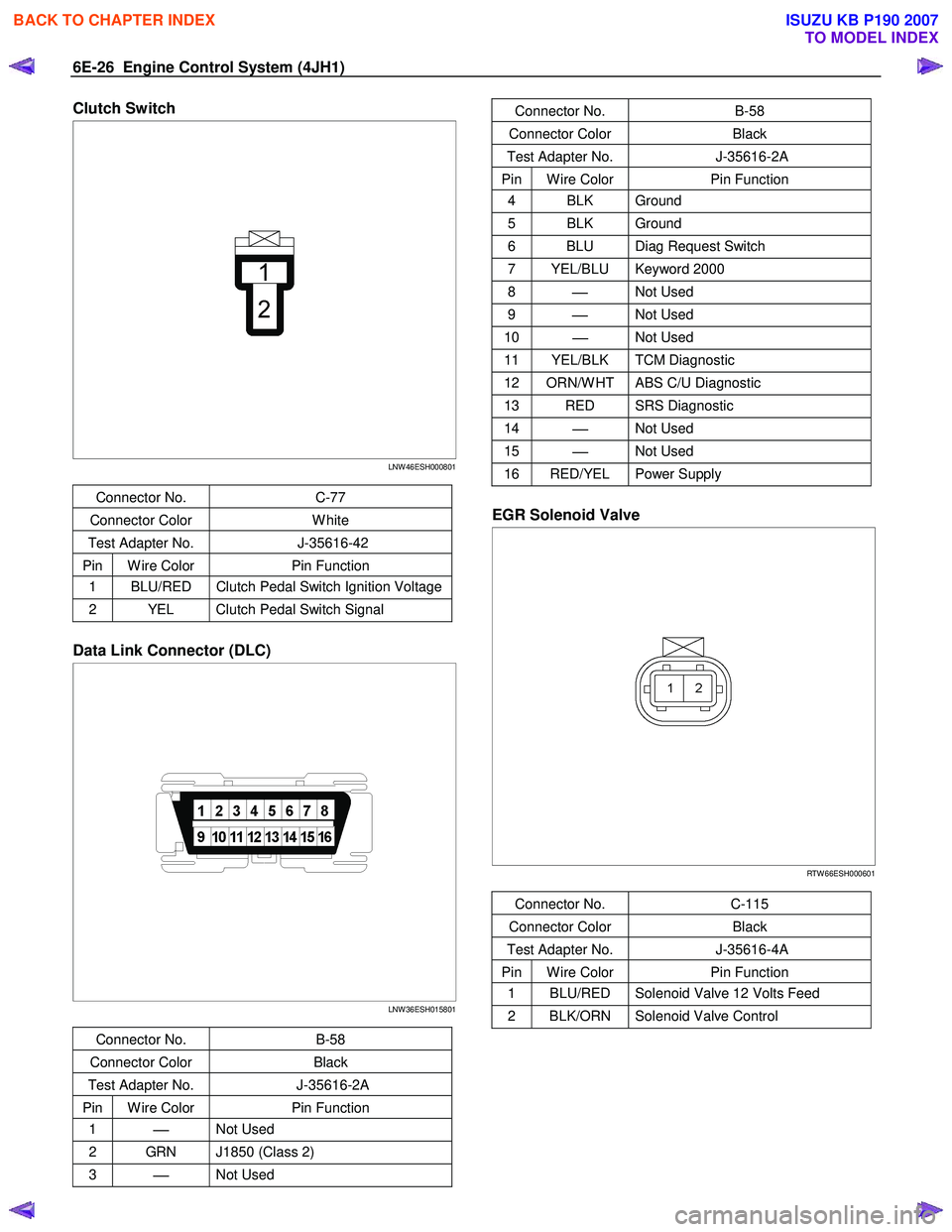
Clutch Switch
LNW 46ESH000801
Connector No. C-77
Connector Color W hite
Test Adapter No. J-35616-42
Pin W ire Color Pin Function
1 BLU/RED Clutch Pedal Switch Ignition Voltage
2 YEL Clutch Pedal Switch Signal
Data Link Connector (DLC)
LNW 36ESH015801
Connector No. B-58
Connector Color Black
Test Adapter No. J-35616-2A
Pin W ire Color Pin Function
1
Not Used
2 GRN J1850 (Class 2)
3
Not Used
Connector No. B-58
Connector Color Black
Test Adapter No. J-35616-2A
Pin W ire Color Pin Function
4 BLK Ground
5 BLK Ground
6 BLU Diag Request Switch
7 YEL/BLU Keyword 2000
8
Not Used
9
Not Used
10
Not Used
11 YEL/BLK TCM Diagnostic
12 ORN/W HT ABS C/U Diagnostic
13 RED SRS Diagnostic
14
Not Used
15
Not Used
16 RED/YEL Power Supply
EGR Solenoid Valve
RTW 66ESH000601
Connector No. C-115
Connector Color Black
Test Adapter No. J-35616-4A
Pin W ire Color Pin Function
1 BLU/RED Solenoid Valve 12 Volts Feed
2 BLK/ORN Solenoid Valve Control
BACK TO CHAPTER INDEX
TO MODEL INDEX
ISUZU KB P190 2007
Page 1070 of 6020
6E-36 Engine Control System (4JH1)
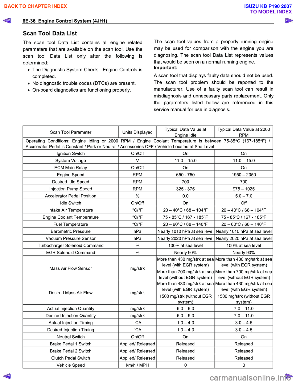
Scan Tool Data List
The scan tool Data List contains all engine related
parameters that are available on the scan tool. Use the
scan tool Data List only after the following is
determined: • The Diagnostic System Check - Engine Controls is
completed.
• No diagnostic trouble codes (DTCs) are present.
• On-board diagnostics are functioning properly.
The scan tool values from a properly running engine
may be used for comparison with the engine you are
diagnosing. The scan tool Data List represents values
that would be seen on a normal running engine.
Important:
A scan tool that displays faulty data should not be used.
The scan tool problem should be reported to the
manufacturer. Use of a faulty scan tool can result in
misdiagnosis and unnecessary parts replacement. Onl
y
the parameters listed below are referenced in this
service manual for use in diagnosis.
Scan Tool Parameter Units DisplayedTypical Data Value at
Engine Idle
Typical Data Value at 2000
RPM
Operating Conditions: Engine Idling or 2000 RPM / Engine Coolant Temperature is between 75-85 °C (167-185 °F) /
Accelerator Pedal is Constant / Park or Neutral / Accessories OFF / Vehicle Located at Sea Level
Ignition Switch On/Off On On
System Voltage V 11.0 – 15.0 11.0 – 15.0
ECM Main Relay On/Off On On
Engine Speed RPM 650 - 750 1950 – 2050
Desired Idle Speed RPM 700 700
Injection Pump Speed RPM 325 - 375 975 – 1025
Accelerator Pedal Position % 0.0 5.0 – 7.0
Idle Switch On/Off On Off
Intake Air Temperature °C/°F 20 – 40°C / 68 – 104°F 20 – 40°C / 68 – 104°F
Engine Coolant Temperature °C/°F 75 - 85 °C / 167 - 185 °F 75 - 85 °C / 167 - 185 °F
Fuel Temperature °C/°F 20 – 60°C / 68 – 140°F 20 – 60°C / 68 – 140°F
Barometric Pressure hPa Nearly 1010 hPa at sea level Nearly 1010 hPa at sea level
Vacuum Pressure Sensor hPa Nearly 2020 hPa at sea level Nearly 2020 hPa at sea level
Turbocharger Solenoid Command % 100% at sea level 100% at sea level
EGR Solenoid Command % Nearly 90% Nearly 90%
Mass Air Flow Sensor mg/strk
More than 430 mg/strk at sea
level (with EGR system)
More than 700 mg/strk at sea
level (without EGR system)
More than 430 mg/strk at sea
level (with EGR system)
More than 700 mg/strk at sea
level (without EGR system)
Desired Mass Air Flow mg/strk
More than 430 mg/strk at sea
level (with EGR system)
1500 mg/strk (without EGR
system)
More than 430 mg/strk at sea
level (with EGR system)
1500 mg/strk (without EGR
system)
Actual Injection Quantity mg/strk 6.0 – 9.0 7.0 – 11.0
Desired Injection Quantity mg/strk 6.0 – 9.0 7.0 – 11.0
Actual Injection Timing °CA 1.0 – 4.0 3.0 – 4.5
Desired Injection Timing °CA 1.0 – 4.0 3.0 – 4.5
Neutral Switch On/Off On On
Brake Pedal 1 Switch Applied/ ReleasedReleased Released
Brake Pedal 2 Switch Applied/ ReleasedReleased Released
Clutch Pedal Switch Applied/ ReleasedReleased Released
Vehicle Speed km/h / MPH 0 0
BACK TO CHAPTER INDEX
TO MODEL INDEX
ISUZU KB P190 2007
Page 1072 of 6020
6E-38 Engine Control System (4JH1)
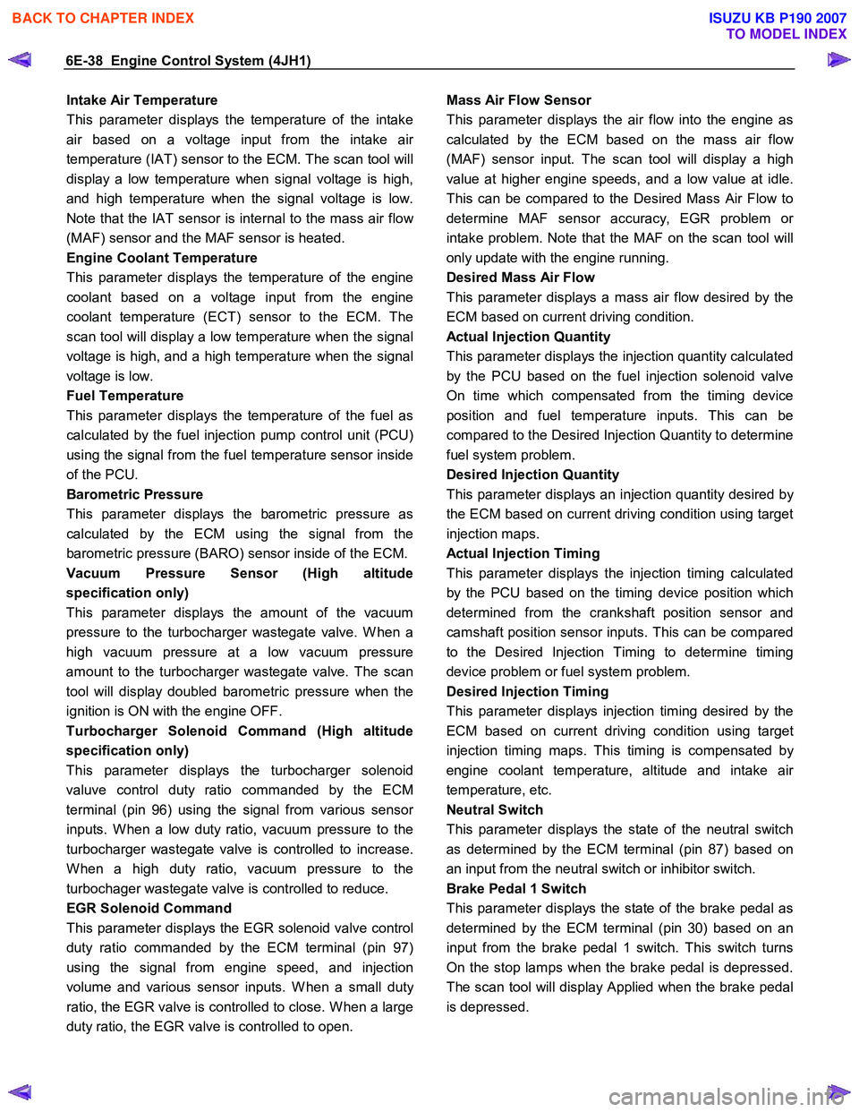
Intake Air Temperature
This parameter displays the temperature of the intake
air based on a voltage input from the intake ai
r
temperature (IAT) sensor to the ECM. The scan tool will
display a low temperature when signal voltage is high,
and high temperature when the signal voltage is low.
Note that the IAT sensor is internal to the mass air flo
w
(MAF) sensor and the MAF sensor is heated.
Engine Coolant Temperature
This parameter displays the temperature of the engine
coolant based on a voltage input from the engine
coolant temperature (ECT) sensor to the ECM. The
scan tool will display a low temperature when the signal
voltage is high, and a high temperature when the signal
voltage is low.
Fuel Temperature
This parameter displays the temperature of the fuel as
calculated by the fuel injection pump control unit (PCU)
using the signal from the fuel temperature sensor inside
of the PCU.
Barometric Pressure
This parameter displays the barometric pressure as
calculated by the ECM using the signal from the
barometric pressure (BARO) sensor inside of the ECM.
Vacuum Pressure Sensor (High altitude
specification only)
This parameter displays the amount of the vacuum
pressure to the turbocharger wastegate valve. W hen a
high vacuum pressure at a low vacuum pressure
amount to the turbocharger wastegate valve. The scan
tool will display doubled barometric pressure when the
ignition is ON with the engine OFF.
Turbocharger Solenoid Command (High altitude
specification only)
This parameter displays the turbocharger solenoid
valuve control duty ratio commanded by the ECM
terminal (pin 96) using the signal from various senso
r
inputs. W hen a low duty ratio, vacuum pressure to the
turbocharger wastegate valve is controlled to increase.
W hen a high duty ratio, vacuum pressure to the
turbochager wastegate valve is controlled to reduce.
EGR Solenoid Command
This parameter displays the EGR solenoid valve control
duty ratio commanded by the ECM terminal (pin 97)
using the signal from engine speed, and injection
volume and various sensor inputs. W hen a small dut
y
ratio, the EGR valve is controlled to close. W hen a large
duty ratio, the EGR valve is controlled to open.
Mass Air Flow Sensor
This parameter displays the air flow into the engine as
calculated by the ECM based on the mass air flo
w
(MAF) sensor input. The scan tool will display a high
value at higher engine speeds, and a low value at idle.
This can be compared to the Desired Mass Air Flow to
determine MAF sensor accuracy, EGR problem o
r
intake problem. Note that the MAF on the scan tool will
only update with the engine running.
Desired Mass Air Flow
This parameter displays a mass air flow desired by the
ECM based on current driving condition.
Actual Injection Quantity
This parameter displays the injection quantity calculated
by the PCU based on the fuel injection solenoid valve
On time which compensated from the timing device
position and fuel temperature inputs. This can be
compared to the Desired Injection Quantity to determine
fuel system problem.
Desired Injection Quantity
This parameter displays an injection quantity desired b
y
the ECM based on current driving condition using target
injection maps.
Actual Injection Timing
This parameter displays the injection timing calculated
by the PCU based on the timing device position which
determined from the crankshaft position sensor and
camshaft position sensor inputs. This can be compared
to the Desired Injection Timing to determine timing
device problem or fuel system problem.
Desired Injection Timing
This parameter displays injection timing desired by the
ECM based on current driving condition using target
injection timing maps. This timing is compensated b
y
engine coolant temperature, altitude and intake ai
r
temperature, etc.
Neutral Switch
This parameter displays the state of the neutral switch
as determined by the ECM terminal (pin 87) based on
an input from the neutral switch or inhibitor switch.
Brake Pedal 1 Switch
This parameter displays the state of the brake pedal as
determined by the ECM terminal (pin 30) based on an
input from the brake pedal 1 switch. This switch turns
On the stop lamps when the brake pedal is depressed.
The scan tool will display Applied when the brake pedal
is depressed.
BACK TO CHAPTER INDEX
TO MODEL INDEX
ISUZU KB P190 2007
Page 1074 of 6020
6E-40 Engine Control System (4JH1)
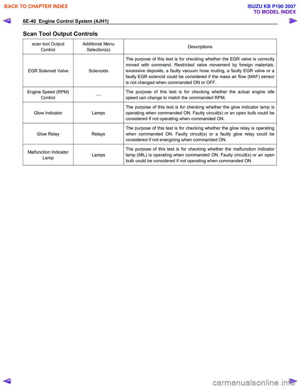
Scan Tool Output Controls
scan tool Output Control Additional Menu
Selection(s) Descriptions
EGR Solenoid Valve Solenoids The purpose of this test is for checking whether the EGR valve is correctly
moved with command. Restricted valve movement by foreign materials,
excessive deposits, a faulty vacuum hose routing, a faulty EGR valve or a
faulty EGR solenoid could be considered if the mass air flow (MAF) sensor
is not changed when commanded ON or OFF.
Engine Speed (RPM) Control
The purpose of this test is for checking whether the actual engine idle
speed can change to match the commanded RPM.
Glow Indicator Lamps The purpose of this test is for checking whether the glow indicator lamp is
operating when commanded ON. Faulty circuit(s) or an open bulb could be
considered if not operating when commanded ON.
Glow Relay Relays The purpose of this test is for checking whether the glow relay is operating
when commanded ON. Faulty circuit(s) or a faulty glow relay could be
considered if not energizing when commanded ON.
Malfunction Indicator Lamp Lamps The purpose of this test is for checking whether the malfunction indicator
lamp (MIL) is operating when commanded ON. Faulty circuit(s) or an open
bulb could be considered if not operating when commanded ON.
BACK TO CHAPTER INDEX
TO MODEL INDEX
ISUZU KB P190 2007
Page 1087 of 6020
Engine Control System (4JH1) 6E-53
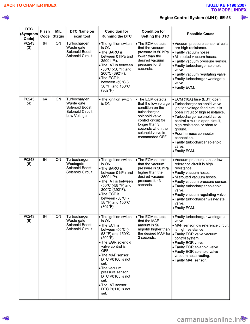
DTC
(Symptom Code) Flash
Code MIL
Status DTC Name on
scan tool Condition for
Running the DTC Condition for
Setting the DTC Possible Cause
P0243
(3) 64 ON Turbocharger
W aste gate
Solenoid Boost
Solenoid Circuit •
The ignition switch
is ON.
• The BARO is
between 0 hPa and
3500 hPa.
• The IAT is between
-50°C (-58 °F) and
200°C (392°F).
• The ECT is
between -50°C (-
58 °F) and 150°C
(302°F).
•
The ECM detects
that the vacuum
pressure is 50 hPa
lower than the
desired vacuum
pressure for 3
seconds.
•
Vacuum pressure sensor circuits
are high resistance.
• Faulty vacuum hoses
• Misrouted vacuum hoses.
• Faulty vacuum pressure sensor.
• Faulty turbocharger solenoid
valve.
• Faulty vacuum regulating valve.
• Faulty turbocharger wastegate
valve.
• Faulty ECM.
P0243 (4) 64 ON Turbocharger
W aste gate
Solenoid Boost
Solenoid Circuit
Low Voltage •
The ignition switch
is ON.
•
The ECM detects
that the low voltage
condition on the
turbocharger
solenoid valve
control circuit for
longer than 3
seconds when the
solenoid valve is
commanded OFF.
•
ECM (10A) fuse (EB1) open.
• Turbocharger solenoid valve
ignition voltage feed circuit is
open circuit or high resistance.
• Turbocharger solenoid valve
control circuit is open circuit,
high resistance or short to
ground.
• Poor harness connector
connection.
• Faulty turbocharger solenoid
valve.
• Faulty ECM.
P0243 (5) 64 ON Turbocharger
W astegate
Solenoid Boost
Solenoid Circuit •
The ignition switch
is ON.
• The BARO is
between 0 hPa and
3500 hPa.
• The IAT is between
-50°C (-58 °F) and
200°C (392°F).
• The ECT is
between -50°C (-
58 °F) and 150°C
(302°F).
•
The ECM detects
that the vacuum
pressure is 50 hPa
higher than the
desired vacuum
pressure for 3
seconds.
•
Vacuum pressure sensor low
reference circuit is high
resistance.
• Faulty vacuum hoses
• Misrouted vacuum hoses.
• Faulty vacuum pressure sensor.
• Faulty turbocharger solenoid
valve.
• Faulty vacuum regulating valve.
• Faulty turbocharger wastegate
valve.
• Faulty ECM.
P0243 (6) 64 ON Turbocharger
W aste gate
Solenoid Boost
Solenoid Circuit •
The ignition switch
is ON.
• The ECT is
between -50°C (-
58 °F) and 150°C
(302°F).
• The EGR solenoid
valve control is
OFF.
• The MAF sensor
DTC P0100 is not
set.
• The vacuum
pressure sensor
DTC P0105 is not
set.
• The IAT sensor
DTC P0110 is not
set.
•
The ECM detects
that the MAF
amount is 56
mg/strk higher than
the desired MAF for
3 seconds.
•
Faulty turbocharger wastegate
valve.
• MAF sensor low reference circuit
is high resistance.
• Faulty EGR valve vacuum
control system.
• Faulty EGR valve.
• Faulty EGR solenoid valve.
• Faulty EGR solenoid valve
vacuum hose routing.
• Faulty MAF sensor.
BACK TO CHAPTER INDEX
TO MODEL INDEX
ISUZU KB P190 2007
Page 1090 of 6020
6E-56 Engine Control System (4JH1)
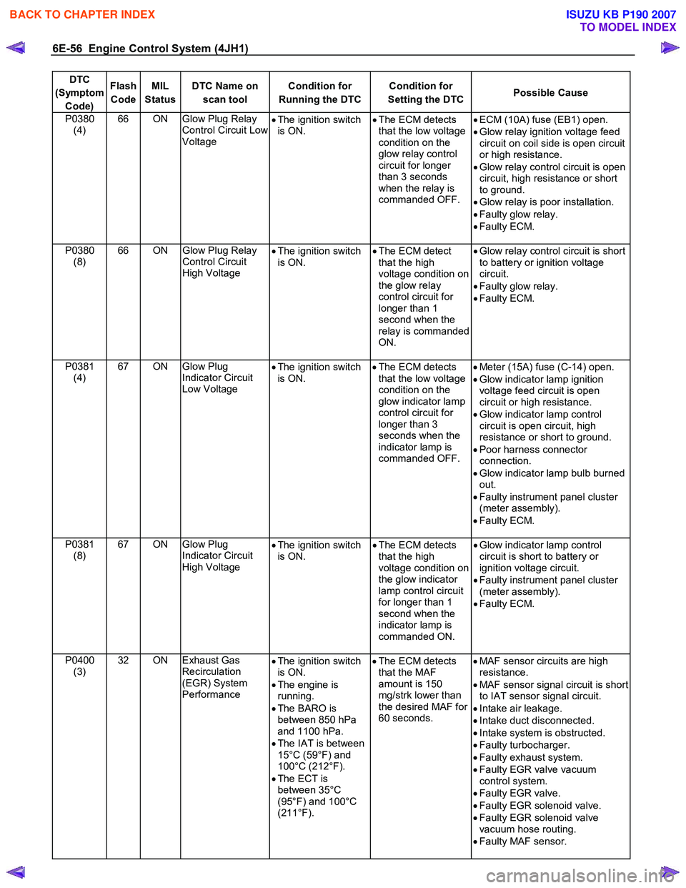
DTC
(Symptom Code) Flash
Code MIL
Status DTC Name on
scan tool Condition for
Running the DTC Condition for
Setting the DTC Possible Cause
P0380
(4) 66 ON Glow Plug Relay
Control Circuit Low
Voltage •
The ignition switch
is ON. •
The ECM detects
that the low voltage
condition on the
glow relay control
circuit for longer
than 3 seconds
when the relay is
commanded OFF.
•
ECM (10A) fuse (EB1) open.
• Glow relay ignition voltage feed
circuit on coil side is open circuit
or high resistance.
• Glow relay control circuit is open
circuit, high resistance or short
to ground.
• Glow relay is poor installation.
• Faulty glow relay.
• Faulty ECM.
P0380 (8) 66 ON
Glow Plug Relay
Control Circuit
High Voltage •
The ignition switch
is ON. •
The ECM detect
that the high
voltage condition on
the glow relay
control circuit for
longer than 1
second when the
relay is commanded
ON.
•
Glow relay control circuit is short
to battery or ignition voltage
circuit.
• Faulty glow relay.
• Faulty ECM.
P0381 (4) 67 ON Glow Plug
Indicator Circuit
Low Voltage •
The ignition switch
is ON.
•
The ECM detects
that the low voltage
condition on the
glow indicator lamp
control circuit for
longer than 3
seconds when the
indicator lamp is
commanded OFF.
•
Meter (15A) fuse (C-14) open.
• Glow indicator lamp ignition
voltage feed circuit is open
circuit or high resistance.
• Glow indicator lamp control
circuit is open circuit, high
resistance or short to ground.
• Poor harness connector
connection.
• Glow indicator lamp bulb burned
out.
• Faulty instrument panel cluster
(meter assembly).
• Faulty ECM.
P0381 (8) 67 ON Glow Plug
Indicator Circuit
High Voltage •
The ignition switch
is ON. •
The ECM detects
that the high
voltage condition on
the glow indicator
lamp control circuit
for longer than 1
second when the
indicator lamp is
commanded ON.
•
Glow indicator lamp control
circuit is short to battery or
ignition voltage circuit.
• Faulty instrument panel cluster
(meter assembly).
• Faulty ECM.
P0400 (3) 32 ON Exhaust Gas
Recirculation
(EGR) System
Performance •
The ignition switch
is ON.
• The engine is
running.
• The BARO is
between 850 hPa
and 1100 hPa.
• The IAT is between
15°C (59°F) and
100°C (212°F).
• The ECT is
between 35°C
(95°F) and 100°C
(211°F).
•
The ECM detects
that the MAF
amount is 150
mg/strk lower than
the desired MAF for
60 seconds.
•
MAF sensor circuits are high
resistance.
• MAF sensor signal circuit is short
to IAT sensor signal circuit.
• Intake air leakage.
• Intake duct disconnected.
• Intake system is obstructed.
• Faulty turbocharger.
• Faulty exhaust system.
• Faulty EGR valve vacuum
control system.
• Faulty EGR valve.
• Faulty EGR solenoid valve.
• Faulty EGR solenoid valve
vacuum hose routing.
• Faulty MAF sensor.
BACK TO CHAPTER INDEX
TO MODEL INDEX
ISUZU KB P190 2007
Page 1091 of 6020
Engine Control System (4JH1) 6E-57
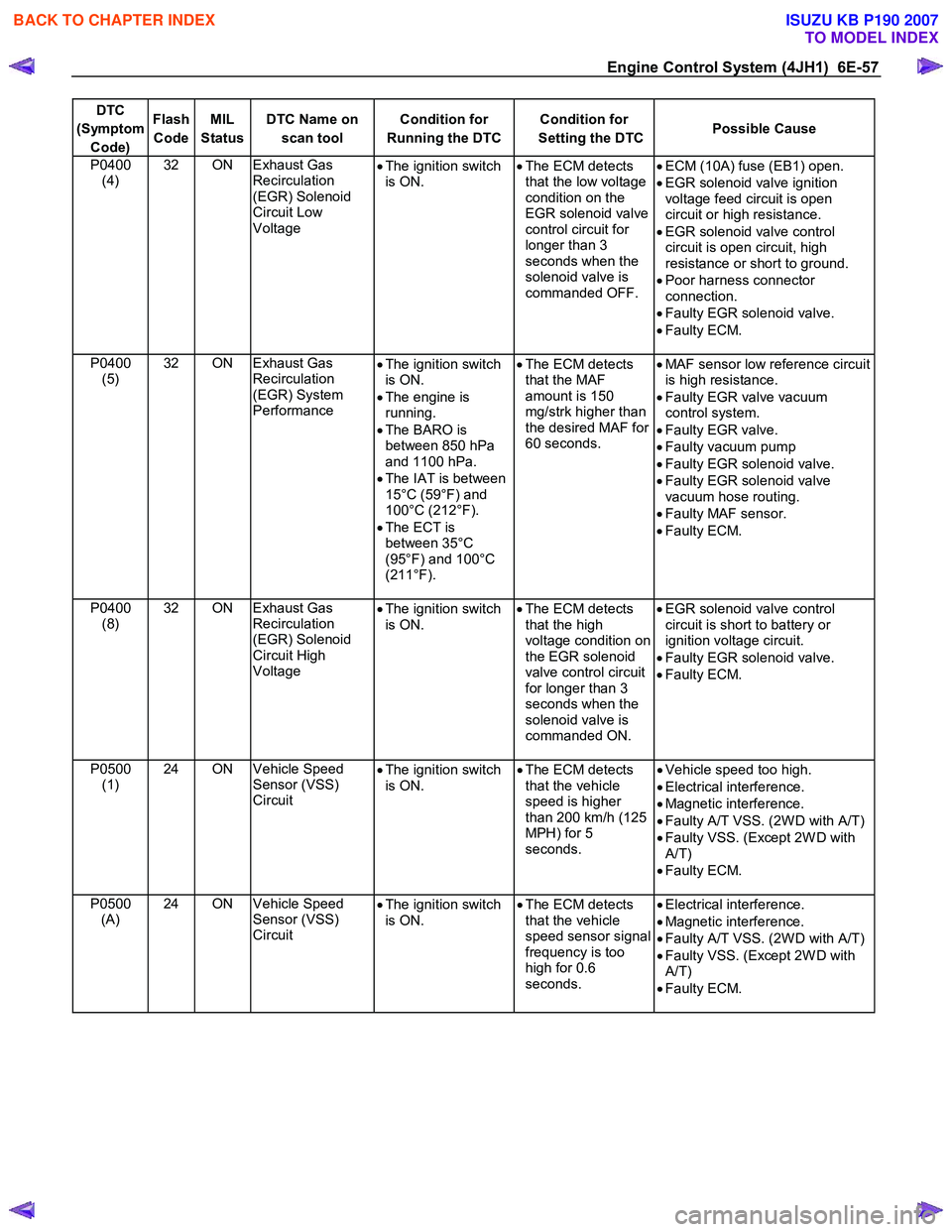
DTC
(Symptom Code) Flash
Code MIL
Status DTC Name on
scan tool Condition for
Running the DTC Condition for
Setting the DTC Possible Cause
P0400
(4) 32 ON Exhaust Gas
Recirculation
(EGR) Solenoid
Circuit Low
Voltage •
The ignition switch
is ON.
•
The ECM detects
that the low voltage
condition on the
EGR solenoid valve
control circuit for
longer than 3
seconds when the
solenoid valve is
commanded OFF.
•
ECM (10A) fuse (EB1) open.
• EGR solenoid valve ignition
voltage feed circuit is open
circuit or high resistance.
• EGR solenoid valve control
circuit is open circuit, high
resistance or short to ground.
• Poor harness connector
connection.
• Faulty EGR solenoid valve.
• Faulty ECM.
P0400 (5) 32 ON Exhaust Gas
Recirculation
(EGR) System
Performance •
The ignition switch
is ON.
• The engine is
running.
• The BARO is
between 850 hPa
and 1100 hPa.
• The IAT is between
15°C (59°F) and
100°C (212°F).
• The ECT is
between 35°C
(95°F) and 100°C
(211°F).
•
The ECM detects
that the MAF
amount is 150
mg/strk higher than
the desired MAF for
60 seconds.
•
MAF sensor low reference circuit
is high resistance.
• Faulty EGR valve vacuum
control system.
• Faulty EGR valve.
• Faulty vacuum pump
• Faulty EGR solenoid valve.
• Faulty EGR solenoid valve
vacuum hose routing.
• Faulty MAF sensor.
• Faulty ECM.
P0400 (8) 32 ON Exhaust Gas
Recirculation
(EGR) Solenoid
Circuit High
Voltage
•
The ignition switch
is ON.
•
The ECM detects
that the high
voltage condition on
the EGR solenoid
valve control circuit
for longer than 3
seconds when the
solenoid valve is
commanded ON.
•
EGR solenoid valve control
circuit is short to battery or
ignition voltage circuit.
• Faulty EGR solenoid valve.
• Faulty ECM.
P0500 (1) 24 ON Vehicle Speed
Sensor (VSS)
Circuit
•
The ignition switch
is ON. •
The ECM detects
that the vehicle
speed is higher
than 200 km/h (125
MPH) for 5
seconds.
•
Vehicle speed too high.
• Electrical interference.
• Magnetic interference.
• Faulty A/T VSS. (2W D with A/T)
• Faulty VSS. (Except 2W D with
A/T)
• Faulty ECM.
P0500 (A) 24 ON Vehicle Speed
Sensor (VSS)
Circuit
•
The ignition switch
is ON. •
The ECM detects
that the vehicle
speed sensor signal
frequency is too
high for 0.6
seconds. •
Electrical interference.
• Magnetic interference.
• Faulty A/T VSS. (2W D with A/T)
• Faulty VSS. (Except 2W D with
A/T)
• Faulty ECM.
BACK TO CHAPTER INDEX
TO MODEL INDEX
ISUZU KB P190 2007