Page 5746 of 6020

9A1-64 RESTRAINT CONTROL SYSTEM
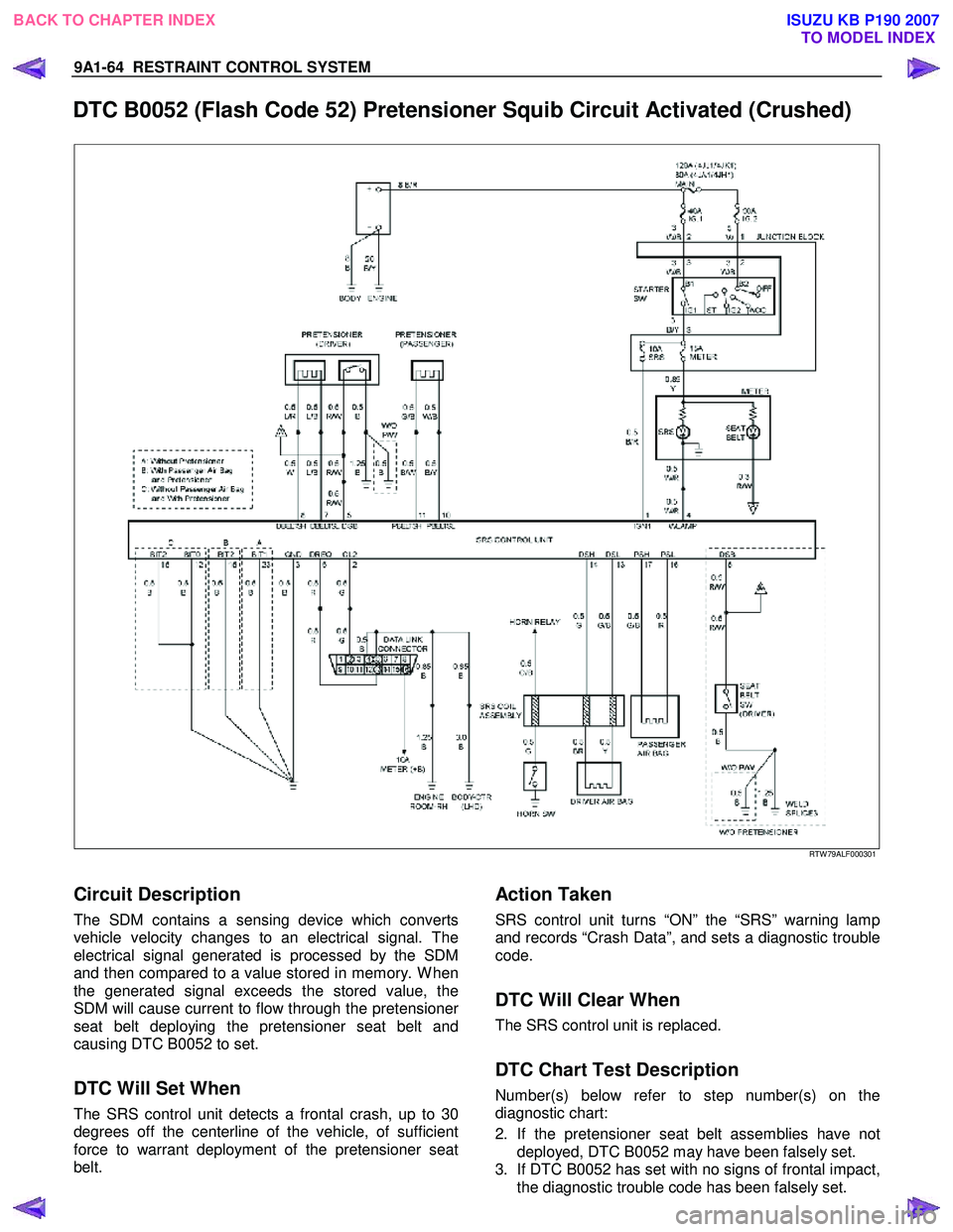
DTC B0052 (Flash Code 52) Pretensioner Squib Circuit Activated (Crushed)
RTW 79ALF000301
Circuit Description
The SDM contains a sensing device which converts
vehicle velocity changes to an electrical signal. The
electrical signal generated is processed by the SDM
and then compared to a value stored in memory. W hen
the generated signal exceeds the stored value, the
SDM will cause current to flow through the pretensione
r
seat belt deploying the pretensioner seat belt and
causing DTC B0052 to set.
DTC Will Set When
The SRS control unit detects a frontal crash, up to 30
degrees off the centerline of the vehicle, of sufficient
force to warrant deployment of the pretensioner seat
belt.
Action Taken
SRS control unit turns “ON” the “SRS” warning lamp
and records “Crash Data”, and sets a diagnostic trouble
code.
DTC Will Clear When
The SRS control unit is replaced.
DTC Chart Test Description
Number(s) below refer to step number(s) on the
diagnostic chart:
2. If the pretensioner seat belt assemblies have not deployed, DTC B0052 may have been falsely set.
3. If DTC B0052 has set with no signs of frontal impact, the diagnostic trouble code has been falsely set.
BACK TO CHAPTER INDEX TO MODEL INDEX
ISUZU KB P190 2007
Page 5873 of 6020

11A-22 IMMOBILIZER CONTROL SYSTEM (4JK1/4JJ1/HFV6)
DTC B0001
Description
This diagnostic applies to internal microprocessor
integrity conditions within the ICU.
Condition for Setting the DTC • The ECM detects a faulty writing in its internal electrically erasable & programmable read only
memory (EEPROM). Action Taken When the DTC Sets
• The engine will fail to run if the fault occurs before starting the engine.
Condition for Clearing the DTC • A current DTC clears once ignition cycle has occurred without the fault recurring.
• A history DTC will clear after 50 consecutive ignition cycles, if the condition for malfunction is no
longer present.
• Use a scan tool to clear the DTC.
Circuit/ System Testing DTC B0001
Step Action Value(s)Yes No
1 Did you perform the Diagnostic System Check -
Immobilizer Controls? —
Go to Step 2 Go to Diagnostic
System Check - Immobilizer
Controls
2 1. Install a scan tool.
2. Turn OFF the ignition for 30 seconds.
3. Turn ON the ignition, with the engine OFF.
4. Monitor the DTC Information with a scan tool.
Does the DTC fail this ignition? —
Go to Step 3 Go to Step 4
3 Important
: Replacement ICU must be
programmed.
Replace the ICU. Refer to ICU Replacement.
Did you complete the replacement? —
Go to Step 4
—
41. Clear the DTCs with a scan tool.
2. Turn OFF the ignition for 30 seconds.
3. Turn ON the ignition.
Did the DTC fail this ignition? —
Go to Step 3 Go to Step 5
5 Observe the DTC Information with a scan tool.
Are there any DTCs that you have not diagnosed? —
Go to DTC List System OK
BACK TO CHAPTER INDEX
TO MODEL INDEX
ISUZU KB P190 2007
Page 5957 of 6020

ANTITHEFT SYSTEM 11B-3
Function of a keyless entry system
W ith a keyless entry system the car can be locked or
unlocked from any position around the car up to a
specified distance, by using the potable radio remote
transmitter inside key (remote key).
Status LED
W hile the system is in delay the alarm system is active
and LED flashes at 0.5Hz with or without activated
interior protection.
Hazard relay
The hazard warning lights will be activated by an
external relay. The output is low active.
Switches
All switches to ground. This makes it possible for failure
analysis to detect a short circuit or a broken wire to
each switch. To use this feature it is necessary to place
a 1.8k Ω resistor in parallel to the required switch.
Receiver
The receiver is integrated into the control unit.
To lower the idle current the receiver is equipped with a
standby mode. The antenna is integrated on the printed
circuit board.
Depending on the mounting position of the control unit
the antenna can be connected externally.
Range of communication
The range of communication between remote key and
receiver is intended to be least 3 m from centre of the
car.
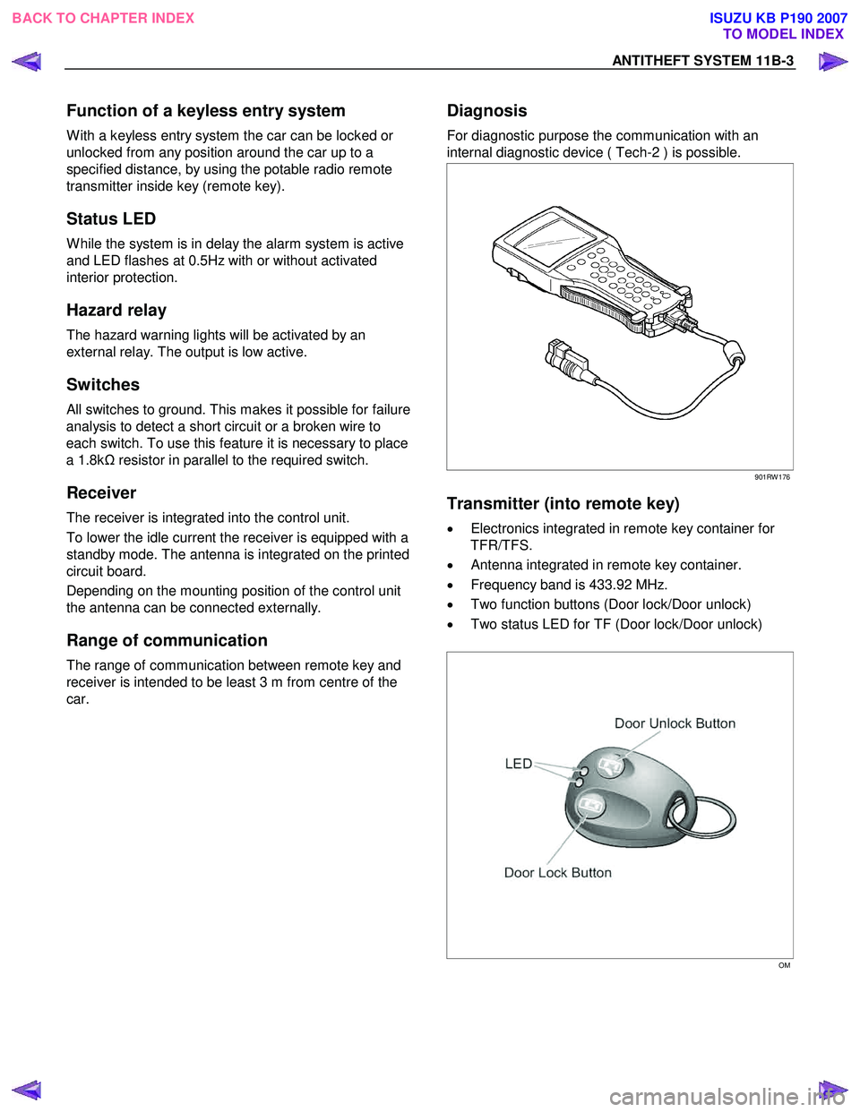
Diagnosis
For diagnostic purpose the communication with an
internal diagnostic device ( Tech-2 ) is possible.
901RW 176
Transmitter (into remote key)
• Electronics integrated in remote key container for
TFR/TFS.
• Antenna integrated in remote key container.
• Frequency band is 433.92 MHz.
• Two function buttons (Door lock/Door unlock)
• Two status LED for TF (Door lock/Door unlock)
OM
BACK TO CHAPTER INDEX TO MODEL INDEX
ISUZU KB P190 2007