Page 4940 of 6020

8A-2 ELECTRICAL-BODY AND CHASSIS
PAGE
Fuse Block Circuit (4JJ1-TC/4JK1-TC (RHD)) SOUTH AFRICA ...............................8A- 39
Fuse Block Circuit (4JJ1-TC/4JK1-TC (RHD)) EXCEPT SOUTH AFRICA ...............8A- 41
Fuse Block Circuit (4JJ1-TC/4JK1-TC) - (LHD) G.EXP .............................................8A- 43
Fuse Block Circuit (4JH1-TC) - (LHD) ........................................................................8A- 45
Fuse Block Circuit (4JA1T (L)) ...................................................................................8A- 47
Grounding Point ..............................................................................................................8 A- 49
Ground Point ...............................................................................................................8A- 49
Ground Point Location ...............................................................................................8A- 89
Cable Harness Routing ...................................................................................................8A- 91
Main Cable Harness (RHD)..........................................................................................8A- 91
Instrument Harness (RHD) ..........................................................................................8A- 92
Main Cable Harness (LHD) ..........................................................................................8A- 93
Instrument Harness (LHD) ..........................................................................................8A- 94
Engine Harness C24SE ...............................................................................................8A- 95
Engine Harness 4JJ1-TC/4JK1-TC ............................................................................8A- 96
Engine Harness 4JH1-TC/4JA1T (L) ...........................................................................8A- 97
Transmission Harness ...............................................................................................8A- 98
System Repair ................................................................................................................. .8A- 100
Start and Charging ......................................................................................................8A- 10 0
Engine Control Module (ECM) ...................................................................................8A- 111
Exhaust Gas Recirculation (EGR) & GLOW; 4JA1T (L) Only ...................................8A- 143
Lighting ...................................................................................................................... ..8A- 149
Front Fog Light ...........................................................................................................8A- 180
Rear Fog Light ............................................................................................................8A- 190
Headlight Leveling ......................................................................................................8A- 19 4
Illumination .................................................................................................................. 8A- 200
Hazard Warning Flasher, Turn Signal Light, Backup Light, Horn and Stoplight ....................................................................................................8A- 213
Dome Light, Spotlight, Map Light and Warning Buzzer ..........................................8A- 245
Windshield Wiper and Washer ..................................................................................8A- 264
Transmission Control Module (TCM) ........................................................................8A- 285
Manual Transmission Shift Assist .............................................................................8A- 298
Meter, Warning Light and Indicator Light .................................................................8A- 303
Heater and Air Conditioning ......................................................................................8A- 371
Power Door Lock ........................................................................................................8A- 386
BACK TO CHAPTER INDEX
TO MODEL INDEX
ISUZU KB P190 2007
Page 4950 of 6020

8A-12 ELECTRICAL-BODY AND CHASSIS
ABBREVIATIONS
Abbreviation Meaning of abbreviation Abbreviation Meaning of abbreviation
A Ampere (S) kW Kilowatt
ABS Anti-lock brake system LH Left hand
ASM Assembly LW B Long wheel base
AC Alternating current MPI Multipart fuel injection
A/C Air conditioner M/T Manual transmission
ACC Accessories PA Passenger
CARB Carburetor PIM Power train interface module
C/B Circuit breaker PJT Projector
CKP Crankshaft position QOS Quick On Start system
CSD Cold start device RH Right hand
DIS Direct ignition system RR Rear
DR Driver RW AL Rear wheel anti-lock brake system
DRM Data Recording Module SCV Suction control valve
EHCU Electronic Hydraulic control Unit SRS Supplemental restraint system
ECGI Electronic control gasoline injection ST Start
ECM Engine control module STD Standard
ECU Electronic control unit SW Switch
EFE Early fuel evaporation SW B Short wheel base
EGR Exhaust gas recirculation TCM Transmission control module
2W D Two-wheel drive TCCM Transfer case control module
4W D Four-wheel drive V Volt
FL Fusible link VSV Vacuum switching valve
FRT Front W W att (S)
H/L Headlight W OT W ide open throttle
W/ With HVAC
Heater, Ventilation, and Air
Conditioning W /O W ithout
IC Integrated circuit W /S W eld Splice
IG Ignition
BACK TO CHAPTER INDEX
TO MODEL INDEXISUZU KB P190 2007
Page 5081 of 6020
ELECTRICAL-BODY AND CHASSIS 8A-143
EXHAUST GAS RECIRCULATION (EGR) & GLOW; 4JA1T (L) ONLY
PARTS LOCATION (RHD)
RTW 78AXF036501 & RTW 78AMF001101
BACK TO CHAPTER INDEX TO MODEL INDEXISUZU KB P190 2007
Page 5137 of 6020
ELECTRICAL-BODY AND CHASSIS 8A-199
HEADLIGHT LEVELING SWITCH
Incorrect beam angle due to load change can be corrected.
A four position switch, 0-3, can alter the beam angle through
1.7 degrees on the long wheel base model and 2.17 degrees
on the short wheel base model.
RTW 68ASH000501
Inspection
Check to see if there is any continuity between the terminals of
the leveling switch.
Replace the switch when the result of inspection is found
abnormal.
RTW 78ASH000601
Removal
Preparation:
Disconnect the battery ground cable.
1. Ventilation grille
2. Harness connector
3. Headlight leveling switch To remove the switch, push the lock from the back side of
the cluster assembly.
Installation
To install, follow the removal steps in the reverse noting the
following point.
1. Push in the switch with your fingers until it locks securely.
BACK TO CHAPTER INDEX TO MODEL INDEXISUZU KB P190 2007
Page 5175 of 6020

ELECTRICAL-BODY AND CHASSIS 8A-237
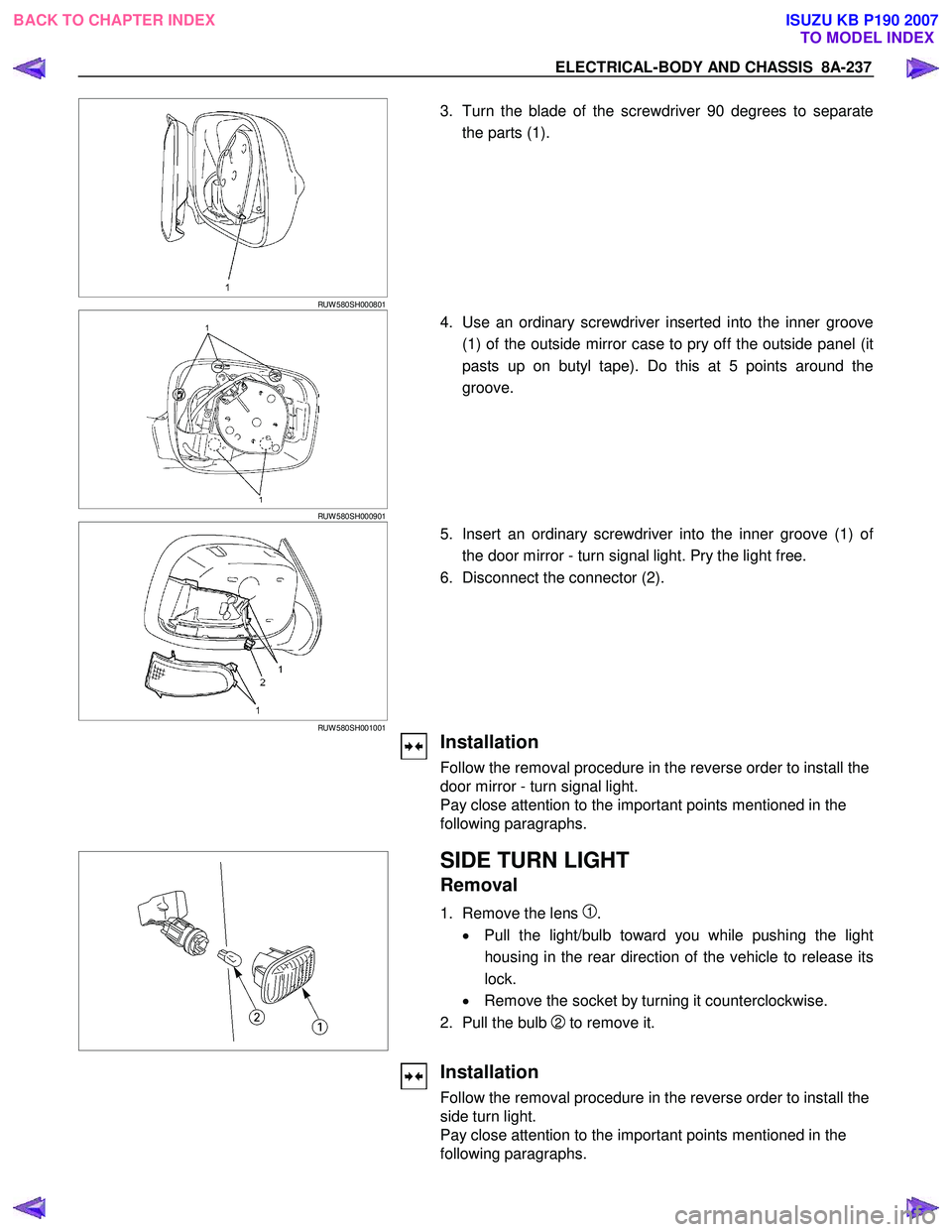
RUW 580SH000801
3. Turn the blade of the screwdriver 90 degrees to separate
the parts (1).
RUW 580SH000901
4. Use an ordinary screwdriver inserted into the inner groove
(1) of the outside mirror case to pry off the outside panel (it
pasts up on butyl tape). Do this at 5 points around the
groove.
RUW 580SH001001
5. Insert an ordinary screwdriver into the inner groove (1) of
the door mirror - turn signal light. Pry the light free.
6. Disconnect the connector (2).
Installation
Follow the removal procedure in the reverse order to install the
door mirror - turn signal light.
Pay close attention to the important points mentioned in the
following paragraphs.
SIDE TURN LIGHT
Removal
1. Remove the lens 1.
• Pull the light/bulb toward you while pushing the light
housing in the rear direction of the vehicle to release its
lock.
• Remove the socket by turning it counterclockwise.
2. Pull the bulb
2 to remove it.
Installation
Follow the removal procedure in the reverse order to install the
side turn light.
Pay close attention to the important points mentioned in the
following paragraphs.
BACK TO CHAPTER INDEX TO MODEL INDEXISUZU KB P190 2007
Page 5550 of 6020
8A-612 ELECTRICAL-BODY AND CHASSIS
No. Connector face No. Connector face
C29
Headlight leveling acutuator STD-LH C40
BlackAccelerator pedal position sensor
C30
White
Engine hood switch C41
~
C43 NOT USED
C31
Blue
EGR VSV front C44
WhiteStoplight switch
C32
Blue
EGR VSV rear C45
~
C49 NOT USED
C33
~
C34 NOT USED C50
Black
Condenser fan
C35
Gray
Side turn light-LH C51
~
C52 NOT USED
C36
Silver
Engine room-LH; ground C53
Red ABS speed sensor front-RH
C37
Black
Brake fluid level switch C54
Red ABS speed sensor front-LH
C38
Light Gray
Vacuum switch C55
BrownThermo AMP
C39
White
Parking brake switch (stick type) C56
(C24SE)
ECM
BACK TO CHAPTER INDEX TO MODEL INDEXISUZU KB P190 2007
Page 5552 of 6020
8A-614 ELECTRICAL-BODY AND CHASSIS
No. Connector face No. Connector face
C106
NOT USED C117
Black
Anti theft horn
C107
White
J/B E2 C118
A/C Resister & Neutral switch
C108
White
J/B E1 C119
~
C120 NOT USED
C109
Silver
Body-CTR; ground C121
(C24SE)
IAT sensor
C110
NOT USED C122
(C24SE)
White
Co adjuster connector
C111
Black
Transfer case control module C123
NOT USED
C112
Black
Transfer case control module C124
BlackLower pressure sensor
C113
~
C114 NOT USED C125
White
Thermo switch (Air)
C115
Brown
EVRV EGR C126
WhiteGlow control unit
C116
Black
MAF sensor C127
~
C130 NOT USED
BACK TO CHAPTER INDEX
TO MODEL INDEXISUZU KB P190 2007
Page 5557 of 6020
ELECTRICAL-BODY AND CHASSIS 8A-619
No. Connector face No. Connector face
E1
Gray
Oil pressure switch E9
Gray
T.D.C sensor
E2
(C24SE)
Magnetic clutch E10
SilverEngine ground
E3
Black
Magnetic clutch AC COMP E11
Natural greenNeutral switch
E4
Green
Generator E12
Natural greenNeutral switch
E5
TPS EGR E13
Gray Injector nozzle 1
E6
(C24SE)
Fuel injector (C24SE) E14
Gray
Injector nozzle 2
E6
Injector pump E15
Gray Injector nozzle 3
E7
(C24SE)
Fuel injector (C24SE) E16
Gray
Injector nozzle 4
E8
(C24SE)
Fuel injector (C24SE) E17
Silver
Generator (B)
E9
(C24SE)
Fuel injector (C24SE) E18
(C24SE)
Ignition coil
BACK TO CHAPTER INDEX TO MODEL INDEXISUZU KB P190 2007