2007 ISUZU KB P190 EGR
[x] Cancel search: EGRPage 3716 of 6020
Powertrain Interface Module – V6 Page 6E1–55
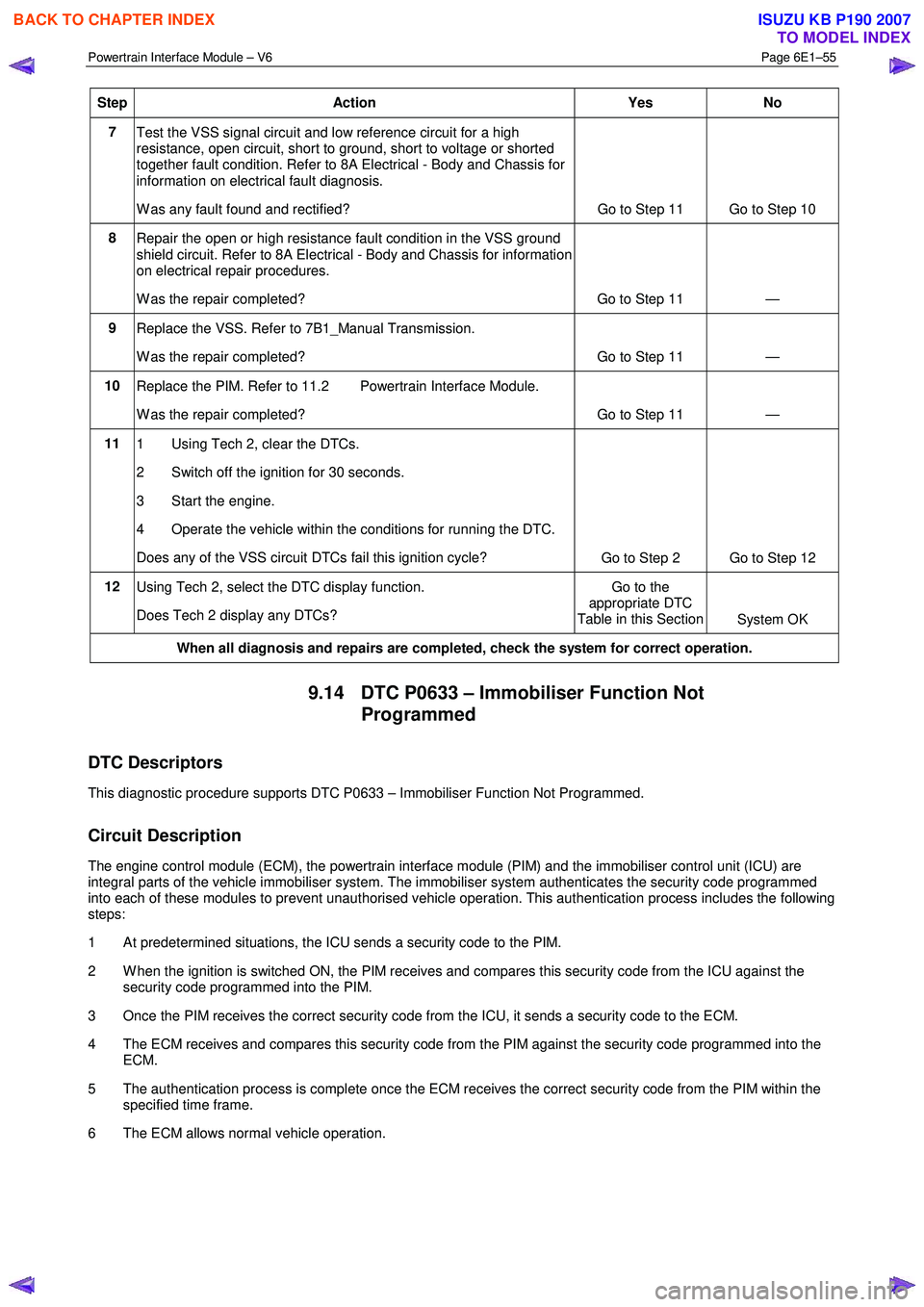
Step Action Yes No
7
Test the VSS signal circuit and low reference circuit for a high
resistance, open circuit, short to ground, short to voltage or shorted
together fault condition. Refer to 8A Electrical - Body and Chassis for
information on electrical fault diagnosis.
W as any fault found and rectified? Go to Step 11 Go to Step 10
8
Repair the open or high resistance fault condition in the VSS ground
shield circuit. Refer to 8A Electrical - Body and Chassis for information
on electrical repair procedures.
W as the repair completed? Go to Step 11 —
9 Replace the VSS. Refer to 7B1_Manual Transmission.
W as the repair completed? Go to Step 11 —
10 Replace the PIM. Refer to 11.2 Powertrain Interface Module.
W as the repair completed? Go to Step 11 —
11 1 Using Tech 2, clear the DTCs.
2 Switch off the ignition for 30 seconds.
3 Start the engine.
4 Operate the vehicle within the conditions for running the DTC.
Does any of the VSS circuit DTCs fail this ignition cycle? Go to Step 2 Go to Step 12
12
Using Tech 2, select the DTC display function.
Does Tech 2 display any DTCs? Go to the
appropriate DTC
Table in this Section System OK
When all diagnosis and repairs are completed, check the system for correct operation.
9.14 DTC P0633 – Immobiliser Function Not
Programmed
DTC Descriptors
This diagnostic procedure supports DTC P0633 – Immobiliser Function Not Programmed.
Circuit Description
The engine control module (ECM), the powertrain interface module (PIM) and the immobiliser control unit (ICU) are
integral parts of the vehicle immobiliser system. The immobiliser system authenticates the security code programmed
into each of these modules to prevent unauthorised vehicle operation. This authentication process includes the following
steps:
1 At predetermined situations, the ICU sends a security code to the PIM.
2 W hen the ignition is switched ON, the PIM receives and compares this security code from the ICU against the security code programmed into the PIM.
3 Once the PIM receives the correct security code from the ICU, it sends a security code to the ECM.
4 The ECM receives and compares this security code from the PIM against the security code programmed into the ECM.
5 The authentication process is complete once the ECM receives the correct security code from the PIM within the specified time frame.
6 The ECM allows normal vehicle operation.
BACK TO CHAPTER INDEX
TO MODEL INDEX
ISUZU KB P190 2007
Page 3770 of 6020
Automatic Transmission – 4L60E – General Information Page 7C1–10
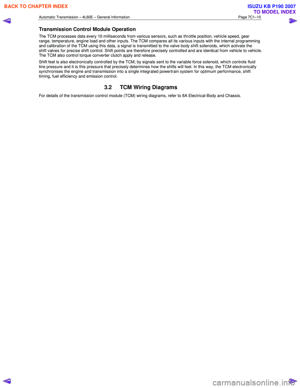
Transmission Control Module Operation
The TCM processes data every 10 milliseconds from various sensors, such as throttle position, vehicle speed, gear
range, temperature, engine load and other inputs. The TCM compares all its various inputs with the internal programming
and calibration of the TCM using this data, a signal is transmitted to the valve body shift solenoids, which activate the
shift valves for precise shift control. Shift points are therefore precisely controlled and are identical from vehicle to vehic le.
The TCM also control torque converter clutch apply and release.
Shift feel is also electronically controlled by the TCM, by signals sent to the variable force solenoid, which controls fluid
line pressure and it is this pressure that precisely determines how the shifts will feel. In this way, the TCM electronically
synchronises the engine and transmission into a single integrated powertrain system for optimum performance, shift
timing, fuel efficiency and emission control.
3.2 TCM Wiring Diagrams
For details of the transmission control module (TCM) wiring diagrams, refer to 8A Electrical-Body and Chassis.
BACK TO CHAPTER INDEX
TO MODEL INDEX
ISUZU KB P190 2007
Page 3831 of 6020
Automatic Transmission – 4L60E – Electrical Diagnosis Page 7C2–45
Diagnostic Aids
• Tech 2 displays the transmission fluid temperature in degrees. After the transmission is operating, the fluid
temperature should rise steadily to a normal operating temperature, then stabilise.
• Verify the customer's driving habits, trailer towing, etc. Trailer towing should occur in D3.
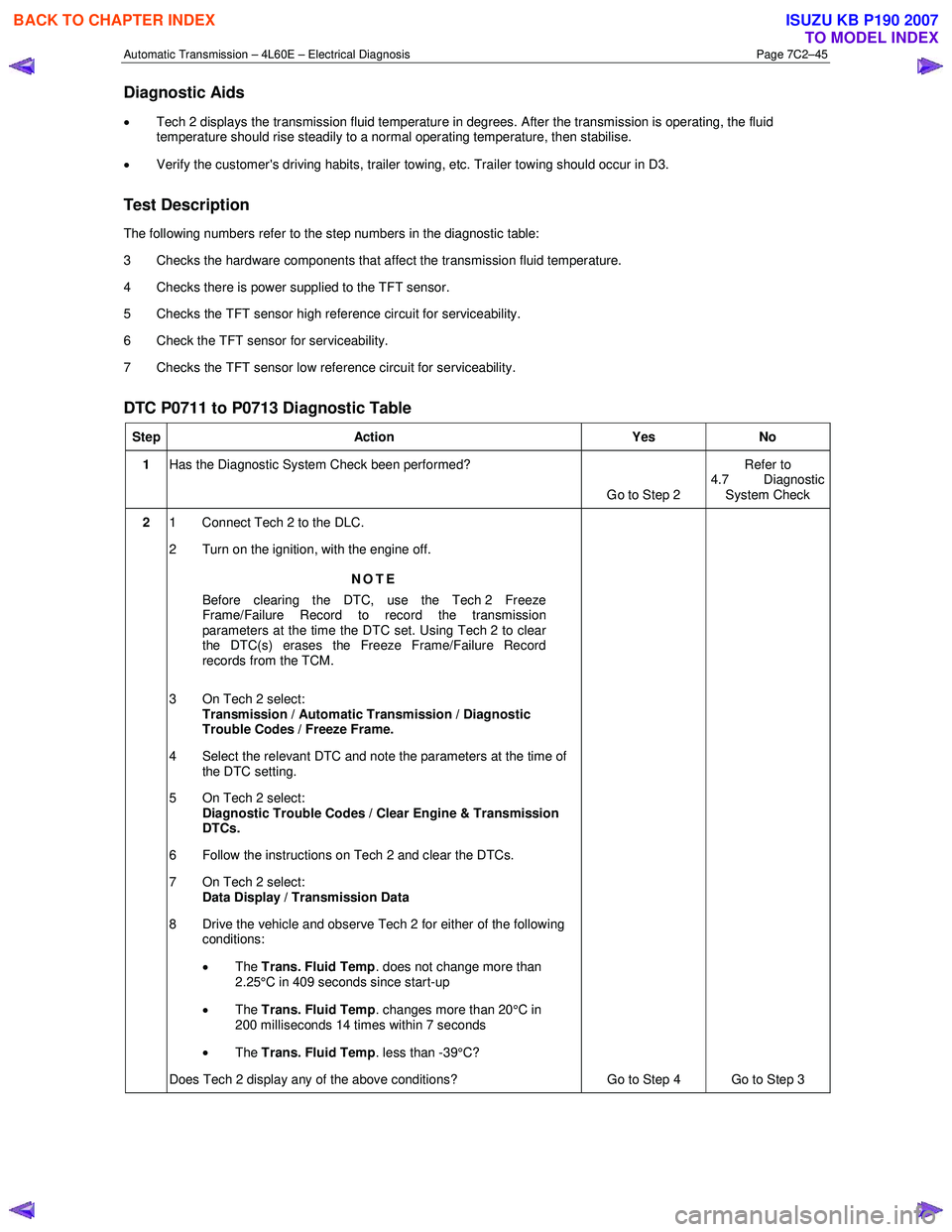
Test Description
The following numbers refer to the step numbers in the diagnostic table:
3 Checks the hardware components that affect the transmission fluid temperature.
4 Checks there is power supplied to the TFT sensor.
5 Checks the TFT sensor high reference circuit for serviceability.
6 Check the TFT sensor for serviceability.
7 Checks the TFT sensor low reference circuit for serviceability.
DTC P0711 to P0713 Diagnostic Table
Step Action Yes No
1 Has the Diagnostic System Check been performed?
Go to Step 2 Refer to
4.7 Diagnostic System Check
2 1 Connect Tech 2 to the DLC.
2 Turn on the ignition, with the engine off.
NOTE
Before clearing the DTC, use the Tech 2 Freeze
Frame/Failure Record to record the transmission
parameters at the time the DTC set. Using Tech 2 to clear
the DTC(s) erases the Freeze Frame/Failure Record
records from the TCM.
3 On Tech 2 select: Transmission / Automatic Transmission / Diagnostic
Trouble Codes / Freeze Frame.
4 Select the relevant DTC and note the parameters at the time of the DTC setting.
5 On Tech 2 select:
Diagnostic Trouble Codes / Clear Engine & Transmission
DTCs.
6 Follow the instructions on Tech 2 and clear the DTCs.
7 On Tech 2 select: Data Display / Transmission Data
8 Drive the vehicle and observe Tech 2 for either of the following conditions:
• The Trans. Fluid Temp . does not change more than
2.25°C in 409 seconds since start-up
• The Trans. Fluid Temp . changes more than 20°C in
200 milliseconds 14 times within 7 seconds
• The Trans. Fluid Temp . less than -39°C?
Does Tech 2 display any of the above conditions? Go to Step 4 Go to Step 3
BACK TO CHAPTER INDEX
TO MODEL INDEX
ISUZU KB P190 2007
Page 3836 of 6020
Automatic Transmission – 4L60E – Electrical Diagnosis Page 7C2–50
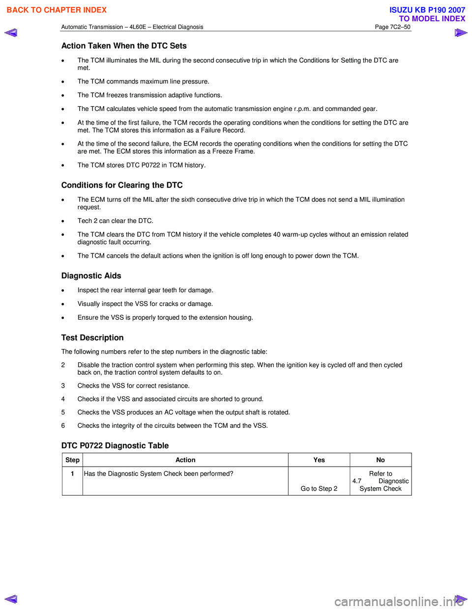
Action Taken When the DTC Sets
• The TCM illuminates the MIL during the second consecutive trip in which the Conditions for Setting the DTC are
met.
• The TCM commands maximum line pressure.
• The TCM freezes transmission adaptive functions.
• The TCM calculates vehicle speed from the automatic transmission engine r.p.m. and commanded gear.
• At the time of the first failure, the TCM records the operating conditions when the conditions for setting the DTC are
met. The TCM stores this information as a Failure Record.
• At the time of the second failure, the ECM records the operating conditions when the conditions for setting the DTC
are met. The ECM stores this information as a Freeze Frame.
• The TCM stores DTC P0722 in TCM history.
Conditions for Clearing the DTC
• The ECM turns off the MIL after the sixth consecutive drive trip in which the TCM does not send a MIL illumination
request.
• Tech 2 can clear the DTC.
• The TCM clears the DTC from TCM history if the vehicle completes 40 warm-up cycles without an emission related
diagnostic fault occurring.
• The TCM cancels the default actions when the ignition is off long enough to power down the TCM.
Diagnostic Aids
• Inspect the rear internal gear teeth for damage.
• Visually inspect the VSS for cracks or damage.
• Ensure the VSS is properly torqued to the extension housing.
Test Description
The following numbers refer to the step numbers in the diagnostic table:
2 Disable the traction control system when performing this step. W hen the ignition key is cycled off and then cycled back on, the traction control system defaults to on.
3 Checks the VSS for correct resistance.
4 Checks if the VSS and associated circuits are shorted to ground.
5 Checks the VSS produces an AC voltage when the output shaft is rotated.
6 Checks the integrity of the circuits between the TCM and the VSS.
DTC P0722 Diagnostic Table
Step Action Yes No
1 Has the Diagnostic System Check been performed?
Go to Step 2 Refer to
4.7 Diagnostic System Check
BACK TO CHAPTER INDEX
TO MODEL INDEX
ISUZU KB P190 2007
Page 3839 of 6020
Automatic Transmission – 4L60E – Electrical Diagnosis Page 7C2–53
• Ignition voltage is 8 – 18 V.
• TFT is -40°C and 150°C.
• The engine run time is greater than 5 seconds.
• The throttle position is greater than 12 percent.
• The engine torque is 108 – 882 Nm.
Conditions for Setting the DTC
The transmission output shaft speed drops greater than 1,000 r.p.m. for at least 3.4 seconds.
Action Taken When the DTC Sets
• The TCM illuminates the MIL during the second consecutive trip in which the conditions for setting the DTC are met.
• The TCM commands maximum line pressure.
• The TCM freezes transmission adaptive functions.
• The TCM calculates vehicle speed from the automatic transmission input shaft speed sensor and commanded gear.
• At the time of the first failure, the TCM records the operating conditions when the conditions for setting the DTC are
met. The TCM stores this information as a Failure Record.
• At the time of the second failure, the ECM records the operating conditions when the conditions for setting the DTC
are met. The ECM stores this information as a Freeze Frame.
• The TCM stores DTC P0723 in TCM history.
Conditions for Clearing the DTC
• The ECM turns off the MIL after the sixth consecutive drive trip in which the TCM does not send a MIL illumination
request.
• Tech 2 can clear the DTC.
• The TCM clears the DTC from TCM history if the vehicle completes 40 warm-up cycles without an emission related
diagnostic fault occurring.
• The TCM cancels the default actions when the ignition is off long enough to power down the TCM.
Diagnostic Aids
•
Inspect the rear internal gear teeth for damage.
• Visually inspect the VSS for cracks or damage.
• Ensure the VSS is properly torqued to the transmission housing.
Test Description
The following numbers refer to the step numbers in the diagnostic table:
2 Disable the traction control system when performing this step. W hen the ignition key is cycled off and then cycled back on, the traction control system defaults to on.
3 Checks the VSS for correct resistance.
4 Checks if the VSS and associated circuits are shorted to ground.
5 Checks the VSS produces an AC voltage when the output shaft is rotated.
6 Checks the integrity of the circuits between the TCM and the VSS.
BACK TO CHAPTER INDEX
TO MODEL INDEX
ISUZU KB P190 2007
Page 3908 of 6020
Automatic Transmission – 4L60E – Electrical Diagnosis Page 7C2–122
Action Taken When the DTC Sets
• The TCM requests the ECM to illuminate the MIL during the second consecutive trip in which the conditions for
setting the DTC are met.
• The TCM commands maximum line pressure.
• The TCM freezes transmission adaptive functions.
• The TCM inhibits TCC engagement.
• At the time of the first failure, the TCM records the operating conditions when the conditions for setting the DTC are
met. The TCM stores this information as a Failure Record.
• At the time of the second failure, the ECM records the operating conditions when the conditions for setting the DTC
are met. The ECM stores this information as a Freeze Frame.
• The TCM stores either DTC U0073 or DTC U0100 in TCM history during the second consecutive trip in which the
conditions for setting the DTC are met.
Conditions for Clearing the DTC
• The ECM turns off the MIL after the fourth consecutive drive trip in which the TCM does not send a MIL illumination
request.
• Tech 2 can clear the DTC.
• The TCM clears the DTC from TCM history if the vehicle completes 40 warm-up cycles without a non-emission
related diagnostic fault occurring.
• The TCM cancels the DTC default actions when the ignition is off long enough to power down the TCM.
Test Description
The following number refers to the step numbers in the diagnostic table:
1 The following tests are included in the Diagnostic System Check.
• Tests the integrity of the GM LAN serial data communication circuit.
• Tests for fault conditions on the vehicle immobiliser system stored in the ICU.
DTC P0864 and U0101 Diagnostic Table
Step Action Yes No
1 Has the Diagnostic System Check been performed?
Go to Step 2 Refer to
4.7 Diagnostic System Check
BACK TO CHAPTER INDEX
TO MODEL INDEX
ISUZU KB P190 2007
Page 3926 of 6020
Automatic Transmission – 4L60E – On-vehicle Servicing Page 7C4–13
d Install the grooved pin (13) in the selector lever.
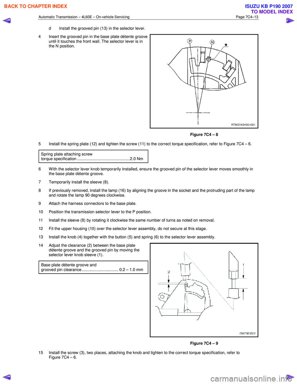
4 Insert the grooved pin in the base plate détente groove until it touches the front wall. The selector lever is in
the N position.
Figure 7C4 – 8
5 Install the spring plate (12) and tighten the screw (11) to the correct torque specification, refer to Figure 7C4 – 6.
Spring plate attaching screw
torque specification ..............................................2.0 Nm
6 W ith the selector lever knob temporarily installed, ensure the grooved pin of the selector lever moves smoothly in the base plate détente groove.
7 Temporarily install the sleeve (8).
8 If previously removed, install the lamp (16) by aligning the groove in the socket and the protruding part of the lamp and rotate the lamp 90 degrees clockwise.
9 Attach the harness connectors to the base plate.
10 Position the transmission selector lever to the P position.
11 Install the sleeve (8) by rotating it clockwise the same number of turns as noted on removal.
12 Fit the upper housing (10) over the selector lever assembly, do not secure at this stage.
13 Install the knob (4) together with the button (5) and spring (6) to the selector lever assembly.
14 Adjust the clearance (2) between the base plate détente groove and the grooved pin by moving the
selector lever knob sleeve (1).
Base plate détente groove and
grooved pin clearance................................ 0.2 – 1.0 mm
Figure 7C4 – 9
15 Install the screw (3), two places, attaching the knob and tighten to the correct torque specification, refer to Figure 7C4 – 6.
BACK TO CHAPTER INDEX
TO MODEL INDEX
ISUZU KB P190 2007
Page 4112 of 6020
ON-VEHICLE SERVICE (AW30–40LE) 7A3-27
4. Install the spring plate.
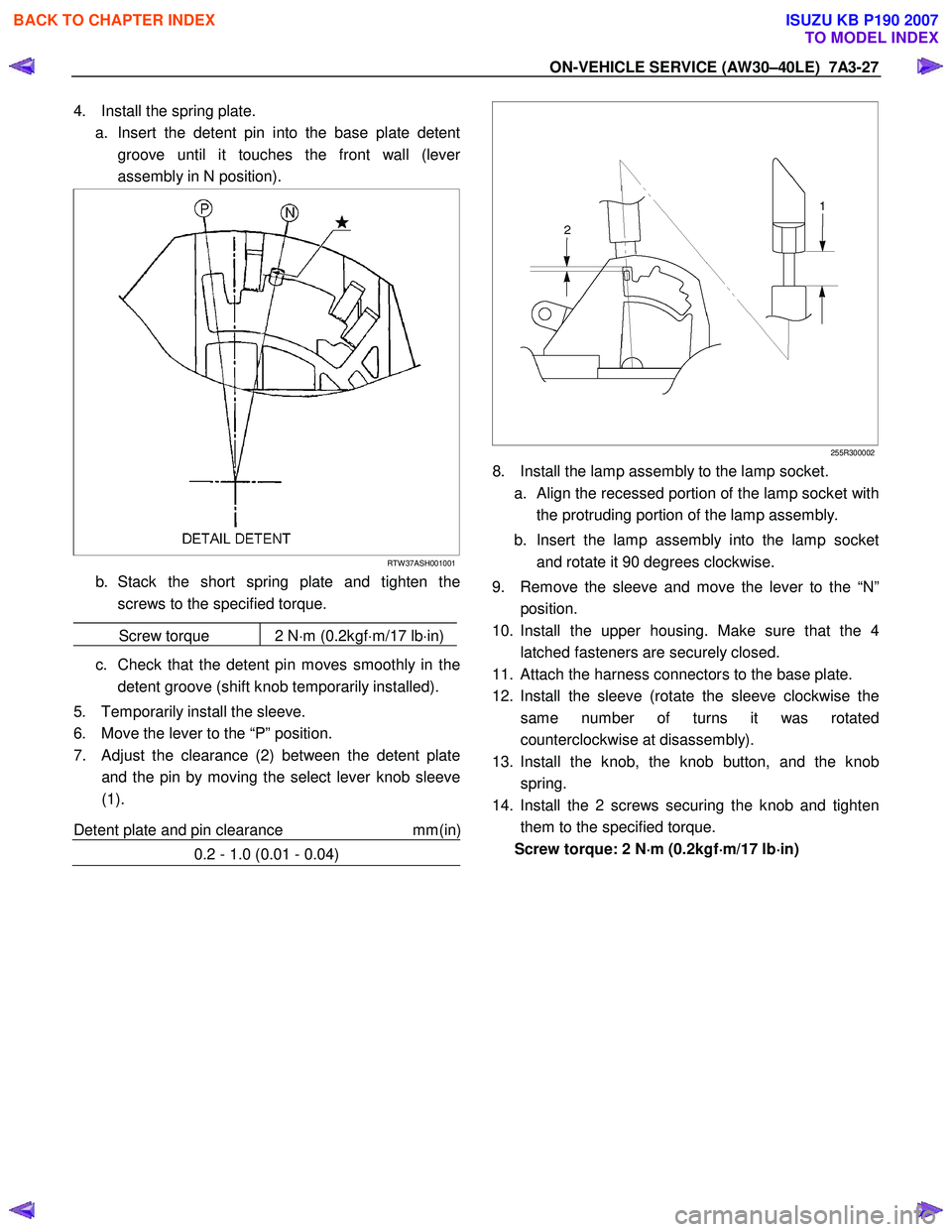
a. Insert the detent pin into the base plate detent groove until it touches the front wall (leve
r
assembly in N position).
RTW 37ASH001001
b. Stack the short spring plate and tighten thescrews to the specified torque.
Screw torque 2 N ⋅m (0.2kgf ⋅m/17 lb ⋅in)
c. Check that the detent pin moves smoothly in the
detent groove (shift knob temporarily installed).
5. Temporarily install the sleeve.
6. Move the lever to the “P” position.
7. Adjust the clearance (2) between the detent plate and the pin by moving the select lever knob sleeve
(1).
Detent plate and pin clearance mm(in
)
0.2 - 1.0 (0.01 - 0.04)
255R300002
8. Install the lamp assembly to the lamp socket.
a.
Align the recessed portion of the lamp socket with
the protruding portion of the lamp assembly.
b. Insert the lamp assembly into the lamp socket and rotate it 90 degrees clockwise.
9. Remove the sleeve and move the lever to the “N” position.
10. Install the upper housing. Make sure that the 4 latched fasteners are securely closed.
11. Attach the harness connectors to the base plate.
12. Install the sleeve (rotate the sleeve clockwise the same number of turns it was rotated
counterclockwise at disassembly).
13. Install the knob, the knob button, and the knob spring.
14. Install the 2 screws securing the knob and tighten them to the specified torque.
Screw torque: 2 N ⋅
⋅⋅
⋅
m (0.2kgf ⋅
⋅⋅
⋅
m/17 lb ⋅
⋅⋅
⋅
in)
BACK TO CHAPTER INDEX
TO MODEL INDEX
ISUZU KB P190 2007