2007 ISUZU KB P190 low beam
[x] Cancel search: low beamPage 104 of 6020

1-70 HEATER AND AIR CONDITIONING
BLOWER UNIT ASSEMBLY
REMOVAL AND INSTALLATION
This illustration is based on RHD model
RTW 710LF001801
Removal Steps
1. Control cable
2. Instrument panel assembly and cross
beam
3. Electronic thermostat connector
4. Evaporator or duct
5. Resistor connector
6. Blower motor connector
7. Blower unit assembly or intake box assembly
Installation Steps
7. Blower unit assembly or intake box
assembly
6. Blower motor connector
5. Resistor connector
4. Evaporator or duct
3. Electronic thermostat connector
2. Instrument panel assembly and cross
beam
1. Control cable
BACK TO CHAPTER INDEX
TO MODEL INDEX
ISUZU KB P190 2007
Page 772 of 6020

5D-2 PARKING BRAKE SYSTEM
Parking Brake Lever
Parking Brake Lever Assembly and Associated Parts (Bench Seat)
This illustration is based on the RHD model
RTW 75DMF000101
Legend
(1) Front Console Assembly
(2) Glove Box
(3) Instrument Panel Driver Lower Cover Assembly
(4) Driver Knee Bolster Assembly
(5) Driver Air Bag
(6) Steering W heel/Steering Cowl
(7) Meter Cluster Assembly
(8) Dash Side Trim Cover
(9) Front Pillar Trim Cover
(10) Instrument Panel Assembly & Cross Beam
BACK TO CHAPTER INDEX
TO MODEL INDEX
ISUZU KB P190 2007
Page 3651 of 6020
Battery Page 6D1-3–11
b W ait 15 seconds for the battery to recover.
8 If possible, set the selector to 50% of rapid discharge current (or three times the 20 hour discharge rate).
9 Apply the load test for 10 seconds and record the battery voltage. If one cell is faulty it will gas excessively or overheat. This indicates a faulty battery.
10 Recharge the battery if the voltage is at or below the minimum voltage specified by the HRD manufacturer (or 9.6 V).
11 Replace the battery if the voltage is below the minimum voltage specified by the HRD manufacturer (or below 9.6 V after the battery is charged and the test is repeated). Refer to 4.1 Battery.
12 Connect the battery positive terminal.
13 Connect the battery negative terminal.
Alternate Load Test
If HRD test equipment is not available, test the battery as follows:
1 Read and obey the safety precautions for working with batteries, refer to 2 Safety Precautions.
2 Ensure the state of the battery is at least 65% charged. Refer to 3.3 Hydrometer Test.
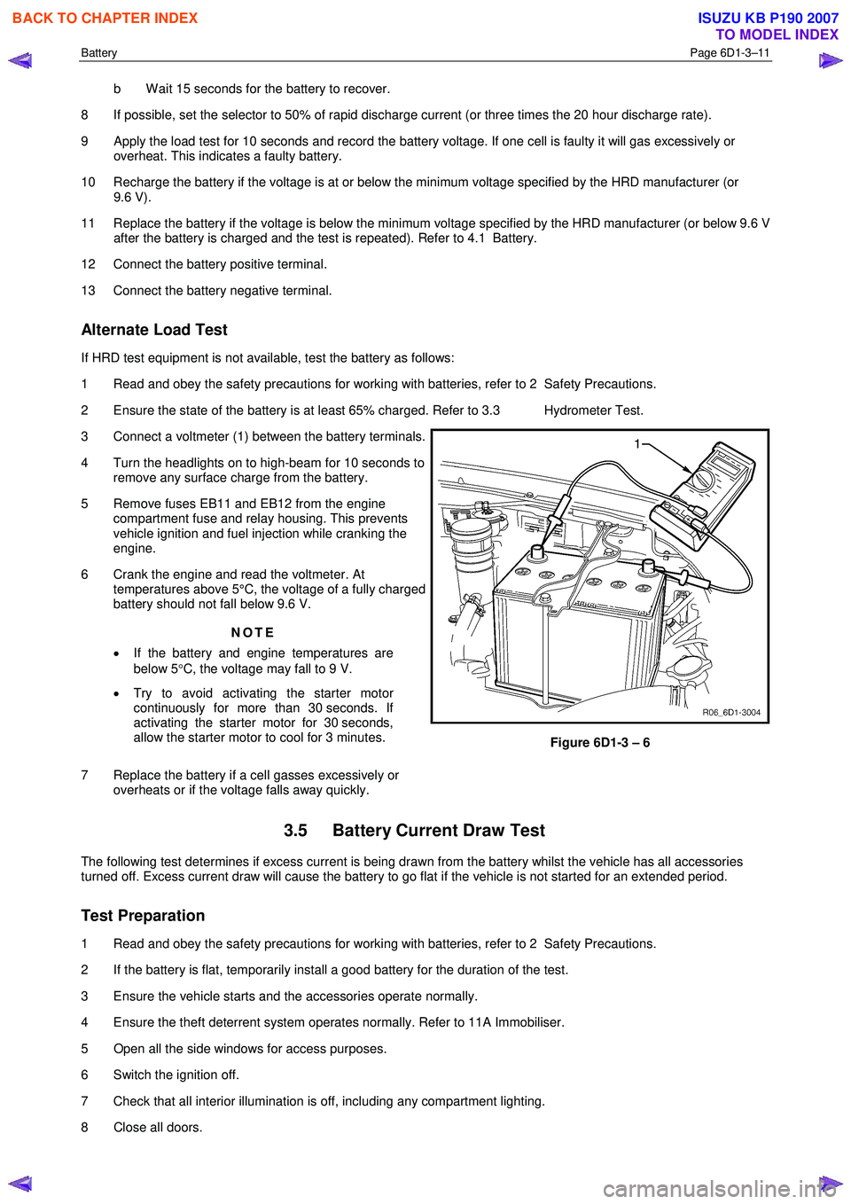
3 Connect a voltmeter (1) between the battery terminals.
4 Turn the headlights on to high-beam for 10 seconds to remove any surface charge from the battery.
5 Remove fuses EB11 and EB12 from the engine compartment fuse and relay housing. This prevents
vehicle ignition and fuel injection while cranking the
engine.
6 Crank the engine and read the voltmeter. At temperatures above 5°C, the voltage of a fully charged
battery should not fall below 9.6 V.
NOTE
• If the battery and engine temperatures are
below 5 °C, the voltage may fall to 9 V.
• Try to avoid activating the starter motor
continuously for more than 30 seconds. If
activating the starter motor for 30 seconds,
allow the starter motor to cool for 3 minutes.
7 Replace the battery if a cell gasses excessively or overheats or if the voltage falls away quickly.
Figure 6D1-3 – 6
3.5 Battery Current Draw Test
The following test determines if excess current is being drawn from the battery whilst the vehicle has all accessories
turned off. Excess current draw will cause the battery to go flat if the vehicle is not started for an extended period.
Test Preparation
1 Read and obey the safety precautions for working with batteries, refer to 2 Safety Precautions.
2 If the battery is flat, temporarily install a good battery for the duration of the test.
3 Ensure the vehicle starts and the accessories operate normally.
4 Ensure the theft deterrent system operates normally. Refer to 11A Immobiliser.
5 Open all the side windows for access purposes.
6 Switch the ignition off.
7 Check that all interior illumination is off, including any compartment lighting.
8 Close all doors.
BACK TO CHAPTER INDEX
TO MODEL INDEX
ISUZU KB P190 2007
Page 3823 of 6020
Automatic Transmission – 4L60E – Electrical Diagnosis Page 7C2–37
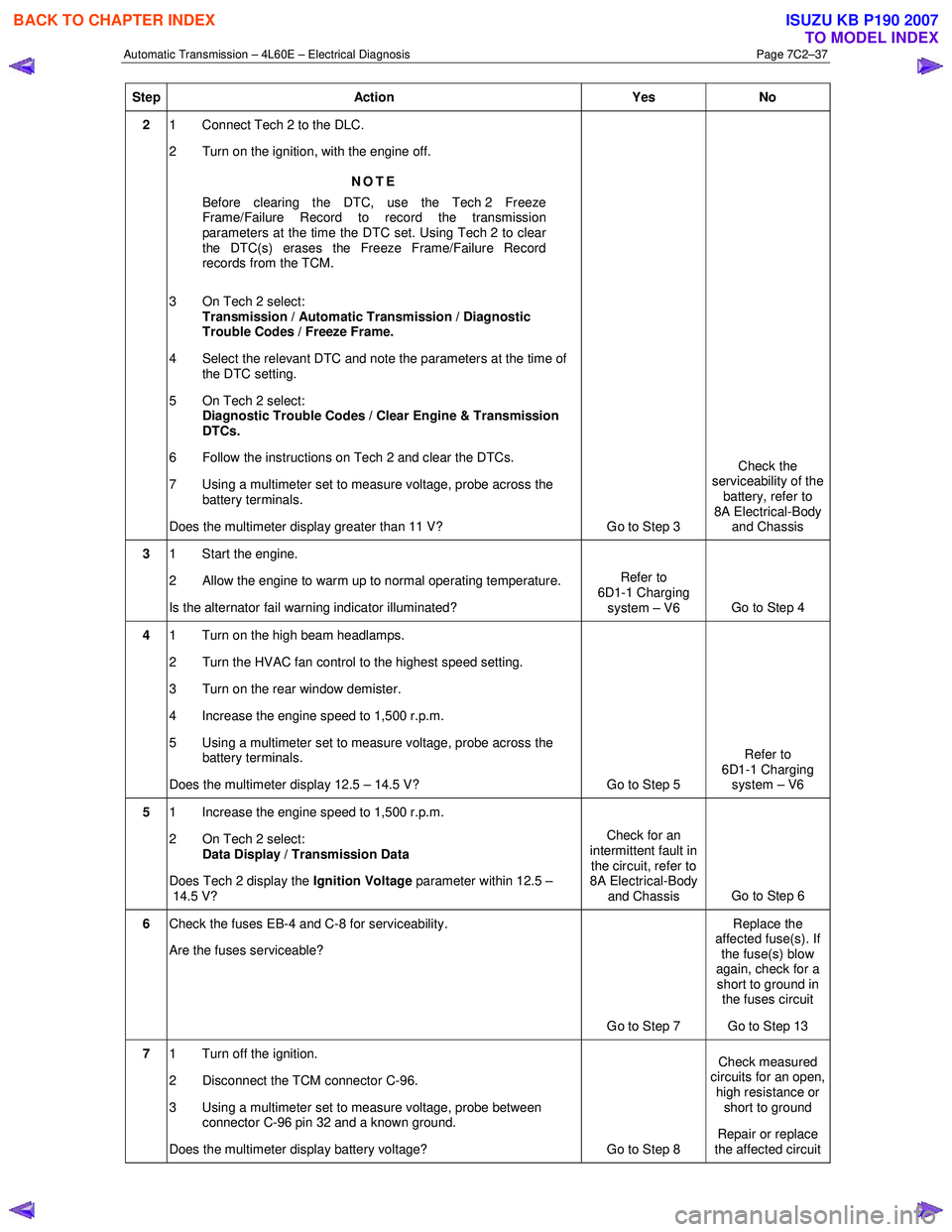
Step Action Yes No
2 1 Connect Tech 2 to the DLC.
2 Turn on the ignition, with the engine off.
NOTE
Before clearing the DTC, use the Tech 2 Freeze
Frame/Failure Record to record the transmission
parameters at the time the DTC set. Using Tech 2 to clear
the DTC(s) erases the Freeze Frame/Failure Record
records from the TCM.
3 On Tech 2 select: Transmission / Automatic Transmission / Diagnostic
Trouble Codes / Freeze Frame.
4 Select the relevant DTC and note the parameters at the time of the DTC setting.
5 On Tech 2 select:
Diagnostic Trouble Codes / Clear Engine & Transmission
DTCs.
6 Follow the instructions on Tech 2 and clear the DTCs.
7 Using a multimeter set to measure voltage, probe across the battery terminals.
Does the multimeter display greater than 11 V? Go to Step 3 Check the
serviceability of the battery, refer to
8A Electrical-Body and Chassis
3 1 Start the engine.
2 Allow the engine to warm up to normal operating temperature.
Is the alternator fail warning indicator illuminated? Refer to
6D1-1 Charging system – V6 Go to Step 4
4 1 Turn on the high beam headlamps.
2 Turn the HVAC fan control to the highest speed setting.
3 Turn on the rear window demister.
4 Increase the engine speed to 1,500 r.p.m.
5 Using a multimeter set to measure voltage, probe across the battery terminals.
Does the multimeter display 12.5 – 14.5 V? Go to Step 5 Refer to
6D1-1 Charging system – V6
5 1 Increase the engine speed to 1,500 r.p.m.
2 On Tech 2 select: Data Display / Transmission Data
Does Tech 2 display the Ignition Voltage parameter within 12.5 –
14.5 V? Check for an
intermittent fault in the circuit, refer to
8A Electrical-Body
and Chassis Go to Step 6
6
Check the fuses EB-4 and C-8 for serviceability.
Are the fuses serviceable?
Go to Step 7 Replace the
affected fuse(s). If the fuse(s) blow
again, check for a short to ground in the fuses circuit
Go to Step 13
7 1 Turn off the ignition.
2 Disconnect the TCM connector C-96.
3 Using a multimeter set to measure voltage, probe between connector C-96 pin 32 and a known ground.
Does the multimeter display battery voltage? Go to Step 8 Check measured
circuits for an open,
high resistance or short to ground
Repair or replace
the affected circuit
BACK TO CHAPTER INDEX
TO MODEL INDEX
ISUZU KB P190 2007
Page 4963 of 6020
ELECTRICAL-BODY AND CHASSIS 8A-25
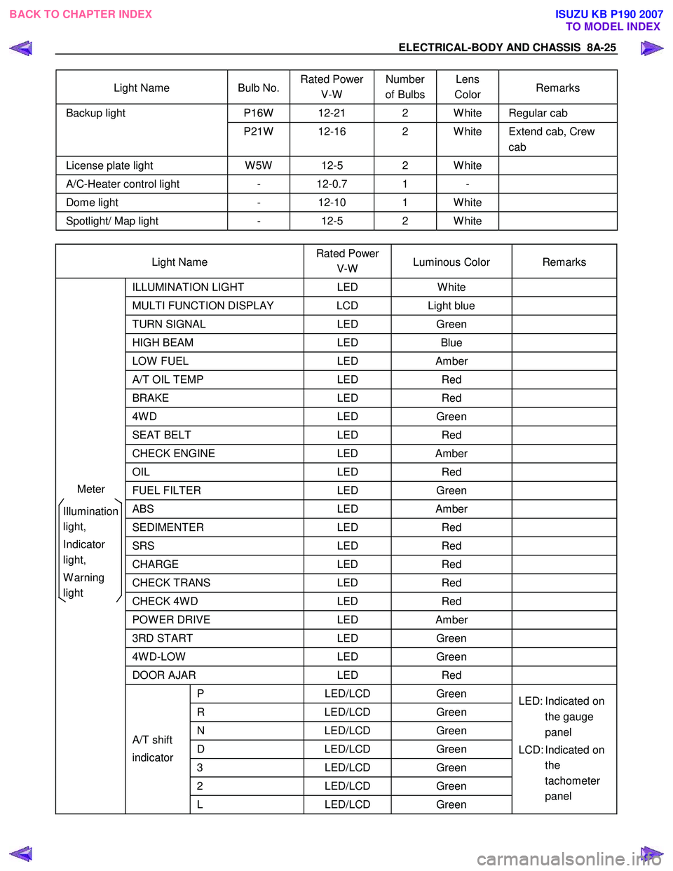
Light Name Bulb No. Rated Power
V-W Number
of Bulbs Lens
Color Remarks
P16W 12-21 2 W hite Regular cab Backup light
P21W 12-16 2 W hite Extend cab, Crew cab
License plate light W 5W 12-5 2 W hite
A/C-Heater control light - 12-0.7 1 -
Dome light - 12-10 1 W hite
Spotlight/ Map light - 12-5 2 W hite
Light Name Rated Power
V-W Luminous Color Remarks
ILLUMINATION
LIGHT LED W hite
MULTI FUNCTION DISPLAY LCD Light blue
TURN SIGNAL LED Green
HIGH BEAM LED Blue
LOW FUEL LED Amber
A/T OIL TEMP LED Red
BRAKE LED Red
4W D LED Green
SEAT BELT LED Red
CHECK ENGINE LED Amber
OIL LED Red
FUEL FILTER LED Green
ABS LED Amber
SEDIMENTER LED Red
SRS LED Red
CHARGE LED Red
CHECK TRANS LED Red
CHECK 4W D LED Red
POW ER DRIVE LED Amber
3RD START LED Green
4W D-LOW LED Green
DOOR AJAR LED Red
P LED/LCD Green
R LED/LCD Green
N LED/LCD Green
D LED/LCD Green
3 LED/LCD Green
2 LED/LCD Green
A/T shift
indicator
L LED/LCD Green LED: Indicated on
the gauge
panel
LCD: Indicated on the
tachometer
panel
Meter
Illumination
light,
Indicator
light,
W arning
light
BACK TO CHAPTER INDEX TO MODEL INDEXISUZU KB P190 2007
Page 5098 of 6020
8A-160 ELECTRICAL-BODY AND CHASSIS
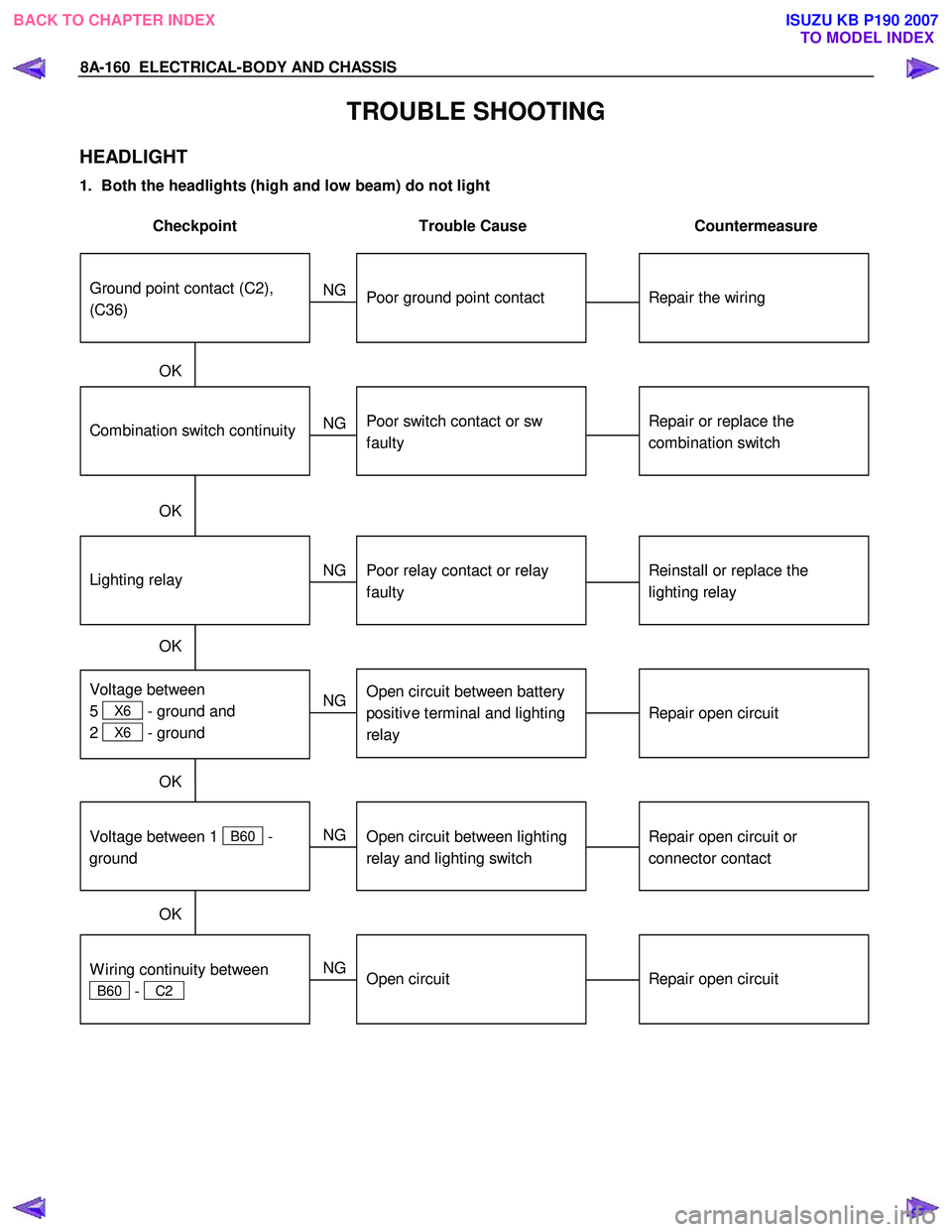
TROUBLE SHOOTING
HEADLIGHT
1. Both the headlights (high and low beam) do not light
Checkpoint Trouble Cause Countermeasure
Repair the wiring
Poor ground point contact
NG
Repair open circuit or
connector contact
Repair open circuit
Repair or replace the
combination switch
Voltage between 1
B60 -
ground
Open circuit between lighting
relay and lighting switch
Open circuit between battery
positiv e terminal and lighting
relay
Combination switch continuity
Poor switch contact or sw
faulty
Voltage between
5
X6 - ground and
2
X6 - ground
Reinstall or replace the
lighting relay
Lighting relay
Poor relay contact or relay
faulty
NG
NG
NG
NG
OK
OK
OK
OK
Ground point contact (C2),
(C36)
Repair open circuit
W iring continuity between
B60 - C2
Open circuit
NG
OK
BACK TO CHAPTER INDEX
TO MODEL INDEXISUZU KB P190 2007
Page 5099 of 6020
ELECTRICAL-BODY AND CHASSIS 8A-161
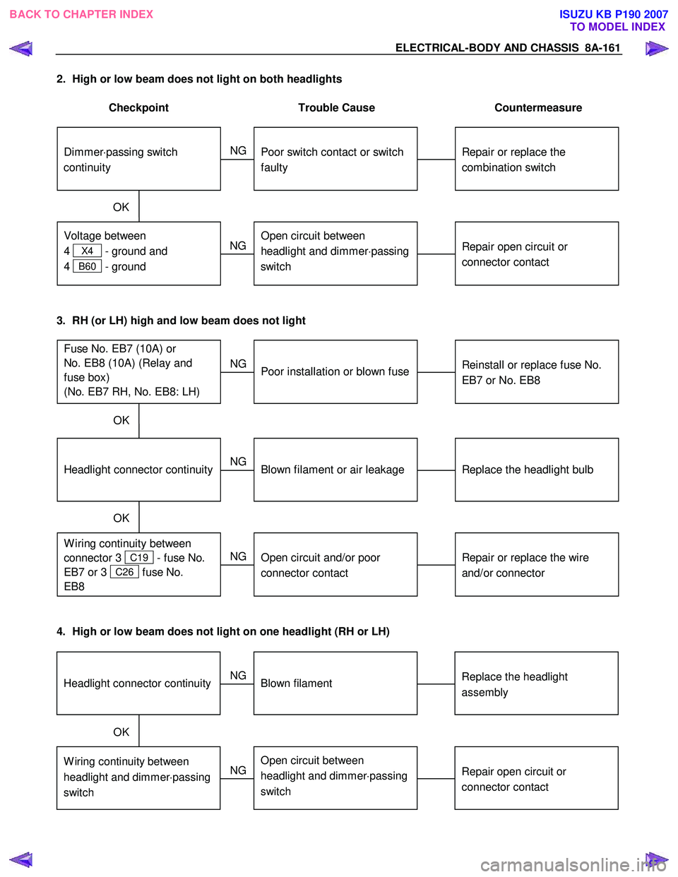
2. High or low beam does not light on both headlights
Checkpoint Trouble Cause Countermeasure
Repair or replace the
combination switch
Dimmer ⋅passing switch
continuity
Poor switch contact or switch
faulty
NG
Repair open circuit or
connector contact
Voltage between
4
X4 - ground and
4
B60 - ground
Open circuit between
headlight and dimmer ⋅passing
switch
NG
OK
3. RH (or LH) high and low beam does not light
Replace the headlight bulb
Headlight connector continuity
Blown filament or air leakage
NG
Repair or replace the wire
and/or connector
W iring continuity between
connector 3
C19 - fuse No.
EB7 or 3
C26 fuse No.
EB8
Open circuit and/or poor
connector contact
NG
OK
Reinstall or replace fuse No.
EB7 or No. EB8
Fuse No. EB7 (10A) or
No. EB8 (10A) (Relay and
fuse box)
(No. EB7 RH, No. EB8: LH)
Poor installation or blown fuse
NG
OK
4. High or low beam does not light on one headlight (RH or LH)
Replace the headlight
assemblyHeadlight connector continuityBlown filament
NG
Repair open circuit or
connector contactW iring continuity between
headlight and dimmer ⋅passing
switchOpen circuit between
headlight and dimmer ⋅passing
switch
NG
OK
BACK TO CHAPTER INDEX
TO MODEL INDEXISUZU KB P190 2007
Page 5111 of 6020
ELECTRICAL-BODY AND CHASSIS 8A-173
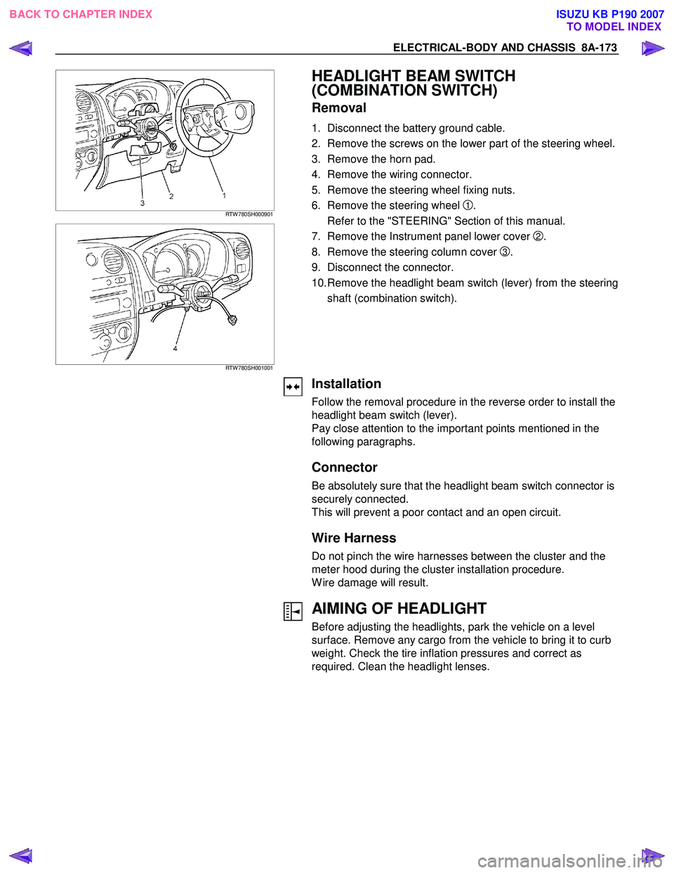
RTW 780SH000901
RTW 780SH001001
HEADLIGHT BEAM SWITCH
(COMBINATION SWITCH)
Removal
1. Disconnect the battery ground cable.
2. Remove the screws on the lower part of the steering wheel.
3. Remove the horn pad.
4. Remove the wiring connector.
5. Remove the steering wheel fixing nuts.
6. Remove the steering wheel
1.
Refer to the "STEERING" Section of this manual.
7. Remove the Instrument panel lower cover
2.
8. Remove the steering column cover
3.
9. Disconnect the connector.
10. Remove the headlight beam switch (lever) from the steering shaft (combination switch).
Installation
Follow the removal procedure in the reverse order to install the
headlight beam switch (lever).
Pay close attention to the important points mentioned in the
following paragraphs.
Connector
Be absolutely sure that the headlight beam switch connector is
securely connected.
This will prevent a poor contact and an open circuit.
Wire Harness
Do not pinch the wire harnesses between the cluster and the
meter hood during the cluster installation procedure.
W ire damage will result.
AIMING OF HEADLIGHT
Before adjusting the headlights, park the vehicle on a level
surface. Remove any cargo from the vehicle to bring it to curb
weight. Check the tire inflation pressures and correct as
required. Clean the headlight lenses.
BACK TO CHAPTER INDEX TO MODEL INDEXISUZU KB P190 2007