2007 ISUZU KB P190 EGR
[x] Cancel search: EGRPage 5560 of 6020
8A-622 ELECTRICAL-BODY AND CHASSIS
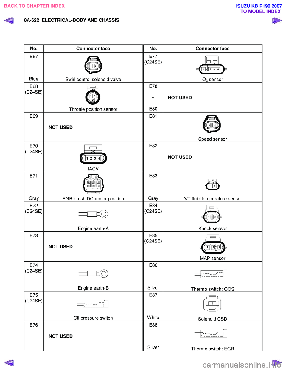
No. Connector face No. Connector face
E67
Blue
Swirl control solenoid valve E77
(C24SE)
O2 sensor
E68
(C24SE)
Throttle position sensor E78
~
E80 NOT USED
E69
NOT USED E81
Speed sensor
E70
(C24SE)
IACV E82
NOT USED
E71
Gray
EGR brush DC motor position E83
Gray A/T fluid temperature sensor
E72
(C24SE)
Engine earth-A E84
(C24SE)
Knock sensor
E73
NOT USED E85
(C24SE)
MAP sensor
E74
(C24SE)
Engine earth-B E86
SilverThermo switch; QOS
E75
(C24SE)
Oil pressure switch E87
WhiteSolenoid CSD
E76
NOT USED E88
Silver
Thermo switch; EGR
BACK TO CHAPTER INDEX TO MODEL INDEXISUZU KB P190 2007
Page 5583 of 6020
Cruise Control – HFV6 Page 8C–5
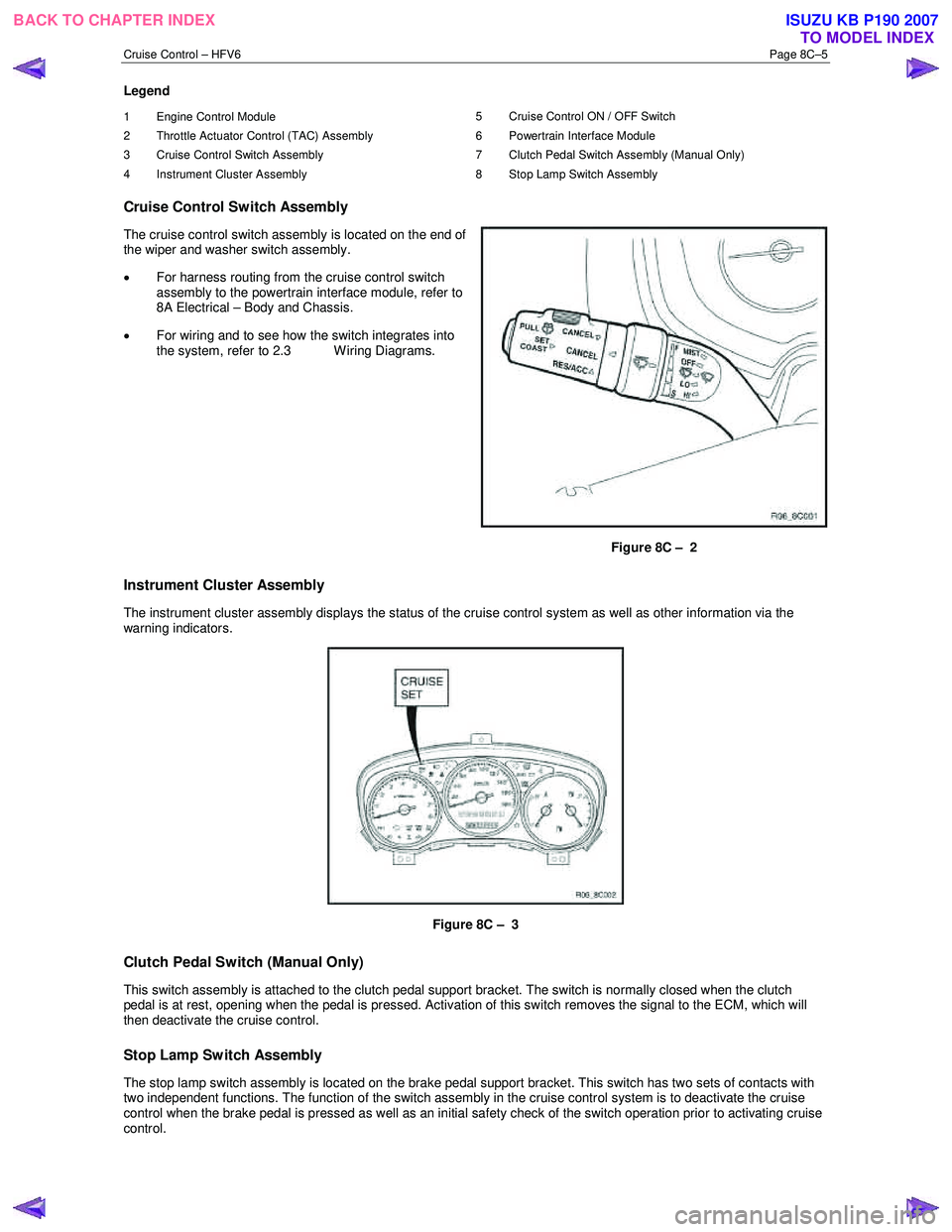
Legend
1 Engine Control Module
2 Throttle Actuator Control (TAC) Assembly
3 Cruise Control Switch Assembly
4 Instrument Cluster Assembly 5 Cruise Control ON / OFF Switch
6 Powertrain Interface Module
7 Clutch Pedal Switch Assembly (Manual Only)
8 Stop Lamp Switch Assembly
Cruise Control Switch Assembly
The cruise control switch assembly is located on the end of
the wiper and washer switch assembly.
• For harness routing from the cruise control switch
assembly to the powertrain interface module, refer to
8A Electrical – Body and Chassis.
• For wiring and to see how the switch integrates into
the system, refer to 2.3 W iring Diagrams.
Figure 8C – 2
Instrument Cluster Assembly
The instrument cluster assembly displays the status of the cruise control system as well as other information via the
warning indicators.
Figure 8C – 3
Clutch Pedal Switch (Manual Only)
This switch assembly is attached to the clutch pedal support bracket. The switch is normally closed when the clutch
pedal is at rest, opening when the pedal is pressed. Activation of this switch removes the signal to the ECM, which will
then deactivate the cruise control.
Stop Lamp Switch Assembly
The stop lamp switch assembly is located on the brake pedal support bracket. This switch has two sets of contacts with
two independent functions. The function of the switch assembly in the cruise control system is to deactivate the cruise
control when the brake pedal is pressed as well as an initial safety check of the switch operation prior to activating cruise
control.
BACK TO CHAPTER INDEX TO MODEL INDEXISUZU KB P190 2007
Page 5639 of 6020
9A-4 SUPPLEMENTAL RESTRAINT SYSTEM
Service Precaution
WARNING: THIS VEHICLE HAS A SUPPLEMENTAL
RESTRAINT SYSTEM (SRS). REFER TO THE SRS
COMPONENT AND WIRING LOCATION VIEW IN
ORDER TO DETERMINE WHETHER YOU ARE
PERFORMING A SERVICE ON, OR NEAR, THE SRS
COMPONENTS OR THE SRS WIRING. WHEN YOU
ARE PERFORMING A SERVICE ON OR NEAR THE
SRS COMPONENTS OR THE SRS WIRING, REFER
TO THE SRS SERVICE INFORMATION. FAILURE
TO FOLLOW WARNINGS COULD RESULT IN
POSSIBLE AIR BAG DEPLOYMENT, PERSONAL
INJURY, OR OTHERWISE UNNECESSARY SRS
SYSTEM REPAIRS.
CAUTION: Always use the correct fastener in the
proper location. When you replace a fastener, use
ONLY the exact part number for that application.
ISUZU/GM will call out those fasteners that require
a replacement after removal. ISUZU/GM will also
call out the fasteners that require thread lockers o
r
thread sealant. UNLESS OTHERWISE SPECIFIED,
do not use supplemental coatings (paints,
greases, or other corrosion inhibitors) on threaded
fasteners or fastener joint interfaces. Generally,
such coatings adversely affect the fastener torque
and the joint clamping force, and may damage the
fastener. When you install fasteners, use the
correct tightening sequence and specifications.
Following these instructions can help you avoid
damage to parts and systems.
General Description
CAUTION: When fasteners are removed, always
reinstall them at the same location from which
they were removed. If a fastener needs to be
replaced, use the correct part number fastener fo
r
that application. If the correct part numbe
r
fastener is not available, a fastener of equal size
and strength (or stronger) may be used.
Fasteners that are not reused, and those requiring
thread locking compound will be called out. The
correct torque value must be used when installing
fasteners that require it. If the above conditions
are not followed, parts or system damage could
result.
Restraint Devices
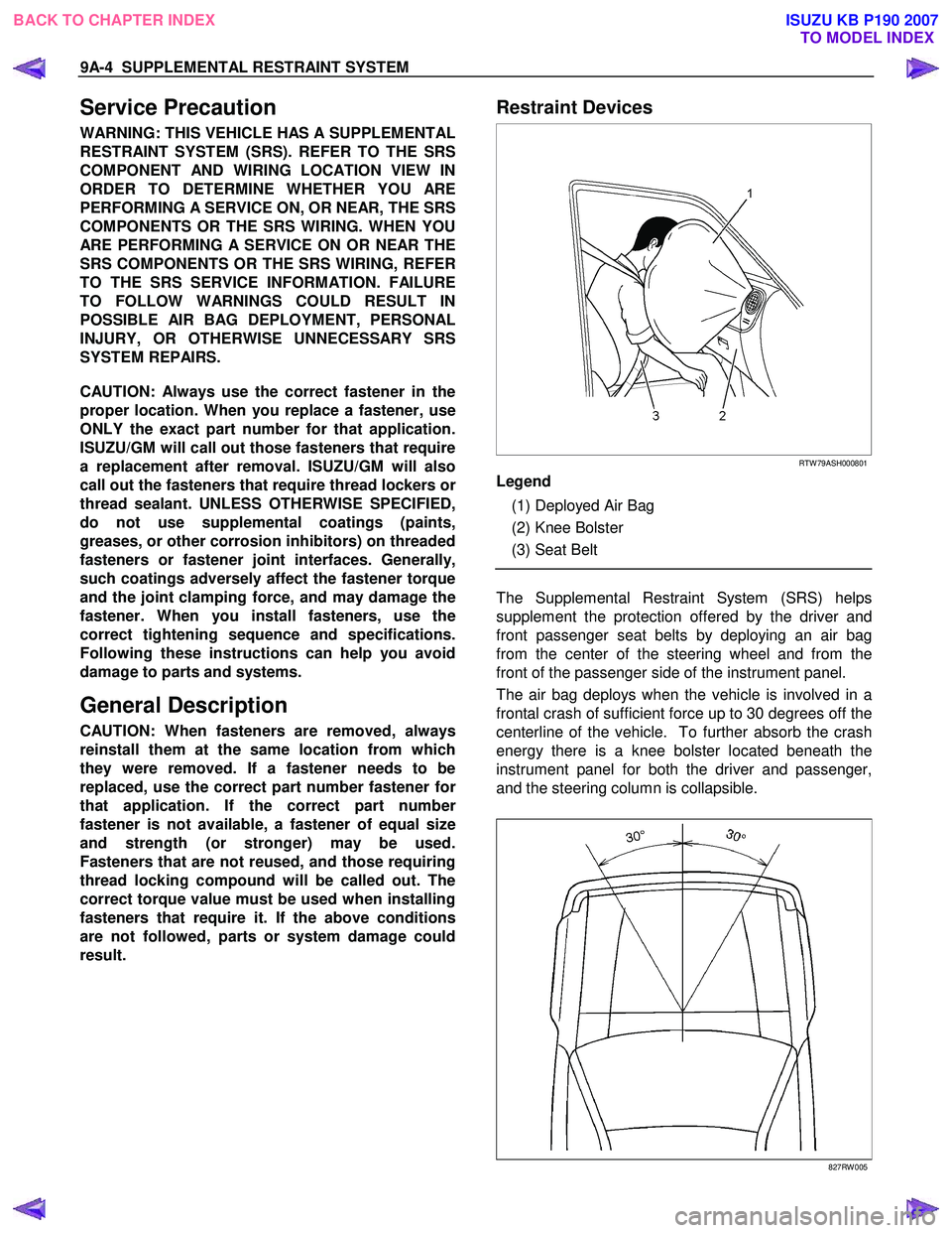
RTW 79ASH000801
Legend
(1) Deployed Air Bag
(2) Knee Bolster
(3) Seat Belt
The Supplemental Restraint System (SRS) helps
supplement the protection offered by the driver and
front passenger seat belts by deploying an air bag
from the center of the steering wheel and from the
front of the passenger side of the instrument panel.
The air bag deploys when the vehicle is involved in a
frontal crash of sufficient force up to 30 degrees off the
centerline of the vehicle. To further absorb the crash
energy there is a knee bolster located beneath the
instrument panel for both the driver and passenger,
and the steering column is collapsible.
827RW 005
BACK TO CHAPTER INDEX TO MODEL INDEXISUZU KB P190 2007
Page 5640 of 6020
SUPPLEMENTAL RESTRAINT SYSTEM 9A-5
System Description
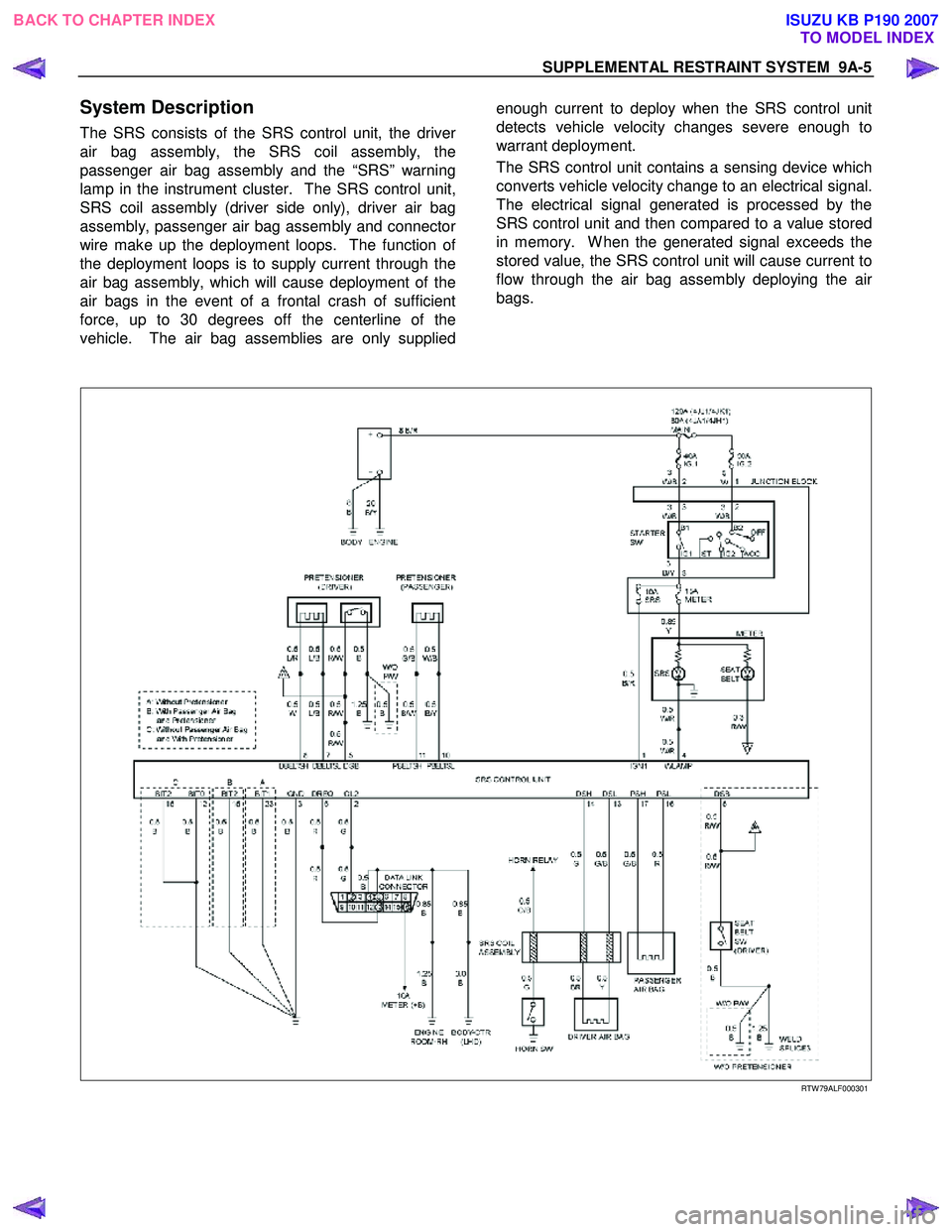
The SRS consists of the SRS control unit, the driver
air bag assembly, the SRS coil assembly, the
passenger air bag assembly and the “SRS” warning
lamp in the instrument cluster. The SRS control unit,
SRS coil assembly (driver side only), driver air bag
assembly, passenger air bag assembly and connecto
r
wire make up the deployment loops. The function of
the deployment loops is to supply current through the
air bag assembly, which will cause deployment of the
air bags in the event of a frontal crash of sufficient
force, up to 30 degrees off the centerline of the
vehicle. The air bag assemblies are only supplied
enough current to deploy when the SRS control unit
detects vehicle velocity changes severe enough to
warrant deployment.
The SRS control unit contains a sensing device which
converts vehicle velocity change to an electrical signal.
The electrical signal generated is processed by the
SRS control unit and then compared to a value stored
in memory. W hen the generated signal exceeds the
stored value, the SRS control unit will cause current to
flow through the air bag assembly deploying the ai
r
bags.
RTW 79ALF000301
BACK TO CHAPTER INDEX TO MODEL INDEXISUZU KB P190 2007
Page 5683 of 6020
RESTRAINT CONTROL SYSTEM 9A1-1
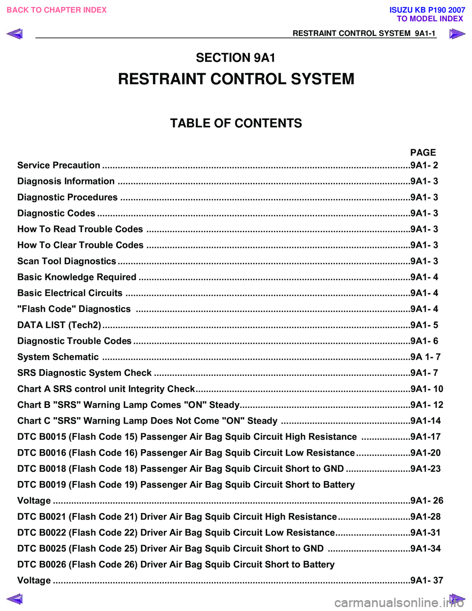
SECTION 9A1
RESTRAINT CONTROL SYSTEM
TABLE OF CONTENTS
PAGE
Service Precaution ............................................................................................................. ..........9A1- 2
Diagnosis In formation ......................................................................................................... ........9A1- 3
Diagnostic Procedures .......................................................................................................... ......9A1- 3
Diagnostic Codes ............................................................................................................... ..........9A1- 3
How To Read Trouble Codes ..................................................................................................... .9A1- 3
How To Clear Trouble Codes .................................................................................................... ..9A1- 3
Scan Tool Di agnostics .......................................................................................................... .......9A1- 3
Basic Knowledge Required ....................................................................................................... ..9A1- 4
Basic Electrical Circuits ..................................................................................................... .........9A1- 4
"Flash Code" Diagnostics ...................................................................................................... ....9A1- 4
DATA LIST (Tech2) .............................................................................................................. .........9A1- 5
Diagnostic Trouble Codes ....................................................................................................... ....9A1- 6
System Schematic .............................................................................................................. .........9A 1- 7
SRS Diagnostic System Check ...................................................................................................9 A1- 7
Chart A SRS control uni t Integrity Check...................................................................................9A1- 10
Chart B "SRS" Warning Lamp Comes "ON" Steady..................................................................9A1- 12
Chart C "SRS" Warning Lamp Does Not Come "ON" Steady ..................................................9A1-14
DTC B0015 (Flash Code 15) Passenger Air Ba g Squib Circuit High Resistance ...................9A1-17
DTC B0016 (Flash Code 16) Passenger Air Ba g Squib Circuit Low Resistance .....................9A1-20
DTC B0018 (Flash Code 18) Passenger Air Ba g Squib Circuit Short to GND.........................9A1-23
DTC B0019 (Flash Code 19) Passenger Air Bag Squib Circuit Short to Battery
Voltage ........................................................................................................................ ..................9A1- 26
DTC B0021 (Flash Code 21) Driver Air Ba g Squib Circuit High Resistance ............................9A1-28
DTC B0022 (Flash Code 22) Driver Air Ba g Squib Circuit Low Resistance.............................9A1-31
DTC B0025 (Flash Code 25) Driver Air Ba g Squib Circuit Short to GND ................................9A1-34
DTC B0026 (Flash Code 26) Driver Air Bag Squib Circuit Short to Battery
Voltage ........................................................................................................................ ..................9A1- 37
BACK TO CHAPTER INDEX
TO MODEL INDEX
ISUZU KB P190 2007
Page 5692 of 6020
9A1-10 RESTRAINT CONTROL SYSTEM
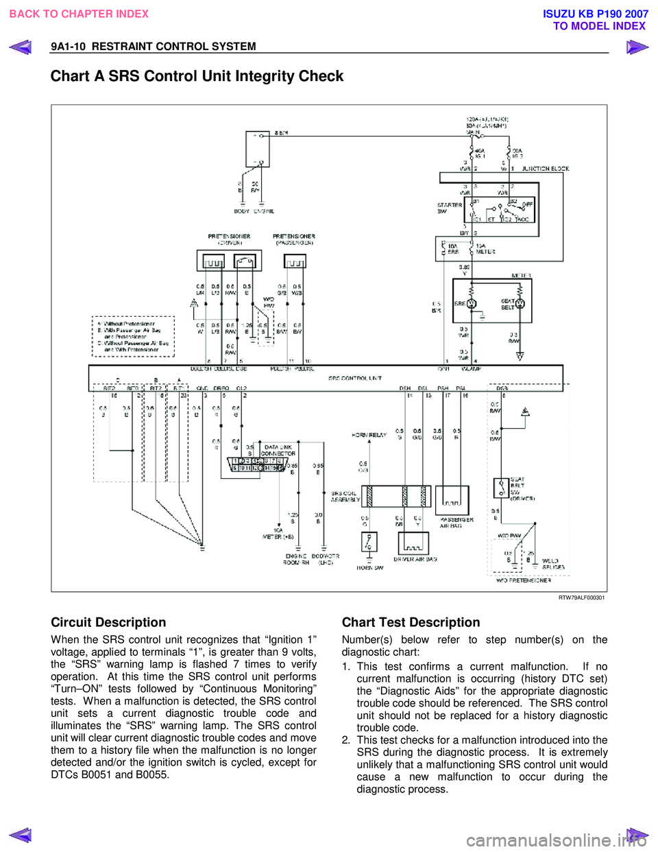
Chart A SRS Control Unit Integrity Check
RTW 79ALF000301
Circuit Description
W hen the SRS control unit recognizes that “Ignition 1”
voltage, applied to terminals “1”, is greater than 9 volts,
the “SRS” warning lamp is flashed 7 times to verif
y
operation. At this time the SRS control unit performs
“Turn–ON” tests followed by “Continuous Monitoring”
tests. W hen a malfunction is detected, the SRS control
unit sets a current diagnostic trouble code and
illuminates the “SRS” warning lamp. The SRS control
unit will clear current diagnostic trouble codes and move
them to a history file when the malfunction is no longe
r
detected and/or the ignition switch is cycled, except for
DTCs B0051 and B0055.
Chart Test Description
Number(s) below refer to step number(s) on the
diagnostic chart:
1. This test confirms a current malfunction. If no current malfunction is occurring (history DTC set)
the “Diagnostic Aids” for the appropriate diagnostic
trouble code should be referenced. The SRS control
unit should not be replaced for a history diagnostic
trouble code.
2. This test checks for a malfunction introduced into the SRS during the diagnostic process. It is extremel
y
unlikely that a malfunctioning SRS control unit would
cause a new malfunction to occur during the
diagnostic process.
BACK TO CHAPTER INDEX TO MODEL INDEX
ISUZU KB P190 2007
Page 5693 of 6020
RESTRAINT CONTROL SYSTEM 9A1-11
3. W hen all circuitry outside the SRS control unit has been found to operate properly, as indicated by the
appropriate diagnostic chart, then and only then
should the SRS control unit be replaced.
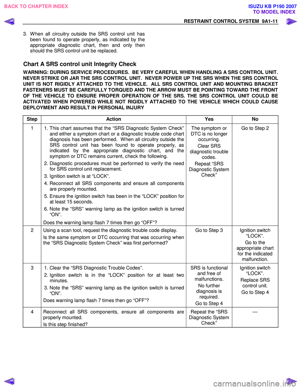
Chart A SRS control unit Integrity Check
WARNING: DURING SERVICE PROCEDURES. BE VERY CAREFUL WHEN HANDLING A SRS CONTROL UNIT.
NEVER STRIKE OR JAR THE SRS CONTROL UNIT. NEVER POWER UP THE SRS WHEN THE SRS CONTROL
UNIT IS NOT RIGIDLY ATTACHED TO THE VEHICLE. ALL SRS CONTROL UNIT AND MOUNTING BRACKET
FASTENERS MUST BE CAREFULLY TORQUED AND THE ARROW MUST BE POINTING TOWARD THE FRONT
OF THE VEHICLE TO ENSURE PROPER OPERATION OF THE SRS. THE SRS CONTROL UNIT COULD BE
ACTIVATED WHEN POWERED WHILE NOT RIGIDLY ATTACHED TO THE VEHICLE WHICH COULD CAUSE
DEPLOYMENT AND RESULT IN PERSONAL INJURY
Step Action Yes No
1 1. This chart assumes that the “SRS Diagnostic System Check”
and either a symptom chart or a diagnostic trouble code chart
diagnosis has been performed. W hen all circuitry outside the
SRS control unit has been found to operate properly, as
indicated by the appropriate diagnostic chart, and the
symptom or DTC remains current, check the following.
2. Diagnostic procedures must be performed to verify the need
for SRS control unit replacement.
3. Ignition switch is at “LOCK”.
4. Reconnect all SRS components and ensure all components are properly mounted.
5. Ensure the ignition switch has been in the “LOCK” position for
at least 15 seconds.
6. Note the “SRS” warning lamp as the ignition switch is turned
“ON”.
Does the warning lamp flash 7 times then go “OFF”? The symptom or
DTC is no longer occurring.
Clear SRS
diagnostic trouble codes.
Repeat “SRS
Diagnostic System Check” Go to Step 2
2 Using a scan tool, request the diagnostic trouble code display.
Is the same symptom or DTC occurring that was occurring when
the “SRS Diagnostic System Check” was first performed? Go to Step 3 Ignition switch
“LOCK”.
Go to the
appropriate chart for the indicated malfunction.
3 1. Clear the “SRS Diagnostic Trouble Codes”.
2. Ignition switch is in the “LOCK” position for at least two
minutes.
3. Note the “SRS” warning lamp as the ignition switch is turned
“ON”.
Does warning lamp flash 7 times then go “OFF”? SRS is functional
and free of
malfunctions.
No further
diagnosis is required.
Go to Step 4 Ignition switch
“LOCK”.
Replace SRS control unit.
Go to Step 4
4 Reconnect all SRS components, ensure all components are properly mounted.
Is this step finished? Repeat the “SRS
Diagnostic System Check” —
BACK TO CHAPTER INDEX
TO MODEL INDEX
ISUZU KB P190 2007
Page 5744 of 6020
9A1-62 RESTRAINT CONTROL SYSTEM
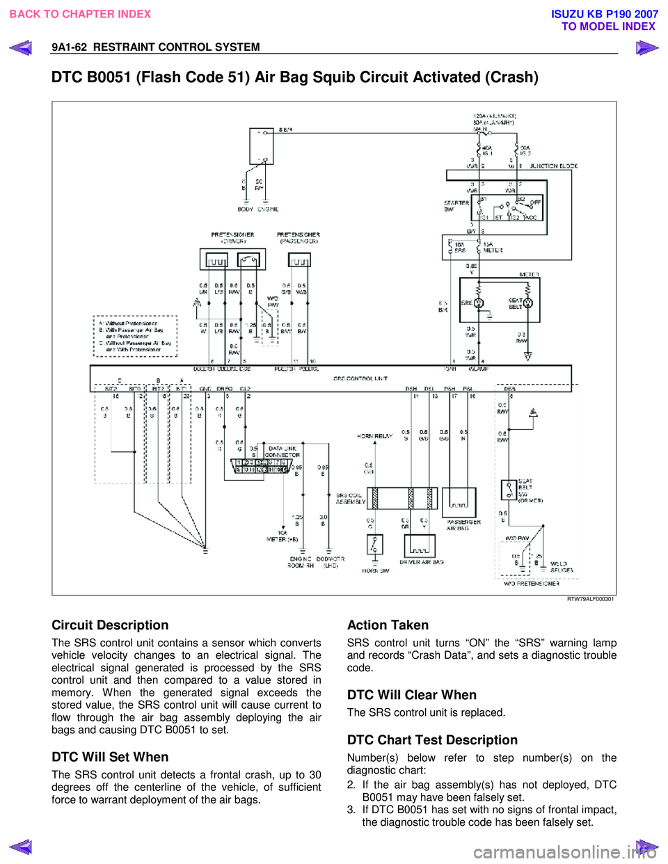
DTC B0051 (Flash Code 51) Air Bag Squib Circuit Activated (Crash)
RTW 79ALF000301
Circuit Description
The SRS control unit contains a sensor which converts
vehicle velocity changes to an electrical signal. The
electrical signal generated is processed by the SRS
control unit and then compared to a value stored in
memory. W hen the generated signal exceeds the
stored value, the SRS control unit will cause current to
flow through the air bag assembly deploying the ai
r
bags and causing DTC B0051 to set.
DTC Will Set When
The SRS control unit detects a frontal crash, up to 30
degrees off the centerline of the vehicle, of sufficient
force to warrant deployment of the air bags.
Action Taken
SRS control unit turns “ON” the “SRS” warning lamp
and records “Crash Data”, and sets a diagnostic trouble
code.
DTC Will Clear When
The SRS control unit is replaced.
DTC Chart Test Description
Number(s) below refer to step number(s) on the
diagnostic chart:
2. If the air bag assembly(s) has not deployed, DTC
B0051 may have been falsely set.
3. If DTC B0051 has set with no signs of frontal impact,
the diagnostic trouble code has been falsely set.
BACK TO CHAPTER INDEX
TO MODEL INDEX
ISUZU KB P190 2007