Page 4256 of 6020

CONSTRUCTION AND FUNCTION 7A1-17
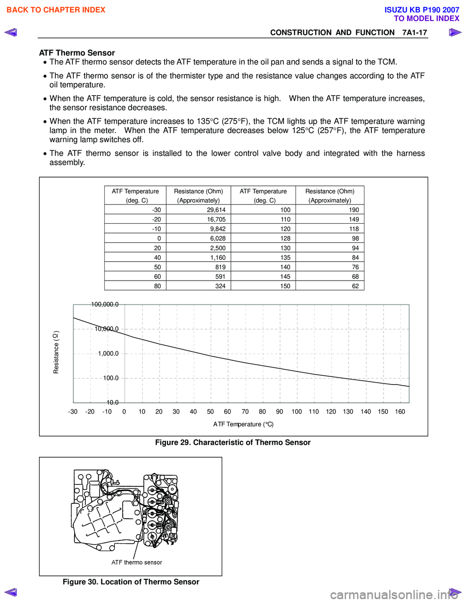
ATF Thermo Sensor • The ATF thermo sensor detects the ATF temperature in the oil pan and sends a signal to the TCM.
• The ATF thermo sensor is of the thermister type and the resistance value changes according to the ATF
oil temperature.
• When the ATF temperature is cold, the sensor resistance is high. When the ATF temperature increases,
the sensor resistance decreases.
• When the ATF temperature increases to 135 °C (275 °F), the TCM lights up the ATF temperature warning
lamp in the meter. When the ATF temperature decreases below 125 °C (257 °F), the ATF temperature
warning lamp switches off.
• The ATF thermo sensor is installed to the lower control valve body and integrated with the harness
assembly.
10.0
100.0
1,000.0
10,000.0
100,000.0
-30 -20 -10 0 10 20 30 40 50 60 70 80 90 100 110 120 130 140 150 160 A TF Temp er a t ur e ( °C)
Resistance (Ω
)
Figure 29. Characteristic of Thermo Sensor
Figure 30. Location of Thermo Sensor
ATF Temperature
(deg. C) Resistance (Ohm)
(Approximately) ATF Temperature
(deg. C) Resistance (Ohm)
(Approximately)
-30 29,614 100190
-20 16,705 110149
-10 9,842 120118
0 6,028 128 98
20 2,500 130 94
40 1,160 135 84
50 819 140 76
60 591 14568
80 324 15062
BACK TO CHAPTER INDEX
TO MODEL INDEX
ISUZU KB P190 2007
Page 4466 of 6020

7A3-12 ON-VEHICLE SERVICE (JR405E)
4. Install the spring plate.
a. Insert the detent pin into the base plate detent groove until it touches the front wall (leve
r
assembly in N position).
RTW 37ASH001001
b. Stack the short spring plate and tighten thescrews to the specified torque.
Screw torque 2 N ⋅m (0.2kgf ⋅m/17 lb ⋅in)
c. Check that the detent pin moves smoothly in the
detent groove (shift knob temporarily installed).
5. Temporarily install the sleeve.
6. Move the lever to the “P” position.
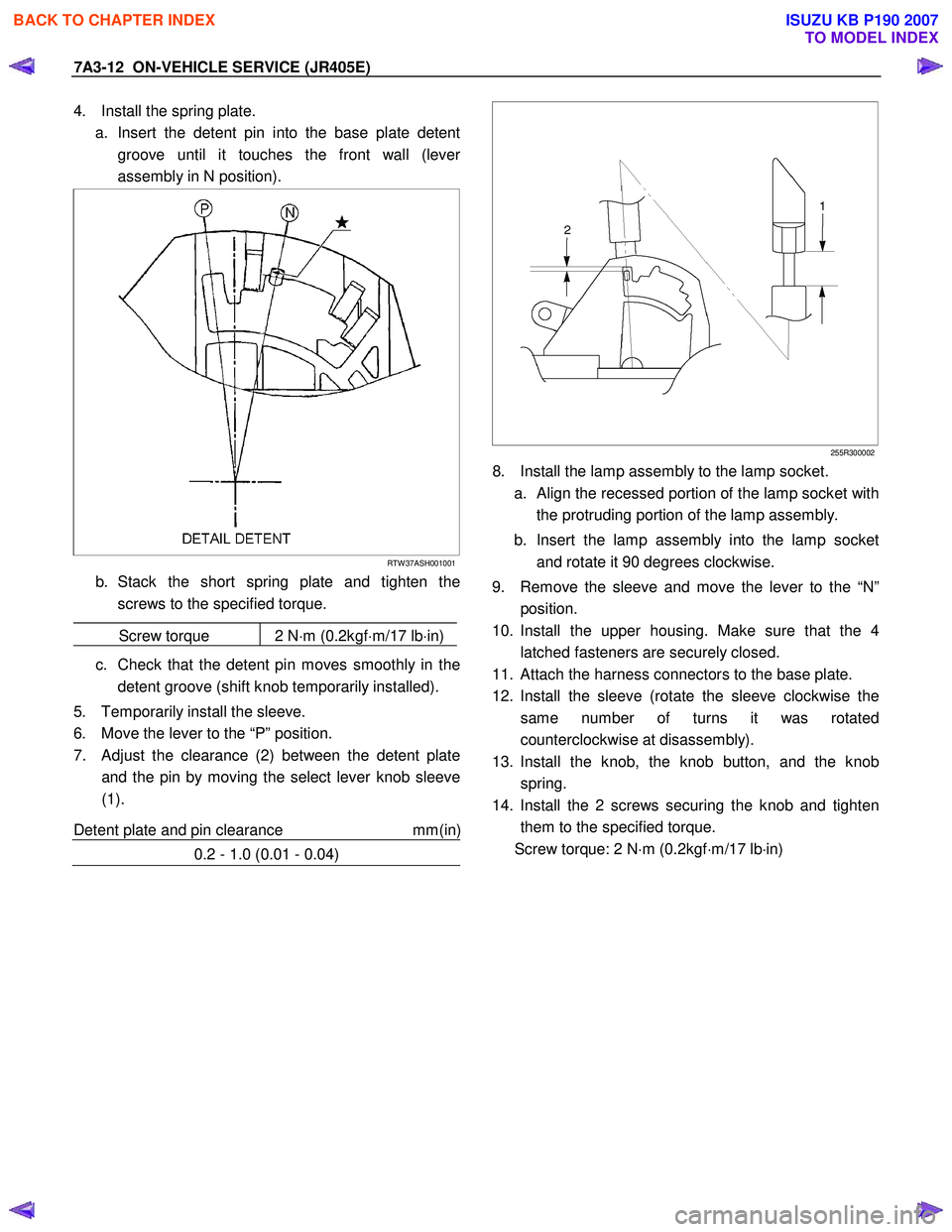
7. Adjust the clearance (2) between the detent plate and the pin by moving the select lever knob sleeve
(1).
Detent plate and pin clearance mm(in
)
0.2 - 1.0 (0.01 - 0.04)
255R300002
8. Install the lamp assembly to the lamp socket.
a.
Align the recessed portion of the lamp socket with
the protruding portion of the lamp assembly.
b. Insert the lamp assembly into the lamp socket and rotate it 90 degrees clockwise.
9. Remove the sleeve and move the lever to the “N” position.
10. Install the upper housing. Make sure that the 4 latched fasteners are securely closed.
11. Attach the harness connectors to the base plate.
12. Install the sleeve (rotate the sleeve clockwise the same number of turns it was rotated
counterclockwise at disassembly).
13. Install the knob, the knob button, and the knob spring.
14. Install the 2 screws securing the knob and tighten them to the specified torque.
Screw torque: 2 N ⋅m (0.2kgf ⋅m/17 lb ⋅in)
BACK TO CHAPTER INDEX
TO MODEL INDEX
ISUZU KB P190 2007
Page 4567 of 6020
MSG MODEL 7B-3
GENERAL DESCRIPTION
The MSG type transmission is fully synchronized 5-speed unit with blocking ring type synchronizers and a constant
mesh type reverse gear.
The unit consists principally of a case with an integral clutch housing, intermediate plate, rear cover and gears.
The top of the rear cover is a quadrant box containing the transmission control mechanism.
The case and rear cover are cast aluminum alloy to reduce weight.
BACK TO CHAPTER INDEX
TO MODEL INDEX
ISUZU KB P190 2007
Page 4610 of 6020
7B1-4 MANUAL TRANSMISSION
General Description
MUA5G/5H/5S Transmission (4×
××
×
2)
A07R300006
The MUA5G/5H/5S is a constant mesh transmission,
synchronized in all speeds. The transmission has been
designed to provide low shift effort and low gear noise.
Principle parts of the transmission are the integral clutch
housing, the intermediate plate, the rear cover, and the
gears.
The transmission control box is built into the
transmission.
BACK TO CHAPTER INDEX
TO MODEL INDEX
ISUZU KB P190 2007
Page 4659 of 6020
MANUAL TRANSMISSION 7B1-53
2. HARD SHIFTING
Checkpoint Trouble Cause Countermeasure
Change lever play
Clutch pedal free play
Repair or replace the
applicable parts and regrease
Readjust the clutch pedal free
play
W orn change lever sliding
portions
Improper clutch pedal free
play
Change lever operationRepair or regrease the change
lever assembly
Replenish or replace the
engine oil
Hard operating change lever
caused insufficient grease
Insufficient or improper gear
oil
OK
OK NG
NG
NG
NG
OK
OKGear oil
Continued on the next page
Shift rod and quadrant box
sliding faces, and other partsReplace the shidt rod and/or
the quadrant boxW orn shift rod and/or sliding
faces
Repair or replace the sleeveSleeve movement failure
NG
NG
OKShift block sleeve movement
BACK TO CHAPTER INDEX
TO MODEL INDEX
ISUZU KB P190 2007
Page 4666 of 6020
7B1-60 MANUAL TRANSMISSION
General Description
MUA5G/5H/5S Transmission (4×
××
×
4)
A07R300003
The MUA5G/5H/5S is a constant mesh transmission,
synchronized in all speeds. The transmission is
designed for a great reduction of the shift effort and the
quietest possible operation.
Principle parts of the transmission are the integral clutch
housing, the intermediate plate, the rear case, and the
gears.
The transmission control box is built into the
transmission.
BACK TO CHAPTER INDEX
TO MODEL INDEX
ISUZU KB P190 2007
Page 4713 of 6020
MANUAL TRANSMISSION 7B1-107
2. HARD SHIFTING
Checkpoint Trouble Cause Countermeasure
Change lever play
Clutch pedal free play
Repair or replace the
applicable parts and regrease
Readjust the clutch pedal free
play
W orn change lever sliding
portions
Improper clutch pedal free
play
Change lever operationRepair or regrease the change
lever assembly
Replenish or replace the
engine oil
Hard operating change lever
caused insufficient grease
Insufficient or improper gear
oil
OK
OK NG
NG
NG
NG
OK
OKGear oil
Continued on the next page
Shift rod and quadrant box
sliding faces, and other partsReplace the shidt rod and/or
the quadrant boxW orn shift rod and/or sliding
faces
Repair or replace the sleeveSleeve movement failure
NG
NG
OKShift block sleeve movement
BACK TO CHAPTER INDEX
TO MODEL INDEX
ISUZU KB P190 2007
Page 4723 of 6020

7B1-4 Manual Transmission (MUX)
Troubleshooting
ConditionPossible Cause Correction
Abnormal Noise (Noisy in Neutral) Insufficient or improper lubricant Replenish or replace lubricant Flywheel pilot bearing worn or
broken Replace flywheel pilot bearing
Bearing(s) worn or broken (Input
shaft, counter shaft, and output
shaft) Replace bearing(s)
Gear tooth contact surfaces worn or
scuffed (Input shaft, counter shaft,
output shaft, and reverse idler gear) Replace gear(s)
Spline worn (Input shaft, output
shaft, counter shaft, and
synchronizer clutch hub) Replace worn parts
Transmission misalignment Realign transmission
Abnormal Noise (Noisy Operation) Insufficient or improper lubricant (Metallic rattling) Replenish or replace lubricant
Bearing(s) worn or broken (Hissing,
thumping, or bumping) Replace bearing(s)
Gear(s) worn, chipped, or cracked
(Growling, humming, or grinding) Replace gear(s)
Gears seizing on thrust face or
inner face free running (Squealing
at high speeds) Replace gear(s)
Gears lack of backlash between
meshing (Gear whining) Replace gear(s)
Hard Shifting Insufficient or improper lubricant Replenish or replace lubricant
Improper clutch pedal free play Readjust clutch pedal free play
Hard operating of change lever
caused insufficient grease Repair or regrease change lever
assembly
Change lever sliding portions worn Repair or replace applicable parts and regrease
Shift block sleeve movement failure Repair or replace sleeve
Shift rod and/or quadrant box
sliding face worn Replace worn parts
Shift arm and/or synchronizer
sleeve groove worn Replace worn parts
Collar, and/or gear thrust faces
worn (Input shaft and counter shaft
thrust play) Replace worn parts
Synchronizer parts worn Replace worn parts
BACK TO CHAPTER INDEX
TO MODEL INDEX
ISUZU KB P190 2007