2007 ISUZU KB P190 remote control
[x] Cancel search: remote controlPage 1037 of 6020
Engine Control System (4JH1) 6E-3
Rough, Unstable, or In co rr ect Idle And
Stallin g........................................................... .6E -260
Cut Out, Mi sses.............................................. .6E -262
Su rge s/Chuggle s............................................ .6E -263
La ck of Po wer, Sluggi shne ss, Spongine ss .... .6E -266
He sitation, Sag, Stu mble................................ .6E -268
Fuel Kno ck /Co mbu stion Noi se ....................... .6E -270
Poor F uel E cono my........................................ .6E -271
E xc ess ive S moke (B la ck S m oke) ................. .6E -272
E xc ess ive S moke (W hite S moke) ................. .6E -273
Repair In str u ctions ............................................ .6E -275
Engine Control Module (ECM) Replacement ..6E-275
Service Programming System (SPS)
Description .....................................................6E-276
Service Programming System (SPS)
(Remote Procedure) ......................................6E-277
Service Programming System (SPS)
(Pass-Thru Procedure) ..................................6E-278
Accelerator Pedal Position (APP) Sensor
Replacement ..................................................6E-279
Crankshaft Position Sensor (CKP) Sensor
Replacement ..................................................6E-279
EGR Solenoid Valve Replacement .................6E-280
Engine Coolant Temperature Coolant
(ECT) Sensor Replacement ...........................6E-280
Mass Air Flow (MAF) / Intake Air Temperature
Sensor Replacement......................................6E-280
Turbocharger Solenoid Valve Replacement
[High Altitude Spec] ........................................6E-281
Vacuum Pressure Sensor Replacement
[High Altitude Spec] ........................................6E-281
Vehicle Speed Sensor (VSS) Replacement ....6E-282
Description And Operation .................................6E-283 Engine Control Module (ECM) .......................6E-283
Engine Control Component Description ..........6E-284
Fuel Injection System Description ...................6E-288
Low Pressure Fuel Circuit Description ............6E-290
High Pressure Fuel Circuit Description ...........6E-291
Timing Control Device Description ..................6E-294
Exhaust Gas Recirculation (EGR) System
Description .....................................................6E-297
Turbocharger Description................................6E-298
Special Tools And Equipment ............................6E-299 Special Tools and Equipment .........................6E-299
BACK TO CHAPTER INDEX
TO MODEL INDEX
ISUZU KB P190 2007
Page 1292 of 6020
6E-258 Engine Control System (4JH1)
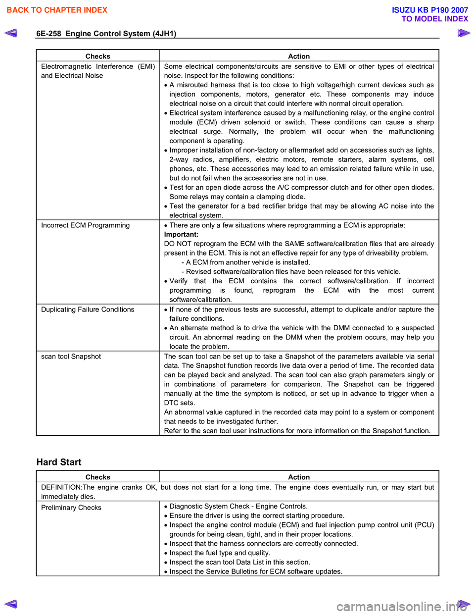
Checks Action
Electromagnetic Interference (EMI)
and Electrical Noise Some electrical components/circuits are sensitive to EMI or other types of electrical
noise. Inspect for the following conditions:
• A misrouted harness that is too close to high voltage/high current devices such as
injection components, motors, generator etc. These components may induce
electrical noise on a circuit that could interfere with normal circuit operation.
• Electrical system interference caused by a malfunctioning relay, or the engine control
module (ECM) driven solenoid or switch. These conditions can cause a sharp
electrical surge. Normally, the problem will occur when the malfunctioning
component is operating.
• Improper installation of non-factory or aftermarket add on accessories such as lights,
2-way radios, amplifiers, electric motors, remote starters, alarm systems, cell
phones, etc. These accessories may lead to an emission related failure while in use,
but do not fail when the accessories are not in use.
• Test for an open diode across the A/C compressor clutch and for other open diodes.
Some relays may contain a clamping diode.
• Test the generator for a bad rectifier bridge that may be allowing AC noise into the
electrical system.
Incorrect ECM Programming • There are only a few situations where reprogramming a ECM is appropriate:
Important:
DO NOT reprogram the ECM with the SAME software/calibration files that are already
present in the ECM. This is not an effective repair for any type of driveability problem. - A ECM from another vehicle is installed.
- Revised software/calibration files have been released for this vehicle.
• Verify that the ECM contains the correct software/calibration. If incorrect
programming is found, reprogram the ECM with the most current
software/calibration.
Duplicating Failure Conditions • If none of the previous tests are successful, attempt to duplicate and/or capture the
failure conditions.
• An alternate method is to drive the vehicle with the DMM connected to a suspected
circuit. An abnormal reading on the DMM when the problem occurs, may help you
locate the problem.
scan tool Snapshot The scan tool can be set up to take a Snapshot of the parameters available via serial
data. The Snapshot function records live data over a period of time. The recorded data
can be played back and analyzed. The scan tool can also graph parameters singly or
in combinations of parameters for comparison. The Snapshot can be triggered
manually at the time the symptom is noticed, or set up in advance to trigger when a
DTC sets.
An abnormal value captured in the recorded data may point to a system or component
that needs to be investigated further.
Refer to the scan tool user instructions for more information on the Snapshot function.
Hard Start
Checks Action
DEFINITION:The engine cranks OK, but does not start for a long time. The engine does eventually run, or may start but
immediately dies.
Preliminary Checks •
Diagnostic System Check - Engine Controls.
• Ensure the driver is using the correct starting procedure.
• Inspect the engine control module (ECM) and fuel injection pump control unit (PCU)
grounds for being clean, tight, and in their proper locations.
• Inspect that the harness connectors are correctly connected.
• Inspect the fuel type and quality.
• Inspect the scan tool Data List in this section.
• Inspect the Service Bulletins for ECM software updates.
BACK TO CHAPTER INDEX
TO MODEL INDEX
ISUZU KB P190 2007
Page 1309 of 6020
Engine Control System (4JH1) 6E-275
Repair Instructions
Engine Control Module (ECM) Replacement
Engine Control Module (ECM) Replacement
Procedure
Important:
If the ECM is to be replaced the following programmed
contents MUST be reprogrammed into the new ECM. • Vehicle identification number (VIN).
• Latest software/calibrations if released. Refer to
Service Programming System (SPS) Description
and Service Programming System (SPS) (Remote
Procedure) or Service Programming System (SPS)
(Pass-Thru Procedure) in this section
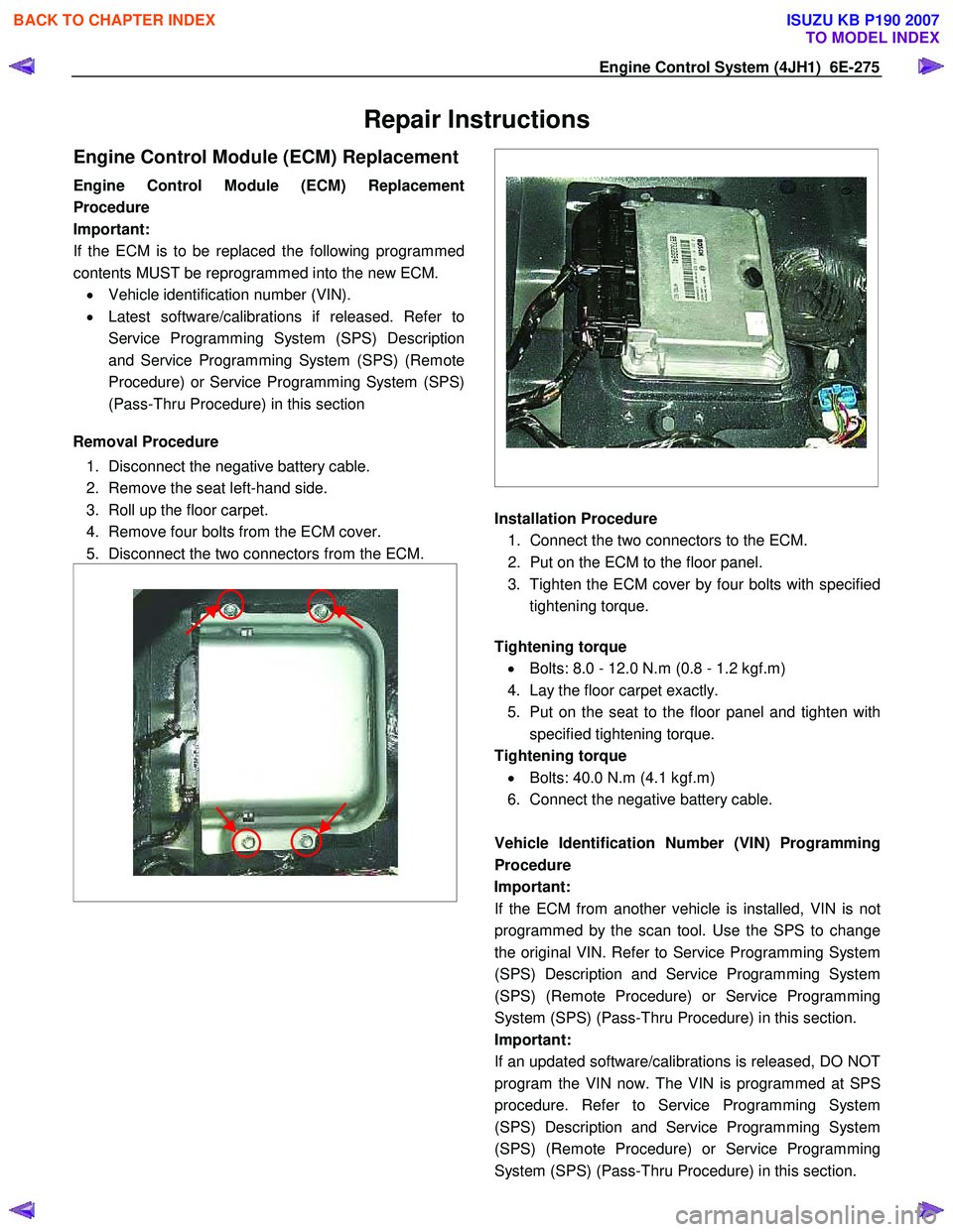
Removal Procedure
1. Disconnect the negative battery cable.
2. Remove the seat left-hand side.
3. Roll up the floor carpet.
4. Remove four bolts from the ECM cover.
5. Disconnect the two connectors from the ECM.
Installation Procedure
1. Connect the two connectors to the ECM.
2. Put on the ECM to the floor panel.
3. Tighten the ECM cover by four bolts with specified tightening torque.
Tightening torque
• Bolts: 8.0 - 12.0 N.m (0.8 - 1.2 kgf.m)
4. Lay the floor carpet exactly.
5. Put on the seat to the floor panel and tighten with specified tightening torque.
Tightening torque • Bolts: 40.0 N.m (4.1 kgf.m)
6. Connect the negative battery cable.
Vehicle Identification Number (VIN) Programming
Procedure
Important: If the ECM from another vehicle is installed, VIN is no
t
programmed by the scan tool. Use the SPS to change
the original VIN. Refer to Service Programming System
(SPS) Description and Service Programming System
(SPS) (Remote Procedure) or Service Programming
System (SPS) (Pass-Thru Procedure) in this section.
Important:
If an updated software/calibrations is released, DO NOT
program the VIN now. The VIN is programmed at SPS
procedure. Refer to Service Programming System
(SPS) Description and Service Programming System
(SPS) (Remote Procedure) or Service Programming
System (SPS) (Pass-Thru Procedure) in this section.
BACK TO CHAPTER INDEX
TO MODEL INDEX
ISUZU KB P190 2007
Page 1310 of 6020
6E-276 Engine Control System (4JH1)
1. Connect the scan tool to the vehicle DLC, with theengine and the scan tool OFF.
2. Turn ON the scan tool.
3. Select Diagnostic > appropriate vehicle identification > Powertrain > 4JH1-TC >
Programming > Program VIN.
4. Input correct VIN reading from stamped VIN o
r
affixed VIN plate on the vehicle.
Select Lock ECU and lock the programmed VIN.
Service Programming System (SPS)
Description
The service programming system (SPS) allows a
technician to program a control module through the data
link connector (DLC). The information transfer circuit that
is used at the DLC is the same serial data circuit used be
the scan tool for retrieving diagnostic trouble codes
(DTCs), displaying data, clearing DTCs etc. This
procedure offers the ability to install software/calibrations
matched to a particular vehicle.
Most control modules have two types of memory. The
software/calibrations reside in the flash memory. The two
types of memory are listed below: • Electrically Erasable Programmable Read Onl
y
Memory (EEPROM).
This type of memory allows selected portions o
f
memory to be programmed while other portions
remain unchanged.
Certain learned values reside in the EEPROM, such as:
- The vehicle identification number (VIN)
- The software/calibrations identification numbers
- The control module security information
• Flash Read Only Memory-Flash Memory
Flash memory has increased memory storage capacity. During programming, all information within
this type of memory is erased, and then replaced
with entirely new information.
Service Programming Methods
The two methods of programming an engine control
module (ECM) are listed below: • Remote Programming
• Pass Thru Programming
For information on programming an ECM using one o
f
the methods listed above, refer to Service Programming
System (SPS) (Remote Procedure) or Service
Programming System (SPS) (Pass-Thru Procedure).
Before Programming a Control Module
Important:
DO NOT program an existing ECM with the identical
software/calibration package. This procedure is not a
short cut to correct the driveability condition. This is an
ineffective repair. An ECM should only be programmed
when the following occurs: • W hen a service procedure instructs you to replace
the ECM. W hen the ECM from another vehicle is
installed, VIN must be changed. And change
vehicle information as necessary such as type o
f
transmission.
• An updated software/calibrations is released.
Ensure that the following conditions are met before
programming an ECM: • The scan tool PCMCIA card is programmed with
the latest software.
• The TIS 2000 is installed with the latest software.
• The hardware key is plugged into the compute
r
port.
• Vehicle system voltage:
- There are no charging system concerns. All charging system concerns must be repaired
before programming the ECM.
- The battery voltage is greater than 12 volts bu
t
less than 16 volts. The battery must be fully
charged before programming the ECM.
-
A battery charger is NOT connected to the
vehicles battery. Incorrect system voltage o
r
voltage fluctuations from a battery charger may
cause programming failure or ECM damage.
- Turn OFF or disable any system that may put a load on the vehicles battery. Turn OFF o
r
disable systems such as:
◊ Heating, ventilation, and air conditioning
(HVAC) systems
◊ Headlights
◊ Room lights
◊ Accessory equipment
• The ignition switch is in the proper position. The
scan tool prompts you to turn ON the ignition, with
the engine OFF. DO NOT change the position o
f
the ignition switch during the programming
procedure unless instructed to do so.
• All tool connections are secure:
- The RS-232 cable
- The connection at the DLC
- The voltage supply circuits
BACK TO CHAPTER INDEX
TO MODEL INDEX
ISUZU KB P190 2007
Page 1311 of 6020
Engine Control System (4JH1) 6E-277
• DO NOT disturb the tool harnesses while
programming. If an interruption occurs during the
programming procedure, programming failure o
r
ECM damage may occur.
• If you are performing the Pass-Thru programming
procedure using a notebook computer without the
power cord, ensure that the internal battery is full
y
charged.
Service Programming System (SPS)
(Remote Procedure)
The Remote Service Programming System (SPS)
method is a three-step process that involves the
following procedures: 1. Connecting the scan tool to the vehicle and obtaining the information from the engine control
module (ECM).
2. Connecting the scan tool to the terminal and downloading a new calibration file from the terminal
into the scan tool memory.
3. Reconnecting the scan tool to the vehicle and uploading the new calibration file into the ECM.
Performing the Remote Procedure 1. Connect the scan tool to the vehicle and obtain the ECM information using the following procedure:
Important:
Ensure the ECM is installed in the vehicle and the batter
y
is fully charged before programming. a. Connect the scan tool to the vehicle data linkconnector (DLC), with the engine and the scan
tool OFF.
b. Turn ON the scan tool.
c. Press Enter at the title screen.
d. Turn ON the ignition, with the engine OFF.
e. Select Service Programming System at the Main Menu.
f. Select Request Info.
g. If there is already stored in the scan tool, the existing data is displayed on the screen. The
scan tool asks user to keep existing data Keep
Data or Continue to request new vehicle
information from the ECM. If there is no data in
the scan tool, it will immediately start vehicle
identification.
h. Enter the vehicle description by following the on- screen instructions based on stamped VIN o
r
affixed VIN plate on the vehicle.
i. During obtaining information, the scan tool is
receiving information from any modules at the
same time. But only ECM information is
displayed on the screen.
j. Turn OFF all accessories and select Continue.
k. Verify that the correct VIN is entered on the scan tool. If the VIN is incorrect, write down the
correct VIN.
2. Turn OFF the scan tool.
3. Disconnect the scan tool from the vehicle.
4. Turn OFF the ignition.
5. Transfer the data from the terminal to the scan tool using the following procedure:
Important:
The TIS supports service programming with the scan
tool scan tool only. a. Connect the scan tool to the terminal.
b. Launch the TIS application at the terminal.
c. Select the Service Programming System at the main screen.
d. Highlight the following information on the Selec
t
Diagnostic Tool and Programming Process
screen: • Select Diagnostic Tool-Select scan tool.
• Select Programming Process-Identif
y
whether an existing ECM is being
reprogrammed or an ECM is being
replaced with a new one.
• Select ECU Location-Select Vehicle.
e. Select Next.
f. Verify the connections on the Preparing fo
r
Communication screen and select Next.
g. Verify the VIN on the Validate Vehicle Identification Number (VIN) screen and selec
t
Next.
Important:
If the ECM is replaced to new one, VIN does no
t
displayed. Input correct VIN reading from stamped VIN
or affixed VIN plate on the vehicle. If the ECM from
another vehicle is installed, input correct VIN by same
way.
h. Highlight Engine on the System Type screen and select Next, if requested.
i. Complete the following information based on the service ID plate on the Validate Vehicle
Data screen until Next is highlighted: • Model
• Model Year
• Engine
• Type of Transmission
BACK TO CHAPTER INDEX
TO MODEL INDEX
ISUZU KB P190 2007
Page 1619 of 6020
6E-2 ENGINE CONTROL SYSTEM (4JK1/4JJ1)
DTC P2127 or P2128 (Flash Code 122) . . . . 6E-265
DTC P2132 or P2133 (Flash Code 123) . . . . 6E-269
DTC P2138, P2139 or P2140 (Flash Code 124, 125 or 126) . . . . . . . . . . . . 6E-274
DTC P2146, P2147 or P2148 (Flash Code 158) . . . . . . . . . . . . . . . . . . . . . 6E-280
DTC P2149, P2150 or P2151 (Flash Code 159) . . . . . . . . . . . . . . . . . . . . . 6E-284
DTC P2227 (Flash Code 71) . . . . . . . . . . . . . 6E-288
DTC P2228 or P2229 (Flash Code 71) . . . . . 6E-291
DTC P2621 or P2622 (Flash Code 94) . . . . . 6E-295
DTC U0001 or U0101 Flash Code 84 or 85) . . . . . . . . . . . . . . . . . . 6E-298
DTC U0167 (Flash Code 177) . . . . . . . . . . . . 6E-299
EGR Control System Check. . . . . . . . . . . . . . 6E-300
Glow Control System Check . . . . . . . . . . . . . 6E-304
In-Tank Fuel Pump System Check . . . . . . . . . 6E-309
Cruise Control System Check . . . . . . . . . . . . 6E-312
Turbocharger Control System Check . . . . . . . 6E-318
Symptoms - Engine Controls . . . . . . . . . . . . . . 6E-321 Symptoms - Engine Controls . . . . . . . . . . . . . 6E-321
Intermittent Conditions . . . . . . . . . . . . . . . . . . 6E-323
Hard Start . . . . . . . . . . . . . . . . . . . . . . . . . . . . 6E-326
Rough, Unstable, or Incorrect Idle and Stalling. . . . . . . . . . . . . . . . . . . . . . . . . . . . . . 6E-328
High Idle Speed . . . . . . . . . . . . . . . . . . . . . . . 6E-330
Cuts Out . . . . . . . . . . . . . . . . . . . . . . . . . . . . . 6E-331
Surges . . . . . . . . . . . . . . . . . . . . . . . . . . . . . . 6E-332
Lack of Power, Sluggishness or Sponginess . . . . . . . . . . . . . . . . . . . . . . . . . . 6E-334
Hesitation, Sag or Stumble. . . . . . . . . . . . . . . 6E-336
Abnormal Combustion Noise . . . . . . . . . . . . . 6E-338
Poor Fuel Economy . . . . . . . . . . . . . . . . . . . . 6E-339
Excessive Smoke (Black Smoke) . . . . . . . . . 6E-341
Excessive Smoke (White Smoke) . . . . . . . . . 6E-343
Repair Instructions . . . . . . . . . . . . . . . . . . . . . . 6E-345 Engine Control Module (ECM) Replacement . . . . . . . . . . . . . . . . . . . . . . . . . 6E-345
Service Programming System (SPS) Description . . . . . . . . . . . . . . . . . . . . . . . . . . 6E-347
Service Programming System (SPS) (Remote Procedure) . . . . . . . . . . . . . . . . . . . 6E-348
Service Programming System (SPS) (Pass-Thru Procedure) . . . . . . . . . . . . . . . . . 6E-349
Description and Operation . . . . . . . . . . . . . . . . 6E-351 Engine Control Module (ECM) Description . . 6E-351
Engine Control Component Description . . . . . 6E-353
Fuel System Description . . . . . . . . . . . . . . . . 6E-357
Fuel System Component Description. . . . . . . 6E-358
Fuel Injection System Description . . . . . . . . . 6E-362
Exhaust Gas Recirculation (EGR) System Description . . . . . . . . . . . . . . . . . . . . 6E-363
Turbocharger Description . . . . . . . . . . . . . . . . 6E-364
Special Tools and Equipment . . . . . . . . . . . . . . 6E-366 Special Tools and Equipment . . . . . . . . . . . . . 6E-366
BACK TO CHAPTER INDEX
TO MODEL INDEX
ISUZU KB P190 2007
Page 1943 of 6020
6E-326 ENGINE CONTROL SYSTEM (4JK1/4JJ1)
Temperature Sensitivity• An intermittent condition may occur when a component/ connection reaches normal
operating temperature. The condition may occur only when the component/
connection is cold, or only when the component/ connection is hot.
• Freeze Frame, Failure Records or Snapshot Data may help with this type of intermittent conditions, where applicable.
• If the intermittent is related to heat, review the data for a relationship with the following:
- High ambient temperatures.
- Underhood/ engine generated heat.
- Circuit generated heat due to a poor connection, or high electrical load.
- Higher than normal load conditions, towing, etc..
• If the intermittent is related to cold, review the data for the following: - Low ambient temperatures-In extremely low temperatures, ice may form in aconnection or component. Test for water intrusion.
- The condition only occurs on a cold start.
- The condition goes away when the vehicle warms up.
• Information from the customer may help to determine if the trouble follows a pattern that is temperature related.
Electromagnetic Interference (EMI)
and Electrical Noise Some electrical components/ circuits are sensitive to EMI or other types of electrical
noise. Inspect the following conditions:
• A misrouted harness that is too close to high voltage/ high current devices such as injection components, motors, generator etc. These components may induce
electrical noise on a circuit that could interfere with normal circuit operation.
• Electrical system interference caused by a malfunctioning relay, or the ECM driven solenoid or switch. These conditions can cause a sharp electrical surge. Normally,
the problem will occur when the malfunctioning component is operating.
• Improper installation of non-factory or aftermarket add on accessories such as lights, 2-way radios, amplifiers, electric motors, remote starters, alarm systems, cell
phones, etc. These accessories may lead to an emission related failure while in
use, but do not fail when the accessories are not in use.
• Test for any open diodes. Some relays may contain a clamping diode.
• Test the generator for a bad rectifier bridge that may be allowing AC noise into the electrical system.
Incorrect ECM Programming • There are only a few situations where reprogramming a ECM is appropriate:
- An ECM from another vehicle is installed.
- Revised software/ calibration files have been released for this vehicle.
Important: DO NOT reprogram the ECM with the SAME software/ calibration files that
are already present in the ECM. This is not an effective repair for any type of driveability
problem.
• Verify that the ECM contains the correct software/ calibration. If incorrect programming is found, reprogram the ECM with the most current software/
calibration.
Duplicating Failure Conditions • If none of the previous tests are successful, attempt to duplicate and/ or capture the failure conditions.
• Freeze Frame/ Failure Records data, where applicable, contains the conditions that were present when the DTC set.
- Review and record Freeze Frame/ Failure Records data.
- Operate the vehicle under the same conditions that were noted in Freeze Frame/ Failure Records data, as closely as possible. The vehicle must also be
operating within the Conditions for Running the DTC. Refer to Conditions for
Running the DTC in the supporting text of the DTC being diagnosed.
• An alternate method is to drive the vehicle with the DMM connected to a suspected circuit. An abnormal reading on the DMM when the problem occurs, may help you
locate the problem.
Checks
Action
BACK TO CHAPTER INDEX
TO MODEL INDEX
ISUZU KB P190 2007
Page 1965 of 6020
6E-348 ENGINE CONTROL SYSTEM (4JK1/4JJ1)
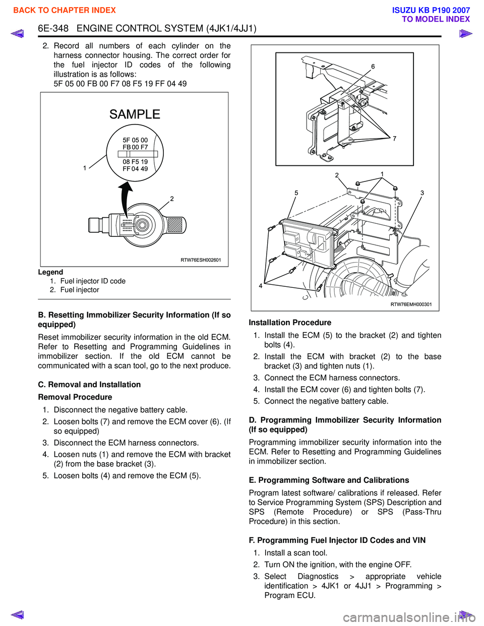
2. Record all numbers of each cylinder on theharness connector housing. The correct order for
the fuel injector ID codes of the following
illustration is as follows:
5F 05 00 FB 00 F7 08 F5 19 FF 04 49
Legend
1. Fuel injector ID code
2. Fuel injector
B. Resetting Immobilizer Security Information (If so
equipped)
Reset immobilizer security information in the old ECM.
Refer to Resetting and Programming Guidelines in
immobilizer section. If the old ECM cannot be
communicated with a scan tool, go to the next produce.
C. Removal and Installation
Removal Procedure 1. Disconnect the negative battery cable.
2. Loosen bolts (7) and remove the ECM cover (6). (If so equipped)
3. Disconnect the ECM harness connectors.
4. Loosen nuts (1) and remove the ECM with bracket (2) from the base bracket (3).
5. Loosen bolts (4) and remove the ECM (5). Installation Procedure
1. Install the ECM (5) to the bracket (2) and tighten bolts (4).
2. Install the ECM with bracket (2) to the base bracket (3) and tighten nuts (1).
3. Connect the ECM harness connectors.
4. Install the ECM cover (6) and tighten bolts (7).
5. Connect the negative battery cable.
D. Programming Immobilizer Security Information
(If so equipped)
Programming immobilizer security information into the
ECM. Refer to Resetting and Programming Guidelines
in immobilizer section.
E. Programming Software and Calibrations
Program latest software/ calibrations if released. Refer
to Service Programming System (SPS) Description and
SPS (Remote Procedure) or SPS (Pass-Thru
Procedure) in this section.
F. Programming Fuel Injector ID Codes and VIN 1. Install a scan tool.
2. Turn ON the ignition, with the engine OFF.
3. Select Diagnostics > appropriate vehicle identification > 4JK1 or 4JJ1 > Programming >
Program ECU.
RTW76ESH002601
5F 05 00
FB 00 F7
SAMPLE
08 F5 19
FF 0 4 49
2
1
RTW76EMH000301
5
1
2
3
4
6
7
BACK TO CHAPTER INDEX
TO MODEL INDEX
ISUZU KB P190 2007