2007 ISUZU KB P190 bolt pattern
[x] Cancel search: bolt patternPage 280 of 6020

POWER-ASSISTED STEERING SYSTEM 3B-19
Disassembly
1. Clean the oil pump with solvent (plug the discharge
and suction ports to prevent the entry of solvent).
Be careful not to expose the oil seal of shaft
assembly to solvent.
2. Remove the bolt, suction pipe and O-ring.
3. Remove the connector, O-ring, relief valve and spring.
4. Remove the bolt, rear housing and O-ring.
5. Remove the snap ring.
6. Remove the shaft assembly.
7. Remove the oil seal.
CAUTION: When removing the oil seal, be careful
not to damage the housing.
8. Remove the pump cartridge assembly from the front housing.
9. Remove two O-rings.
Inspection and Repair
Make all necessary adjustments, repairs, and part
replacements if wear, damage, or other problems are
discovered during inspection.
Rotor
442RS002
Check that the groove in the vane is free from excessive
wear and that the vane slides smoothly. W hen part
replacement becomes necessary, the pump cartridge
should be replaced as a subassembly.
Vane
442RS003
Sliding faces of the vane should be free from wear.
(Particularly the curved face at the tip that contact with
the cam should be free from wear and distortion). W hen
part replacement becomes necessary, the pump
cartridge should be replaced as a subassembly.
Cam
The inner face of the cam should have a uniform
contact pattern without a sign of step wear. W hen part
replacement becomes necessary, the pump cartridge
should be replaced as a subassembly.
Side Plate
The sliding faces of parts must be free from step wear
(more than 0.01 mm (0.0004 in)), which can be felt b
y
the finger nail.
The parts with minor scores may be reused after lapping
the face.
Relief Valve
The sliding face of the valve must be free from burrs
and damage. The parts with minor scores may be
reused after smoothing with emery cloth (#800 or finer).
Shaft
Oil seal sliding faces must be free from a step wear
which can be felt by the finger nail. Bushing fitting face
must be free from damage and wear.
O-ring, Oil Seal, Snap Ring
Be sure to discard used parts, and always use new
parts for installation. Prior to installation, lubricate all
seals and rings with power steering fluid.
BACK TO CHAPTER INDEX
TO MODEL INDEX
ISUZU KB P190 2007
Page 285 of 6020

3B-24 POWER-ASSISTED STEERING SYSTEM
Disassembly
1. Clean the oil pump with solvent (plug the discharge
and suction ports to prevent the entry of solvent).
Be careful not to expose the oil seal of the shaft assembly to solvent.
2. Remove the bolt, suction pipe and O-ring.
3. Remove the nut and bracket.
4. Remove the nut, washer and joint.
5. Remove the connector, O-ring, relief valve and spring.
6. Remove the bolt, rear housing and O-ring.
7. Remove the pump cartridge assembly and the side plate from the shaft. Remove two O-rings.
Inspection and Repair
Make all necessary adjustments, repairs, and part
replacements if wear, damage, or other problems are
discovered during inspection.
Rotor
442RS002
Check that the groove in the vane is free from excessive
wear and that the vane slides smoothly. W hen part
replacement becomes necessary, the pump cartridge
should be replaced as a subassembly.
Vane
442RS003
Sliding faces of the vane should be free from wear. (In
particular the curved face at the tip that makes contact
with the cam should be free from wear and distortion).
W hen part replacement becomes necessary, the pump
cartridge should be replaced as a subassembly.
Cam
The inner face of the cam should have a uniform
contact pattern without a sign of step wear. W hen part
replacement becomes necessary, the pump cartridge
should be replaced as a subassembly.
Side Plate
The sliding faces of parts must be free from step wear
(more than 0.01 mm (0.0004 in)), which can be felt by a
finger nail.
Parts with minor scores may be reused after lapping the
face.
Relief Valve
The sliding face of the valve must be free from burrs
and damage. Parts with minor scores may be reused
after smoothing with emery cloth (#800 or finer).
Shaft and Housing Assembly
The bushing fitting face on the shaft must be free from
damage and wear.
O-ring
Be sure to discard used parts, and always use new
parts for installation. Prior to installation, lubricate all
seals and rings with power steering fluid.
BACK TO CHAPTER INDEX
TO MODEL INDEX
ISUZU KB P190 2007
Page 476 of 6020

4B-32 REAR AXLE
16. Tighten the bolt to the specified torque.
Torque :
φ220mm : 108 N ⋅m (11 kgf ⋅m/80 lb ⋅ft)
φ194mm : 98 N ⋅m (10 kgf ⋅m/72 lb ⋅ft)
425RS036
• Measure the amount of run-out of the ring gear at
its rear face. It should be 0.05 mm (0.002 in) o
r
less
Gear Tooth Contact Pattern Check and Adjustment
1.
Apply a thin coat of Prussian blue or equivalent
to the faces of the 7–8 teeth of the ring gear.
Check the impression of contact on the ring gea
r
teeth and make necessary adjustment as
described in illustration if the contact is
abnormal.
425RS038
Legend
1. Heel
2. Toe
3. Concave Side(Coast)
4. Convex Side(Drive)
BACK TO CHAPTER INDEX
TO MODEL INDEX
ISUZU KB P190 2007
Page 540 of 6020

4C1-36 FRONT WHEEL DRIVE
18. Bolt
Bolt Torque N⋅m (kgf ⋅m/lb ⋅ft)
98 (10.0/72)
Measure the amount of run-out of the ring gear at its rear face.
mm(in)
Standard Limit
0.02 (0.001) 0.05 (0.002)
Gear Tooth Contact Pattern Check and Adjustment
Apply a thin coat of prussian blue or equivalent to the faces of
the 7 - 8 teeth of the ring gear. Check the impression of
contact on the ring gear teeth and make necessary adjustment
as described below if the contact is abnormal.
BACK TO CHAPTER INDEX
TO MODEL INDEX
ISUZU KB P190 2007
Page 797 of 6020

6 – 12 TROUBLESHOOTING
10. Abnormal Engine Noise
10–1 Engine knocking
Step Action Value(s) Yes No
1 Was the injection nozzle pressure or injection spray
pattern OK? —
Go to Step 2 Replace the
injection nozzle
2 Was the compression pressure OK? 3.0 MPa
(31.0 kg/cm2,
441 psi) at 200 rpm Go to Step 3 Replace the
cylinder head gasket or
piston ring
3 Are any DTC stored? — Go to indicated
DTC Solved
10–2 Gas leakage noise
Step Action Value(s) Yes No
1 Was the exhaust pipe loose or broken? — Retighten or
replace the
exhaust pipe Go to Step 2
2 Was the exhaust manifold loose? —
Retighten or
replace the exhaust
manifold. Or replace the exhaust
manifold gasket Go to Step 3
3 Was the injection nozzle loose? — Retighten or
replace the
injection nozzle fixing bolt Go to Step 4
4 Was the cylinder head gasket broken? — Replace the
cylinder head gasket Go to Step 5
5 Are any DTC stored? — Go to indicated
DTC Solved
BACK TO CHAPTER INDEX
TO MODEL INDEX
ISUZU KB P190 2007
Page 1473 of 6020

ENGINE MECHANICAL (4JK1/4JJ1) 6A-113
Inspection
1. Visual inspection
• Inspect the flywheel friction surface for cracks
and damages, and replace it if it has
abnormality.
• Inspect the tooth part of the ring gear, replace
the ring gear if it has damage or serious wear.
2. Measurement of the friction surface • Measure the depth of the friction surface of the
flywheel.
•
Adjust it if the measured value is within the
standard value and the limit.
• If the measured value exceeds the limit,
replace the flywheel.
Depth of the friction surface of the flywheel mm (in)
Standard 18 (0.7087)
Limit 19 (0.7480)
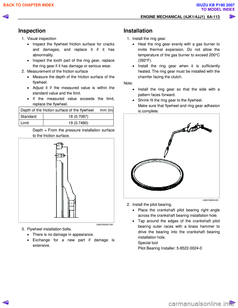
Depth = From the pressure installation surface
to the friction surface.
LNW 21BSH011901
3. Flywheel installation bolts.
• There is no damage in appearance.
• Exchange for a new part if damage is
extensive.
Installation
1. Install the ring gear.
• Heat the ring gear evenly with a gas burner to
invite thermal expansion. Do not allow the
temperature of the gas burner to exceed 200°C
(392°F).
• Install the ring gear when it is sufficientl
y
heated. The ring gear must be installed with the
chamfer facing the clutch.
Note: • Install the ring gear so that the side with a
pattern faces forward.
• Shrink fit the ring gear to the flywheel.
Make sure that flywheel and ring gear adhesion is complete.
LNW 21BSH01201
2. Install the pilot bearing.
• Place the crankshaft pilot bearing right angle
across the crankshaft bearing installation hole.
• Tap around the edges of the crankshaft pilot
bearing outer races with a brass hammer to
drive the bearing into the crankshaft bearing
installation hole.
Special tool
Pilot Bearing Installer: 5-8522-0024-0
BACK TO CHAPTER INDEX
TO MODEL INDEX
ISUZU KB P190 2007
Page 2049 of 6020

ENGINE MECHANICAL (C24SE) 6A-35
Camshaft Housing, Removal and
Installation
Cylinder Head
Important!
Remove cylinder head only from cold engine (room
temperature).
Removal
1. Remove ground cable from battery.
2. Open radiator drain tap and collect coolant.
3. Remove air intake hose.
4. Remove all cable connections, hoses and lines to the cylinder head.
5. Remove accelerator cable on the throttle valve.
6. Remove V-belt for alternator.
7. Remove front toothed belt cover according to the
corresponding operation.
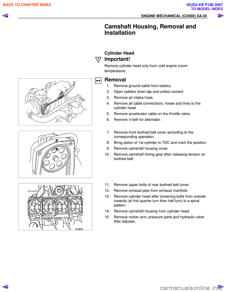
8. Bring piston of 1st cylinder to TDC and mark the position.
9. Remove camshaft housing cover.
10. Remove camshaft timing gear after releasing tension on toothed belt.
11. Remove upper bolts of rear toothed belt cover.
12. Remove exhaust pipe from exhaust manifold.
13. Remove cylinder head after loosening bolts from outside inwards (at first quarter turn then half turn) in a spiral
pattern.
14. Remove camshaft housing from cylinder head.
15. Remove rocker arm, pressure parts and hydraulic valve lifter adjuster.
BACK TO CHAPTER INDEX
TO MODEL INDEX
ISUZU KB P190 2007
Page 2050 of 6020

6A-36 ENGINE MECHANICAL (C24SE)
Clean
All sealing surfaces, drill holes in cylinder head bolts.
Check cylinder block and cylinder head for plane surface
according to the corresponding operations.
Installation
1. Install cylinder head sealing with marking "OBEN/TOP"
facing upwards and to right side of engine.
2. Install cylinder head on cylinder block.
3. Install hydraulic valve lash adjuster, pressure parts and rocker arm - molybdenum disulphate paste.
4. Install camshaft housing-Sealing Compound TB-1207C or equivalent.
Important!
Use new cylinder head bolts.
Screw in bolts until they rest on cover.
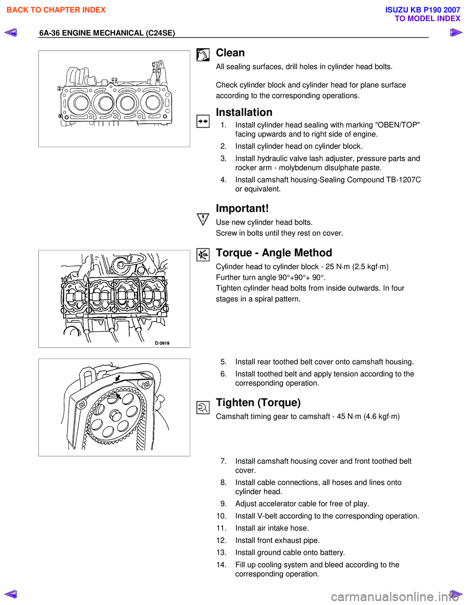
Torque - Angle Method
Cylinder head to cylinder block - 25 N ⋅m (2.5 kgf ⋅m)
Further turn angle 90 °+90 °+ 90 °.
Tighten cylinder head bolts from inside outwards. In four
stages in a spiral pattern.
5. Install rear toothed belt cover onto camshaft housing.
6. Install toothed belt and apply tension according to the corresponding operation.
Tighten (Torque)
Camshaft timing gear to camshaft - 45 N ⋅m (4.6 kgf ⋅m)
7. Install camshaft housing cover and front toothed belt
cover.
8. Install cable connections, all hoses and lines onto cylinder head.
9. Adjust accelerator cable for free of play.
10. Install V-belt according to the corresponding operation.
11. Install air intake hose.
12. Install front exhaust pipe.
13. Install ground cable onto battery.
14. Fill up cooling system and bleed according to the corresponding operation.
BACK TO CHAPTER INDEX
TO MODEL INDEX
ISUZU KB P190 2007