Page 5478 of 6020

8A-540 ELECTRICAL-BODY AND CHASSIS
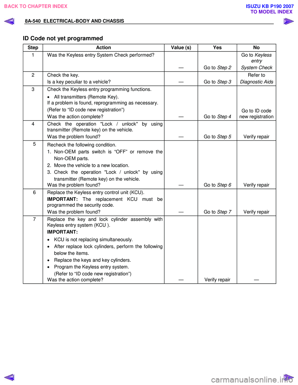
ID Code not yet programmed
Step Action Value (s) Yes No
1 W as the Keyless entry System Check performed?
— Go to Step 2 Go to
Keyless
entry
System Check
2 Check the key. Is a key peculiar to a vehicle? — Go to Step 3 Refer to
Diagnostic Aids
3 Check the Keyless entry programming functions.
• All transmitters (Remote Key).
If a problem is found, reprogramming as necessary.
(Refer to “ID code new registration”)
W as the action complete? — Go to Step 4 Go to ID code
new registration
4 Check the operation "Lock / unlock" by using transmitter (Remote key) on the vehicle.
W as the problem found? — Go to Step 5 Verify repair
5
Recheck the following condition.
1. Non-OEM parts switch is “OFF” or remove the Non-OEM parts.
2. Move the vehicle to a new location.
3. Check the operation "Lock / unlock" by using transmitter (Remote key) on the vehicle.
W as the problem found? — Go to Step 6 Verify repair
6 Replace the Keyless entry control unit (KCU).
IMPORTANT: The replacement KCU must be
programmed the security code.
W as the problem found? — Go to Step 7 Verify repair
7 Replace the key and lock cylinder assembly with
Keyless entry system (KCU ).
IMPORTANT:
• KCU is not replacing simultaneously.
• After replace lock cylinders, perform the following
below the items.
• Replace the keys and key cylinders.
• Program the Keyless entry system.
(Refer to “ID code new registration”)
W as the action complete? — Verify repair —
BACK TO CHAPTER INDEX
TO MODEL INDEXISUZU KB P190 2007
Page 5479 of 6020

ELECTRICAL-BODY AND CHASSIS 8A-541
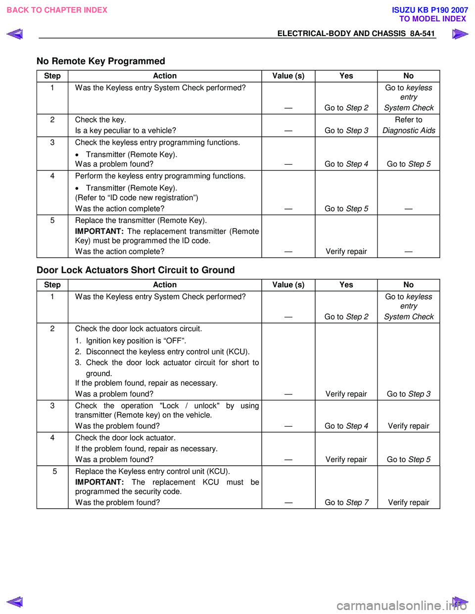
No Remote Key Programmed
Step Action Value (s) Yes No
1 W as the Keyless entry System Check performed?
— Go to Step 2 Go to
keyless
entry
System Check
2 Check the key. Is a key peculiar to a vehicle? — Go to Step 3 Refer to
Diagnostic Aids
3 Check the keyless entry programming functions.
• Transmitter (Remote Key).
W as a problem found? — Go to Step 4 Go to Step 5
4 Perform the keyless entry programming functions.
• Transmitter (Remote Key).
(Refer to “ID code new registration”)
W as the action complete? — Go to Step 5 —
5 Replace the transmitter (Remote Key).
IMPORTANT: The replacement transmitter (Remote
Key) must be programmed the ID code.
W as the action complete? — Verify repair —
Door Lock Actuators Short Circuit to Ground
Step Action Value (s) Yes No
1 W as the Keyless entry System Check performed?
— Go to Step 2 Go to
keyless
entry
System Check
2 Check the door lock actuators circuit.
1. Ignition key position is “OFF”.
2. Disconnect the keyless entry control unit (KCU).
3. Check the door lock actuator circuit for short to ground.
If the problem found, repair as necessary.
W as a problem found? — Verify repair Go to Step 3
3 Check the operation "Lock / unlock" by using
transmitter (Remote key) on the vehicle.
W as the problem found? — Go to Step 4 Verify repair
4 Check the door lock actuator.
If the problem found, repair as necessary.
W as a problem found? — Verify repair Go to Step 5
5 Replace the Keyless entry control unit (KCU).
IMPORTANT: The replacement KCU must be
programmed the security code.
W as the problem found? — Go to Step 7 Verify repair
BACK TO CHAPTER INDEX
TO MODEL INDEXISUZU KB P190 2007
Page 5481 of 6020
ELECTRICAL-BODY AND CHASSIS 8A-543
RUW 580SH001101
Remove Transmitter (Remote Key)
Replacing the battery in the transmitter (remote key)
Replace the battery(2) as soon as the range of the remote
control starts to become reduced.
Open the underside of the transmitter (remote key) by
removing the battery cover(1) with a screwdriver as shown in
the illustration.
Replace the battery, ensuring that it is inserted correctly.
Replace the battery cover so that it engages audibly. Make
sure that you dispose of old batteries in accordance with
environmental protection regulations.
RUW 580SH003901
BACK TO CHAPTER INDEX
TO MODEL INDEXISUZU KB P190 2007
Page 5482 of 6020
8A-544 ELECTRICAL-BODY AND CHASSIS
Keyless Entry System
General Description
The system’s main features are summarized as follows.
・ Keyless entry with visual feedback
・ Highly secure encrypted transmission format
incorporating rolling code strategy
・ Field programmable remote keys
・ Door lock control
・ Illuminated entry with fade out
・ Illuminated exit
・ Remote door lock / ignition key interlock
・ Door ajar warning indicator in the cluster
BACK TO CHAPTER INDEX
TO MODEL INDEXISUZU KB P190 2007
Page 5517 of 6020
ELECTRICAL-BODY AND CHASSIS 8A-579
Remote key
Remove Key Assembly
Replacing the battery in the remote control unit
Replace the battery as soon as the range of the remote control
starts to become reduced.
Open the underside of the remote control unit by removing the
battery cover with a screwdriver as shown in the illustration.
Replace the battery, ensuring that it is inserted correctly.
Replace the battery cover so that it engages audibly. The
battery change must be performed within 3 minutes, otherwise
the remote control will have to be reprogrammed. Make sure
that you dispose of old batteries in accordance with
environmental protection regulations.
604RW 055
BACK TO CHAPTER INDEX TO MODEL INDEXISUZU KB P190 2007
Page 5518 of 6020
8A-580 ELECTRICAL-BODY AND CHASSIS
TECH-2 OPERATION AND PROGRAMING
KEYLESS ENTRY
General Description
W hen the anti-theft and keyless entry control unit and/or the
transmitters (remote keys) are replaced, the security codes
and/or transmitter ID codes must be programmed by using he
Tech-2. The following pages show the procedures to program
in regard to the anti-theft and keyless entry system. Please
refer to Tech-2 scan tool user’s guide in detail.
901RW 180
Legend
(1) PCMCIA Card (4) DLC Cable
(2) RS 232 Loop Back Connector (5)Tech–2
(3) SAE 16/19 Adaptor
BACK TO CHAPTER INDEX TO MODEL INDEXISUZU KB P190 2007
Page 5524 of 6020
8A-586 ELECTRICAL-BODY AND CHASSIS
RTW 38DSH001101
4. Check the display of Tech-2 and press “Confirm”
key.
RTW 38DSH001201
5. Check the display of Tech-2 and press “Confirm”
key.
060R200289
Program Remote Key
To program remote control key code in the control
unit.
1. Check the display of Tech-2 and press “Confirm”
key.
BACK TO CHAPTER INDEX TO MODEL INDEXISUZU KB P190 2007
Page 5955 of 6020

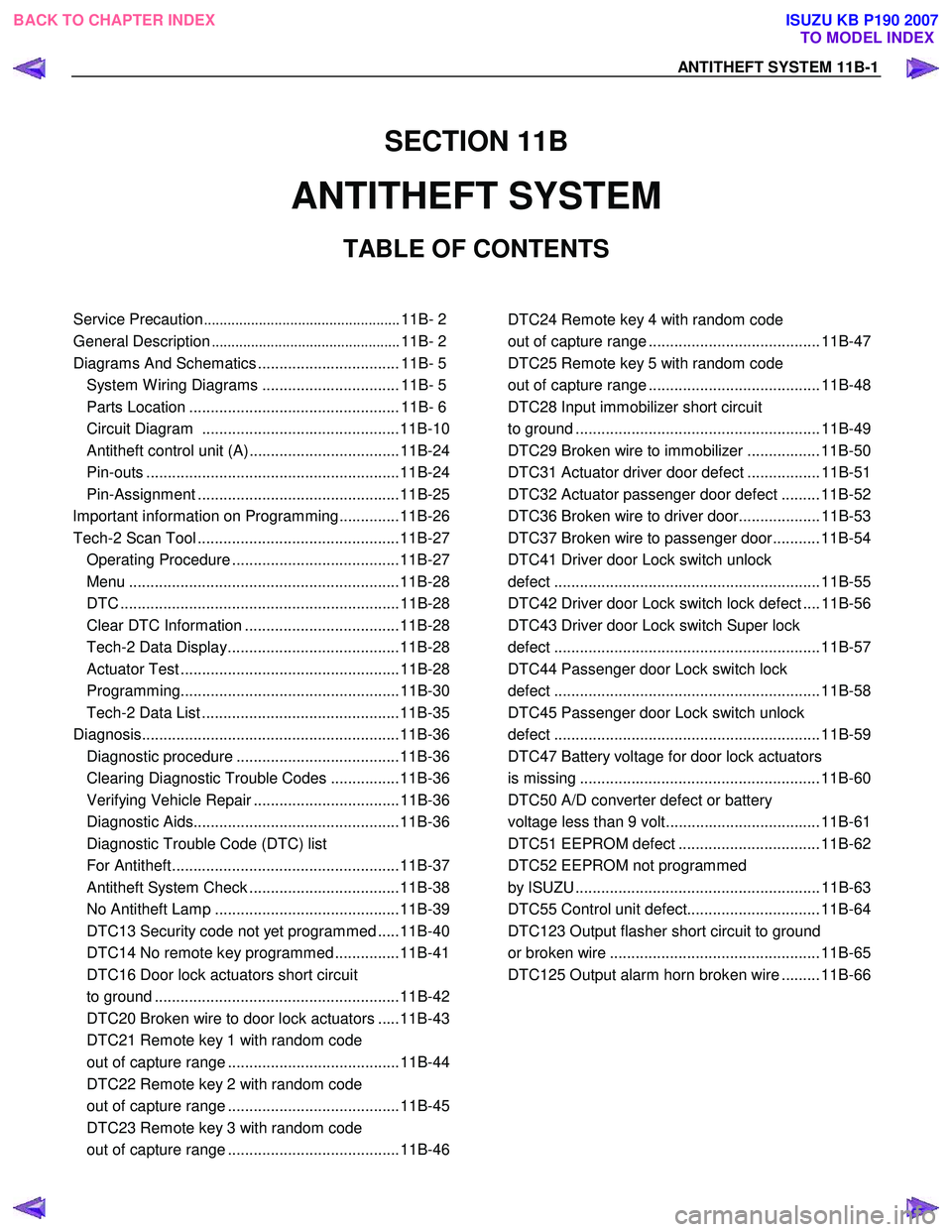
ANTITHEFT SYSTEM 11B-1
SECTION 11B
ANTITHEFT SYSTEM
TABLE OF CONTENTS
Service Precaution .................................................. 11B- 2
General Description ................................................ 11B- 2
Diagrams And Schematics ................................. 11B- 5 System W iring Diagrams ................................ 11B- 5
Parts Location ................................................. 11B- 6
Circuit Diagram ..............................................11B-10
Antitheft control unit (A) ...................................11B-24
Pin-outs ...........................................................11B-24
Pin-Assignment ...............................................11B-25
lmportant information on Programming..............11B-26
Tech-2 Scan Tool ...............................................11B-27 Operating Procedure .......................................11B-27
Menu ...............................................................11B-28
DTC .................................................................11B-28
Clear DTC Information ....................................11B-28
Tech-2 Data Display........................................11B-28
Actuator Test ...................................................11B-28
Programming...................................................11B-30
Tech-2 Data List ..............................................11B-35
Diagnosis............................................................11B-36 Diagnostic procedure ......................................11B-36
Clearing Diagnostic Trouble Codes ................11B-36
Verifying Vehicle Repair ..................................11B-36
Diagnostic Aids................................................11B-36
Diagnostic Trouble Code (DTC) list
For Antitheft.....................................................11B-37
Antitheft System Check ...................................11B-38
No Antitheft Lamp ...........................................11B-39
DTC13 Security code not yet programmed .....11B-40
DTC14 No remote key programmed ...............11B-41
DTC16 Door lock actuators short circuit
to ground .........................................................11B-42
DTC20 Broken wire to door lock actuators .....11B-43
DTC21 Remote key 1 with random code
out of capture range ........................................11B-44
DTC22 Remote key 2 with random code
out of capture range ........................................11B-45
DTC23 Remote key 3 with random code
out of capture range ........................................11B-46
DTC24 Remote key 4 with random code
out of capture range ........................................ 11B-47
DTC25 Remote key 5 with random code
out of capture range ........................................ 11B-48
DTC28 Input immobilizer short circuit
to ground ......................................................... 11B-49
DTC29 Broken wire to immobilizer ................. 11B-50
DTC31 Actuator driver door defect ................. 11B-51
DTC32 Actuator passenger door defect ......... 11B-52
DTC36 Broken wire to driver door................... 11B-53
DTC37 Broken wire to passenger door........... 11B-54
DTC41 Driver door Lock switch unlock
defect .............................................................. 11B-55
DTC42 Driver door Lock switch lock defect .... 11B-56
DTC43 Driver door Lock switch Super lock
defect .............................................................. 11B-57
DTC44 Passenger door Lock switch lock
defect .............................................................. 11B-58
DTC45 Passenger door Lock switch unlock
defect .............................................................. 11B-59
DTC47 Battery voltage for door lock actuators
is missing ........................................................ 11B-60
DTC50 A/D converter defect or battery
voltage less than 9 volt.................................... 11B-61
DTC51 EEPROM defect ................................. 11B-62
DTC52 EEPROM not programmed
by ISUZU ......................................................... 11B-63
DTC55 Control unit defect............................... 11B-64
DTC123 Output flasher short circuit to ground
or broken wire ................................................. 11B-65
DTC125 Output alarm horn broken wire ......... 11B-66
BACK TO CHAPTER INDEX TO MODEL INDEX
ISUZU KB P190 2007