2007 ISUZU KB P190 switches
[x] Cancel search: switchesPage 580 of 6020

4C2-2 SHIFT ON THE FLY SYSTEM
SHIFT ON THE FLY SYSTEM
Outline of Shift on The Fly System
The shift on the fly system switches between 2 wheel
drive (2W D) and 4 wheel drive (4W D) electrically b
y
driver's pressing the 4W D switch (push button type) on
instrument panel.
This system controls below operations.
1. Shifting the transfer front output gear (Connecting to,
and disconnecting from, front propeller shaft b
y
motor actuator).
2. Retrial of shifting the transfer front output gear.
3. Connecting front wheels to, and disconnecting them from, the front axles by axle motor actuator.
4. Indicator on instrument panel.
5. 4W D out signal to other Electronic Hydraulic Control Unit.
System Diagrams
RUW 34BLF000201
BACK TO CHAPTER INDEX
TO MODEL INDEX
ISUZU KB P190 2007
Page 638 of 6020

BRAKE CONTROL SYSTEM 5A-45
Braking Sound (From EHCU) Is Heard While Not Braking
Step Action Value(s) Yes No
1 Is this the first vehicle start after engine start?
- It is self
checking sound
Normal. Go to Step 2
2 Is vehicle speed at 15 km/h or 30 km/h?
- It is self
checking sound
Normal. Go to Step 3
3 Check for the following condition: • At the time of shift down or clutch operation.
• At the time of low road friction drive (ice or snow on road) or rough road drive.
• At the time of high-speed turn.
• At the time of passing curb.
• At the time of operating electrical equipment switches.
• At the time of racing the engine. Did it occur under any of the conditions above? - ABS may
sometimes be
actuated even when brake pedal is not applied. Go to Step 4
4 Is there play in each or any sensor/wheel speed sensor rotor? - Repair.
Go to Step 7 Go to Step 5
5 Damage or powdered iron sticking to each or any sensor/wheel speed sensor rotor? - Repair.
Go to Step 7 Go to Step 6
6 Is each sensor normal? Note: Check the EHCU type for specification, the
EHCU is replaced.
(Specification; 2W D or 4W D Model)
- Check
harness/
connector for suspected
disconnection
If no
disconnection is found,
replace EHCU
Go to Step 7 Repair.
Go to Step 7
7 Reconnect all components, ensure all components are properly mounted.
Is this step finished? - Repeat the
“Basic
diagnostic
flow chart” Go to Step 7
BACK TO CHAPTER INDEX
TO MODEL INDEX
ISUZU KB P190 2007
Page 1015 of 6020
6D – 14 ENGINE ELECTRICAL
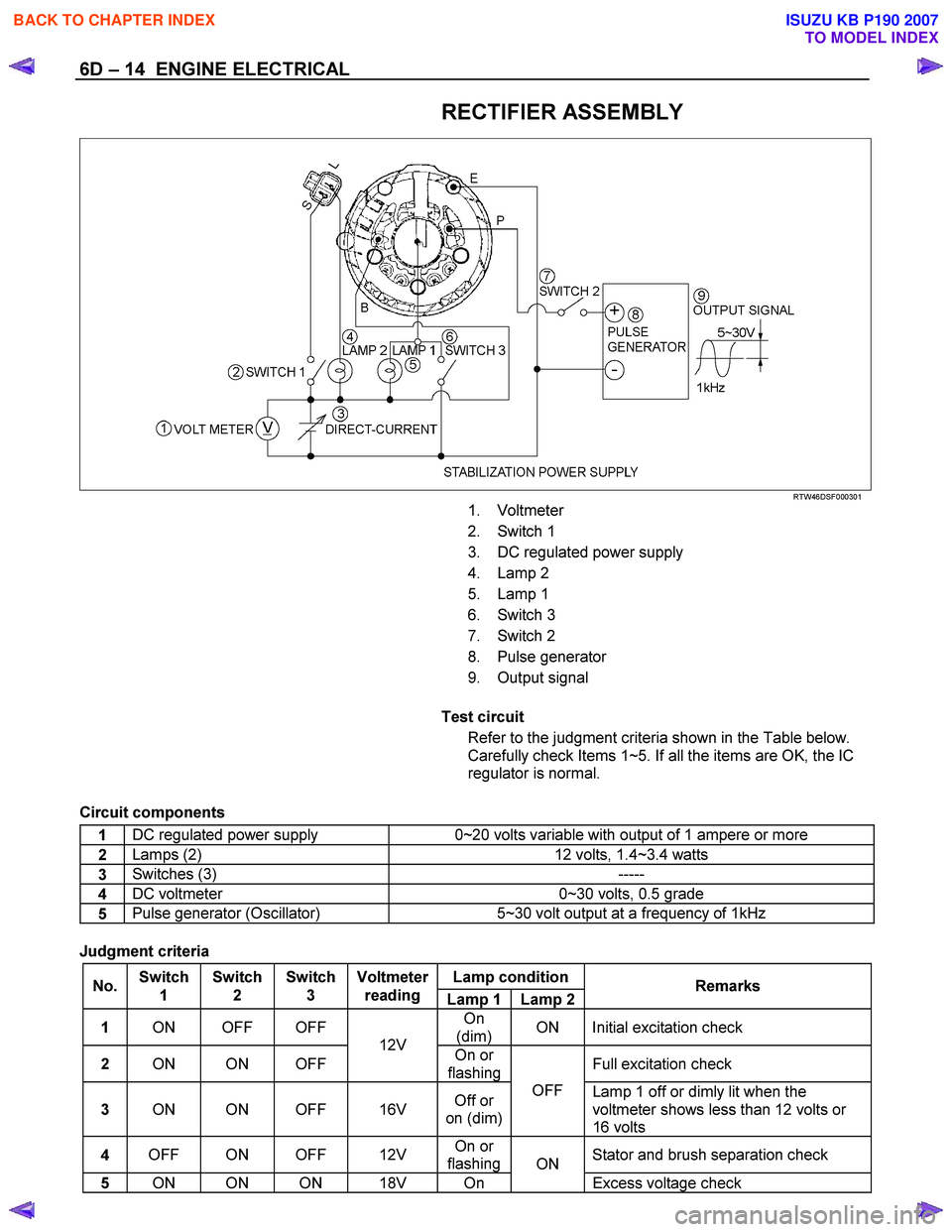
RECTIFIER ASSEMBLY
RTW46DSF000301
1. Voltmeter
2. Switch 1
3. DC regulated power supply
4. Lamp 2
5. Lamp 1
6. Switch 3
7. Switch 2
8. Pulse generator
9. Output signal
Test circuit
Refer to the judgment criteria shown in the Table below.
Carefully check Items 1~5. If all the items are OK, the IC
regulator is normal.
Circuit components
1 DC regulated power supply 0~20 volts variable with output of 1 ampere or more
2 Lamps (2)
12 volts, 1.4~3.4 watts
3 Switches (3)
-----
4 DC voltmeter
0~30 volts, 0.5 grade
5 Pulse generator (Oscillator)
5~30 volt output at a frequency of 1kHz
Judgment criteria
Lamp condition
No. Switch
1 Switch
2 Switch
3 Voltmeter
reading Lamp 1 Lamp 2 Remarks
1
ON OFF OFF On
(dim) ON Initial excitation check
2
ON ON OFF 12V
On or
flashing Full excitation check
3
ON ON OFF 16V Off or
on (dim) OFF
Lamp 1 off or dimly lit when the
voltmeter shows less than 12 volts or
16 volts
4 OFF ON OFF 12V On or
flashing Stator and brush separation check
5
ON ON ON 18V On ON
Excess voltage check
BACK TO CHAPTER INDEX
TO MODEL INDEX
ISUZU KB P190 2007
Page 1317 of 6020
Engine Control System (4JH1) 6E-283
Description And Operation
Engine Control Module (ECM) Description
RTW 66ESH001201
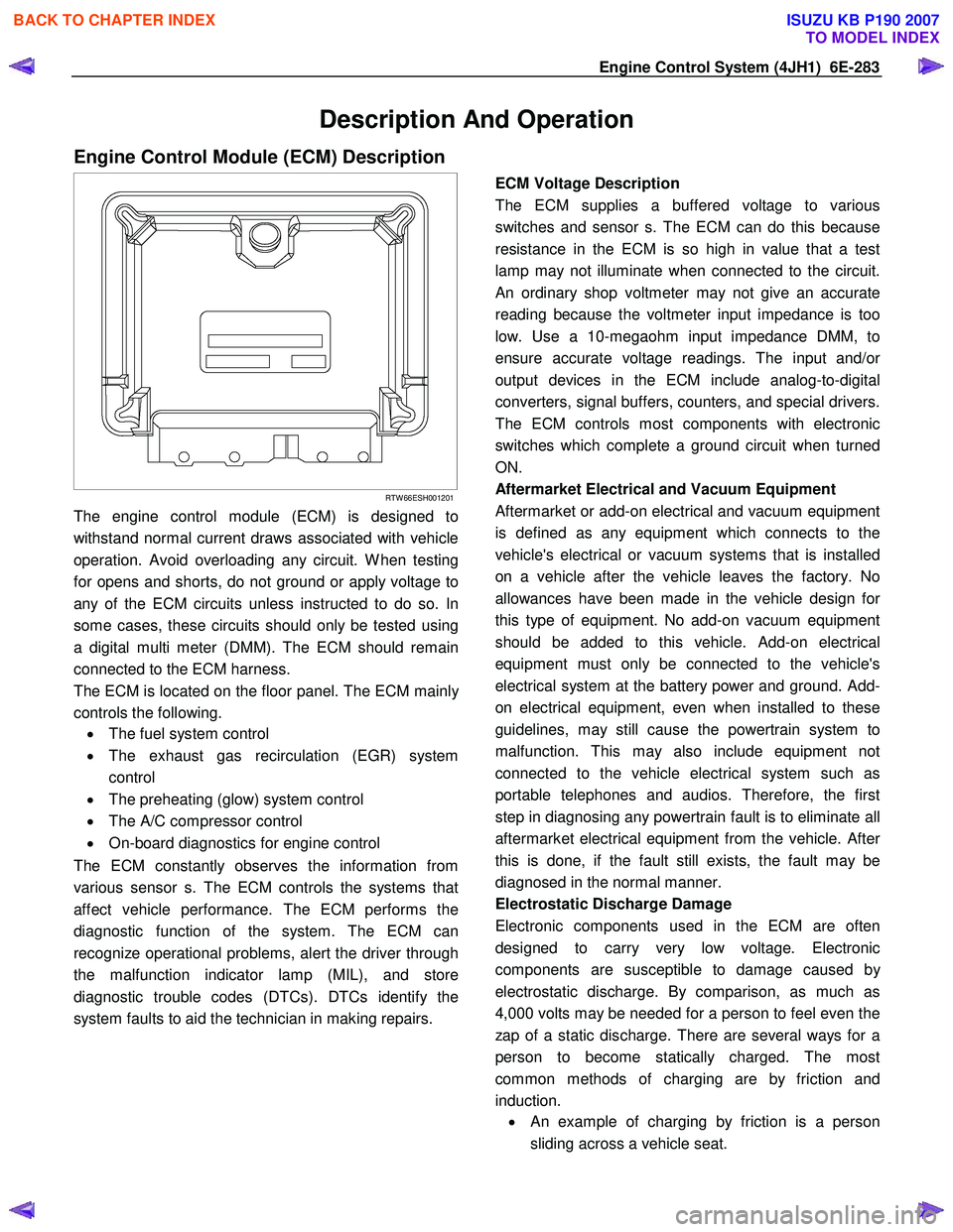
The engine control module (ECM) is designed to
withstand normal current draws associated with vehicle
operation. Avoid overloading any circuit. W hen testing
for opens and shorts, do not ground or apply voltage to
any of the ECM circuits unless instructed to do so. In
some cases, these circuits should only be tested using
a digital multi meter (DMM). The ECM should remain
connected to the ECM harness.
The ECM is located on the floor panel. The ECM mainl
y
controls the following.
• The fuel system control
• The exhaust gas recirculation (EGR) system
control
• The preheating (glow) system control
• The A/C compressor control
• On-board diagnostics for engine control
The ECM constantly observes the information from
various sensor s. The ECM controls the systems that
affect vehicle performance. The ECM performs the
diagnostic function of the system. The ECM can
recognize operational problems, alert the driver through
the malfunction indicator lamp (MIL), and store
diagnostic trouble codes (DTCs). DTCs identify the
system faults to aid the technician in making repairs.
ECM Voltage Description
The ECM supplies a buffered voltage to various
switches and sensor s. The ECM can do this because
resistance in the ECM is so high in value that a test
lamp may not illuminate when connected to the circuit.
An ordinary shop voltmeter may not give an accurate
reading because the voltmeter input impedance is too
low. Use a 10-megaohm input impedance DMM, to
ensure accurate voltage readings. The input and/o
r
output devices in the ECM include analog-to-digital
converters, signal buffers, counters, and special drivers.
The ECM controls most components with electronic
switches which complete a ground circuit when turned
ON.
Aftermarket Electrical and Vacuum Equipment
Aftermarket or add-on electrical and vacuum equipment
is defined as any equipment which connects to the
vehicle's electrical or vacuum systems that is installed
on a vehicle after the vehicle leaves the factory. No
allowances have been made in the vehicle design fo
r
this type of equipment. No add-on vacuum equipment
should be added to this vehicle. Add-on electrical
equipment must only be connected to the vehicle's
electrical system at the battery power and ground. Add-
on electrical equipment, even when installed to these
guidelines, may still cause the powertrain system to
malfunction. This may also include equipment not
connected to the vehicle electrical system such as
portable telephones and audios. Therefore, the first
step in diagnosing any powertrain fault is to eliminate all
aftermarket electrical equipment from the vehicle. Afte
r
this is done, if the fault still exists, the fault may be
diagnosed in the normal manner.
Electrostatic Discharge Damage
Electronic components used in the ECM are often
designed to carry very low voltage. Electronic
components are susceptible to damage caused b
y
electrostatic discharge. By comparison, as much as
4,000 volts may be needed for a person to feel even the
zap of a static discharge. There are several ways for a
person to become statically charged. The most
common methods of charging are by friction and
induction. •
An example of charging by friction is a person
sliding across a vehicle seat.
BACK TO CHAPTER INDEX
TO MODEL INDEX
ISUZU KB P190 2007
Page 1971 of 6020
6E-354 ENGINE CONTROL SYSTEM (4JK1/4JJ1)
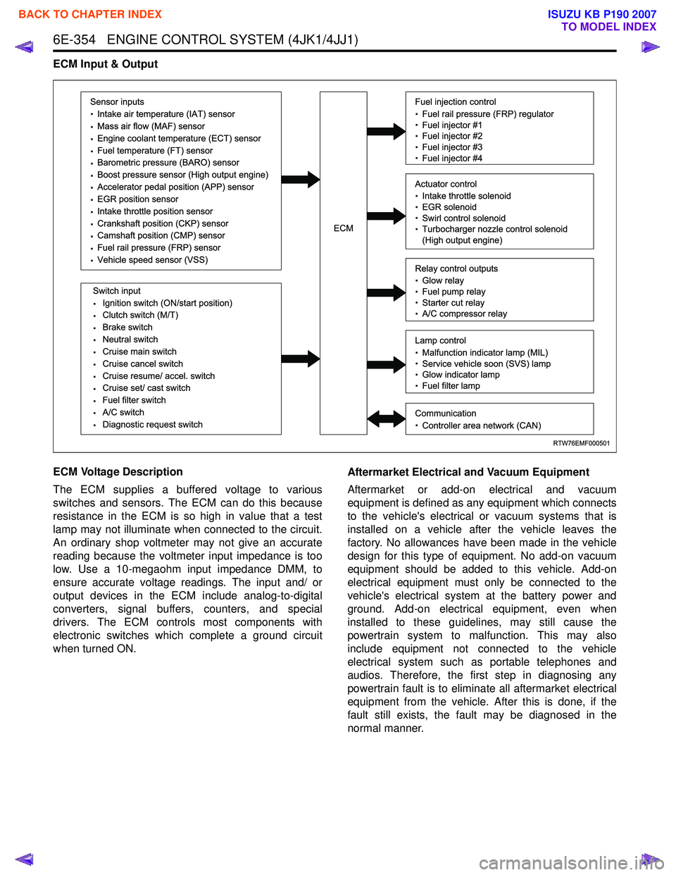
ECM Input & Output
ECM Voltage Description
The ECM supplies a buffered voltage to various
switches and sensors. The ECM can do this because
resistance in the ECM is so high in value that a test
lamp may not illuminate when connected to the circuit.
An ordinary shop voltmeter may not give an accurate
reading because the voltmeter input impedance is too
low. Use a 10-megaohm input impedance DMM, to
ensure accurate voltage readings. The input and/ or
output devices in the ECM include analog-to-digital
converters, signal buffers, counters, and special
drivers. The ECM controls most components with
electronic switches which complete a ground circuit
when turned ON. Aftermarket Electrical and Vacuum Equipment
Aftermarket or add-on electrical and vacuum
equipment is defined as any equipment which connects
to the vehicle's electrical or vacuum systems that is
installed on a vehicle after the vehicle leaves the
factory. No allowances have been made in the vehicle
design for this type of equipment. No add-on vacuum
equipment should be added to this vehicle. Add-on
electrical equipment must only be connected to the
vehicle's electrical system at the battery power and
ground. Add-on electrical equipment, even when
installed to these guidelines, may still cause the
powertrain system to malfunction. This may also
include equipment not connected to the vehicle
electrical system such as portable telephones and
audios. Therefore, the first step in diagnosing any
powertrain fault is to eliminate all aftermarket electrical
equipment from the vehicle. After this is done, if the
fault still exists, the fault may be diagnosed in the
normal manner.
RTW76EMF000501
Sensor inputs
· Intake air temperature (IAT) sensor
· Mass air flow (MAF) sensor
· Engine coolant temperature (ECT) sensor
· Fuel temperature (FT) sensor
· Barometric pressure (BARO) sensor
· Boost pressure sensor (High output engine)
· Accelerator pedal position (APP) sensor
· EGR position sensor
· Intake throttle position sensor
· Crankshaft position (CKP) sensor
· Camshaft position (CMP) sensor
· Fuel rail pressure (FRP) sensor
· Vehicle speed sensor (VSS)
Switch input
· Ignition switch (ON/start position)
· Clutch switch (M/T)
· Brake switch
· Neutral switch
· Cruise main switch
· Cruise cancel switch
· Cruise resume/ accel. switch
· Cruise set/ cast switch
· Fuel filter switch
· A/C switch
· Diagnostic request switch
Fuel injection control
· Fuel rail pressure (FRP) regulator
· Fuel injector #1
· Fuel injector #2
· Fuel injector #3
· Fuel injector #4
Relay control outputs
· Glow relay
· Fuel pump relay
· Starter cut relay
· A/C compressor relay
Lamp control
· Malfunction indicator lamp (MIL)
· Service vehicle soon (SVS) lamp
· Glow indicator lamp
· Fuel filter lamp
Communication
· Controller area network (CAN)
Actuator control
· Intake throttle solenoid
· EGR solenoid
· Swirl control solenoid
· Turbocharger nozzle control solenoid
(High output engine)ECM
BACK TO CHAPTER INDEX
TO MODEL INDEX
ISUZU KB P190 2007
Page 2161 of 6020
STARTING AND CHARGING SYSTEM 6D3-13
5. During current output tests please make sure that the
ammeter is securely connceted into the charge circuit.
6. Some battery powered timing lights can produce high transient voltages when connected or disconnected. Onl
y
disconnect or connect timing lights when the engine is
switched off.
7. Make sure the warning lamp circuit is functioning normall
y
before commencing tests.
8. Battery isolation switches must only be operated when the engine is stopped.
9. To protect the charging system when using 240 volt chargers it is recommeneded that the battery is
disconnected whilst charging.
10. Due to the very low resistance value of the stator winding it may not be possible to obtain accurate readings without
special equipment.
11. 12 volts must never be connected to the "L" terminal of the regulator as this will damage the lamp driver circuit.
12. No loads apart from the warning lamp can be connected to the "L" termainal. The "W " terminal is provided for this
purpose.
Disassembly
1. Mark the relative positions of the end housings in relation to the stator assembly to aid reassembly. Use a permanent
marking pen do not use centre punched as this can cause
misalignmnet of the housings.
2. Remove the EP regulator from the slipring end housing b
y
removing the two screws. Tilt the regulator slightly from the
plug connection until the regulator clears the housing, then
lift clear.
3. Remove the four through bolts.
4. Carefully remove the stator assembly along with the slipring end housing taking care not to put strain on the stator wires.
5. To disconnect the stator from the rectifier assembly, grasp the stator wires close to the wire loop with a pair of long
nosed pliers, heat the joint with a soldering iron, when the
point becomes plastic apply a slight twisting motion to the
wires, then pull upwards to release the wires. Remove the
stator.
This procedure opens the wire loop to release the stato
r
connections easily.
6. To remove the rectifier remove the three retaining scre
w
and the B+ terminal nut and washers.
Note: the B+ bolt and the positive heatsink retaining screw are
fitted with mica insulating washers.
These must be discarded and replaced with new washers and
heatsink compound.
BACK TO CHAPTER INDEX
TO MODEL INDEX
ISUZU KB P190 2007
Page 2218 of 6020
6E–48 ENGINE DRIVEABILITY AND EMISSIONS
GENERAL DESCRIPTION FOR ECM AND
SENSORS
Engine Control Module (ECM)
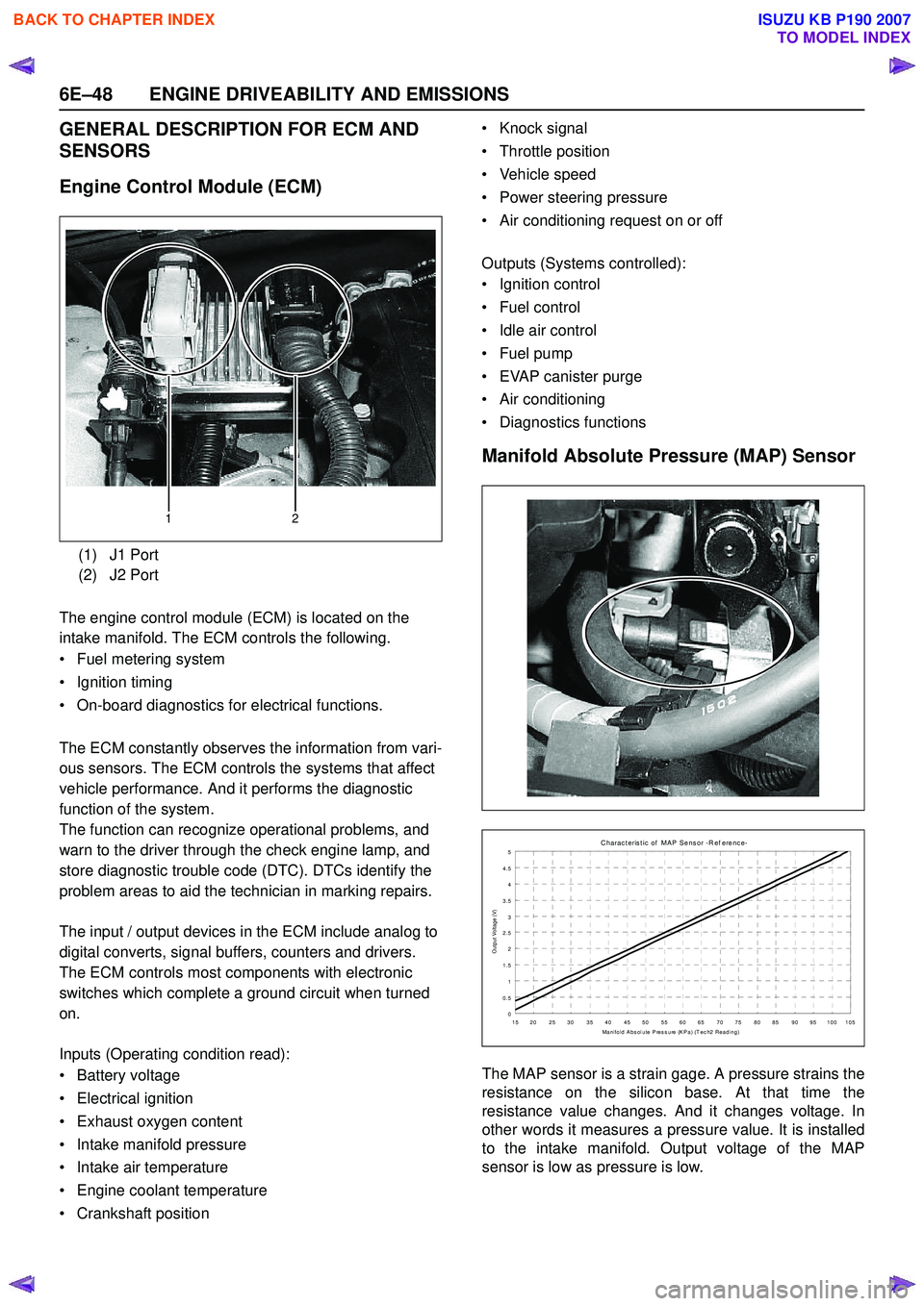
The engine control module (ECM) is located on the
intake manifold. The ECM controls the following.
• Fuel metering system
• Ignition timing
• On-board diagnostics for electrical functions.
The ECM constantly observes the information from vari-
ous sensors. The ECM controls the systems that affect
vehicle performance. And it performs the diagnostic
function of the system.
The function can recognize operational problems, and
warn to the driver through the check engine lamp, and
store diagnostic trouble code (DTC). DTCs identify the
problem areas to aid the technician in marking repairs.
The input / output devices in the ECM include analog to
digital converts, signal buffers, counters and drivers.
The ECM controls most components with electronic
switches which complete a ground circuit when turned
on.
Inputs (Operating condition read):
• Battery voltage
• Electrical ignition
• Exhaust oxygen content
• Intake manifold pressure
• Intake air temperature
• Engine coolant temperature
• Crankshaft position • Knock signal
• Throttle position
• Vehicle speed
• Power steering pressure
• Air conditioning request on or off
Outputs (Systems controlled):
• Ignition control
• Fuel control
• Idle air control
• Fuel pump
• EVAP canister purge
• Air conditioning
• Diagnostics functions
Manifold Absolute Pressure (MAP) Sensor
The MAP sensor is a strain gage. A pressure strains the
resistance on the silicon base. At that time the
resistance value changes. And it changes voltage. In
other words it measures a pressure value. It is installed
to the intake manifold. Output voltage of the MAP
sensor is low as pressure is low.
(1) J1 Port
(2) J2 Port
12
C harac t eris t ic of MAP Sens or -R ef erenc e-
0
0.5 1
1.5 2
2.5
3
3.5 4
4.5 5
15 20 25 30 35 40 45 50 55 60 65 70 75 80 85 90 95 100 105 Manifold Abs olute Press ure (KPa) (T ec h2 Reading)
Output Voltage (V)
BACK TO CHAPTER INDEX
TO MODEL INDEX
ISUZU KB P190 2007
Page 2230 of 6020
6E–60 ENGINE DRIVEABILITY AND EMISSIONS
A/C CLUTCH DIAGNOSIS
A/C Clutch Circuit Operation
A 12-volt signal is supplied to the A/C request input of
the ECM when the A/C is selected through the A/C
control switch.
The A/C compressor clutch relay is controlled through
the ECM. This allows the ECM to modify the idle air
control position prior to the A/C clutch engagement for
better idle quality. If the engine operating conditions are
within their specified calibrated acceptable ranges, the
ECM will enable the A/C compressor relay. This is done
by providing a ground path for the A/C relay coil within
the ECM. When the A/C compressor relay is enabled,
battery voltage is supplied to the compressor relay is
enabled, battery voltage is supplied to the compressor
clutch coil.
The ECM will enable the A/C compressor clutch
whenever the engine is running and the A/C has been
requested. The ECM will not enable the A/C
compressor clutch if any of the following conditions are
met:
• The engine speed is greater than 6000 RPM.
• The ECT is greater than 122°C (251°F).
• The throttle is more than 95% open.
A/C Clutch Circuit Purpose
The A/C compressor operation is controlled by the
engine control module (ECM) for the following reasons:
• It improves idle quality during compressor clutch engagement.
• It improves wide open throttle (WOT) performance.
• It provides A/C compressor protection from operation with incorrect refrigerant pressures.
The A/C electrical system consists of the following
components:
• The A/C control switch.
• The A/C refrigerant pressure switches.
• The A/C compressor clutch.
• The A/C compressor clutch relay.
•The ECM.
A/C Request Signal
This signal tells the ECM when the A/C mode is
selected at the A/C control switch. The ECM uses this
input to adjust the idle speed before turning on the A/C
clutch. The A/C compressor will be inoperative if this
signal is not available to the ECM.
Refer to A/C Clutch Circuit Diagnosis for A/C wiring
diagrams and diagnosis for the A/C electrical system.
BACK TO CHAPTER INDEX
TO MODEL INDEX
ISUZU KB P190 2007