2007 ISUZU KB P190 lights
[x] Cancel search: lightsPage 1201 of 6020
Engine Control System (4JH1) 6E-167
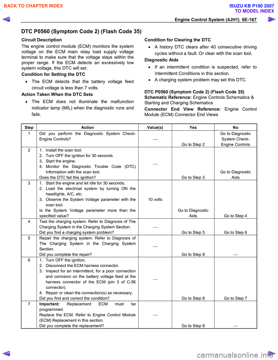
DTC P0560 (Symptom Code 2) (Flash Code 35)
Circuit Description
The engine control module (ECM) monitors the system
voltage on the ECM main relay load supply voltage
terminal to make sure that the voltage stays within the
proper range. If the ECM detects an excessively lo
w
system voltage, this DTC will set.
Condition for Setting the DTC
• The ECM detects that the battery voltage feed
circuit voltage is less than 7 volts.
Action Taken When the DTC Sets
• The ECM does not illuminate the malfunction
indicator lamp (MIL) when the diagnostic runs and
fails.
Condition for Clearing the DTC
• A history DTC clears after 40 consecutive driving
cycles without a fault. Or clear with the scan tool.
Diagnostic Aids
• If an intermittent condition is suspected, refer to
Intermittent Conditions in this section.
• A charging system problem may set this DTC.
DTC P0560 (Symptom Code 2) (Flash Code 35)
Schematic Reference: Engine Controls Schematics &
Starting and Charging Schematics
Connector End View Reference: Engine Control
Module (ECM) Connector End Views
Step Action Value(s) Yes No
1 Did you perform the Diagnostic System Check-
Engine Controls?
Go to Step 2 Go to Diagnostic
System Check-
Engine Controls
2 1. Install the scan tool. 2. Turn OFF the ignition for 30 seconds.
3. Start the engine.
4. Monitor the Diagnostic Trouble Code (DTC) Information with the scan tool.
Does the DTC fail this ignition?
Go to Step 3 Go to Diagnostic
Aids
3 1. Start the engine and let idle for 30 seconds. 2. Load the electrical system by turning ON the headlights, A/C, etc.
3. Observe the System Voltage parameter with the scan tool.
Is the System Voltage parameter more than the
specified value? 10 volts
Go to Diagnostic Aids Go to Step 4
4 Test the charging system. Refer to Diagnosis of The Charging System in the Charging System Section.
Did you find a charging system problem?
Go to Step 5 Go to Step 6
5 Repair the charging system. Refer to Diagnosis of The Charging System in the Charging System
Section.
Did you complete the repair?
Go to Step 8
6 1. Turn OFF the ignition.
2. Disconnect the ECM harness connector.
3. Inspect for an intermittent, for a poor connection and corrosion on the battery voltage feed at the
harness connector of the ECM (pin 3 of C-56
connector).
4. Repair or clean the connection(s) as necessary.
Did you find and correct the condition?
Go to Step 8 Go to Step 7
7 Important: Replacement ECM must be
programmed.
Replace the ECM. Refer to Engine Control Module
(ECM) Replacement in this section.
Did you complete the replacement?
Go to Step 8
BACK TO CHAPTER INDEX
TO MODEL INDEX
ISUZU KB P190 2007
Page 1202 of 6020
6E-168 Engine Control System (4JH1)
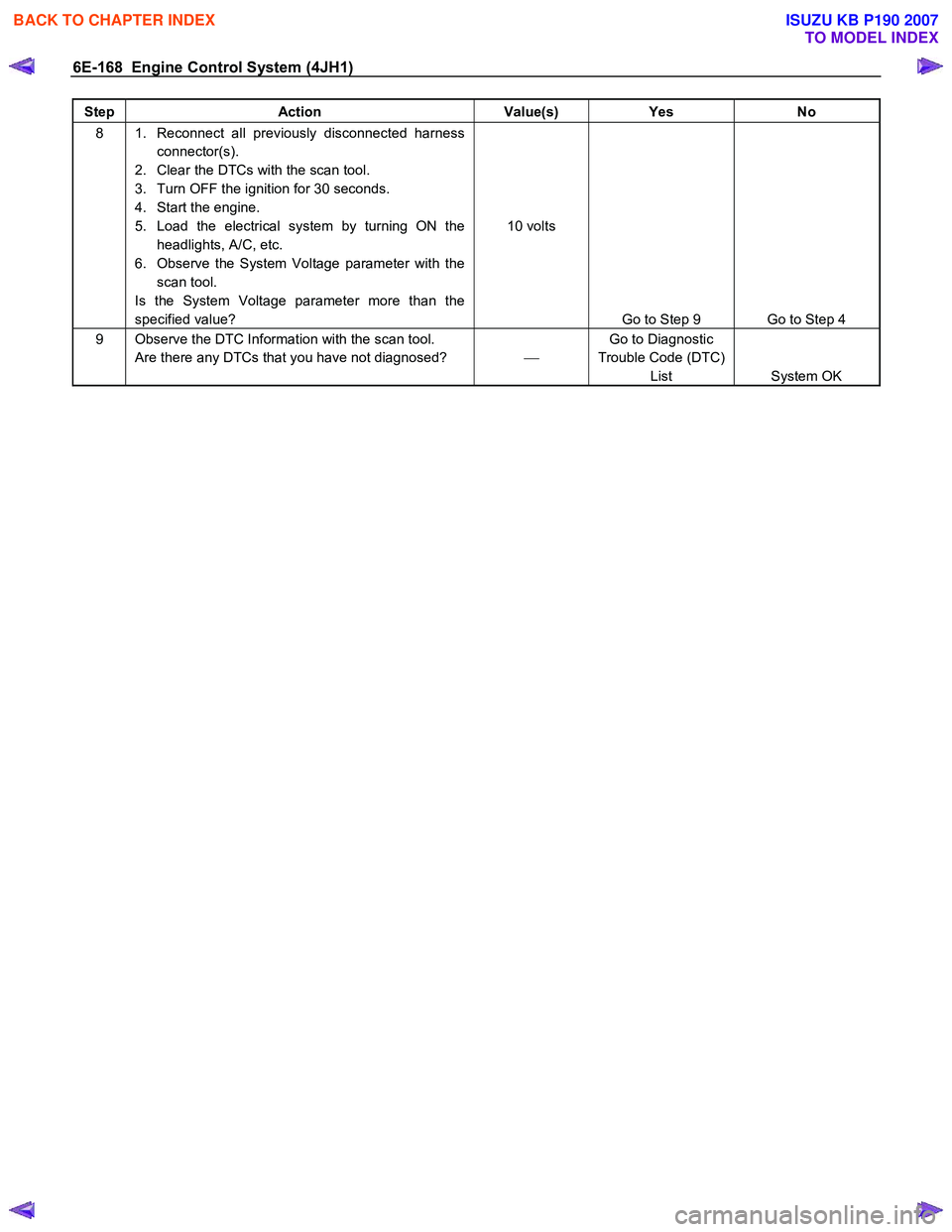
Step Action Value(s) Yes No
8 1. Reconnect all previously disconnected harness
connector(s).
2. Clear the DTCs with the scan tool.
3. Turn OFF the ignition for 30 seconds.
4. Start the engine.
5. Load the electrical system by turning ON the headlights, A/C, etc.
6. Observe the System Voltage parameter with the scan tool.
Is the System Voltage parameter more than the
specified value? 10 volts
Go to Step 9 Go to Step 4
9 Observe the DTC Information with the scan tool. Are there any DTCs that you have not diagnosed? Go to Diagnostic
Trouble Code (DTC) List System OK
BACK TO CHAPTER INDEX
TO MODEL INDEX
ISUZU KB P190 2007
Page 1215 of 6020
Engine Control System (4JH1) 6E-181
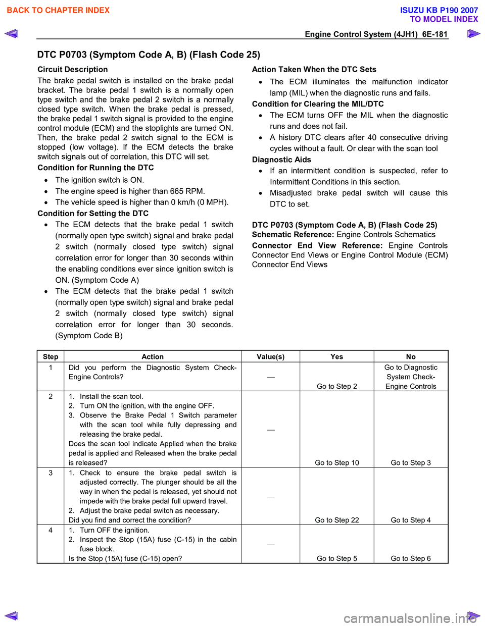
DTC P0703 (Symptom Code A, B) (Flash Code 25)
Circuit Description
The brake pedal switch is installed on the brake pedal
bracket. The brake pedal 1 switch is a normally open
type switch and the brake pedal 2 switch is a normally
closed type switch. W hen the brake pedal is pressed,
the brake pedal 1 switch signal is provided to the engine
control module (ECM) and the stoplights are turned ON.
Then, the brake pedal 2 switch signal to the ECM is
stopped (low voltage). If the ECM detects the brake
switch signals out of correlation, this DTC will set.
Condition for Running the DTC
• The ignition switch is ON.
• The engine speed is higher than 665 RPM.
• The vehicle speed is higher than 0 km/h (0 MPH).
Condition for Setting the DTC • The ECM detects that the brake pedal 1 switch
(normally open type switch) signal and brake pedal
2 switch (normally closed type switch) signal
correlation error for longer than 30 seconds within
the enabling conditions ever since ignition switch is
ON. (Symptom Code A)
• The ECM detects that the brake pedal 1 switch
(normally open type switch) signal and brake pedal
2 switch (normally closed type switch) signal
correlation error for longer than 30 seconds.
(Symptom Code B)
Action Taken When the DTC Sets
• The ECM illuminates the malfunction indicato
r
lamp (MIL) when the diagnostic runs and fails.
Condition for Clearing the MIL/DTC • The ECM turns OFF the MIL when the diagnostic
runs and does not fail.
• A history DTC clears after 40 consecutive driving
cycles without a fault. Or clear with the scan tool
Diagnostic Aids • If an intermittent condition is suspected, refer to
Intermittent Conditions in this section.
• Misadjusted brake pedal switch will cause this
DTC to set.
DTC P0703 (Symptom Code A, B) (Flash Code 25)
Schematic Reference: Engine Controls Schematics
Connector End View Reference: Engine Controls
Connector End Views or Engine Control Module (ECM)
Connector End Views
Step Action Value(s) Yes No
1 Did you perform the Diagnostic System Check-
Engine Controls?
Go to Step 2 Go to Diagnostic
System Check-
Engine Controls
2 1. Install the scan tool. 2. Turn ON the ignition, with the engine OFF.
3. Observe the Brake Pedal 1 Switch parameter with the scan tool while fully depressing and
releasing the brake pedal.
Does the scan tool indicate Applied when the brake
pedal is applied and Released when the brake pedal
is released?
Go to Step 10 Go to Step 3
3 1. Check to ensure the brake pedal switch is adjusted correctly. The plunger should be all the
way in when the pedal is released, yet should not
impede with the brake pedal full upward travel.
2. Adjust the brake pedal switch as necessary.
Did you find and correct the condition?
Go to Step 22 Go to Step 4
4 1. Turn OFF the ignition. 2. Inspect the Stop (15A) fuse (C-15) in the cabin fuse block.
Is the Stop (15A) fuse (C-15) open?
Go to Step 5 Go to Step 6
BACK TO CHAPTER INDEX
TO MODEL INDEX
ISUZU KB P190 2007
Page 1231 of 6020
Engine Control System (4JH1) 6E-197
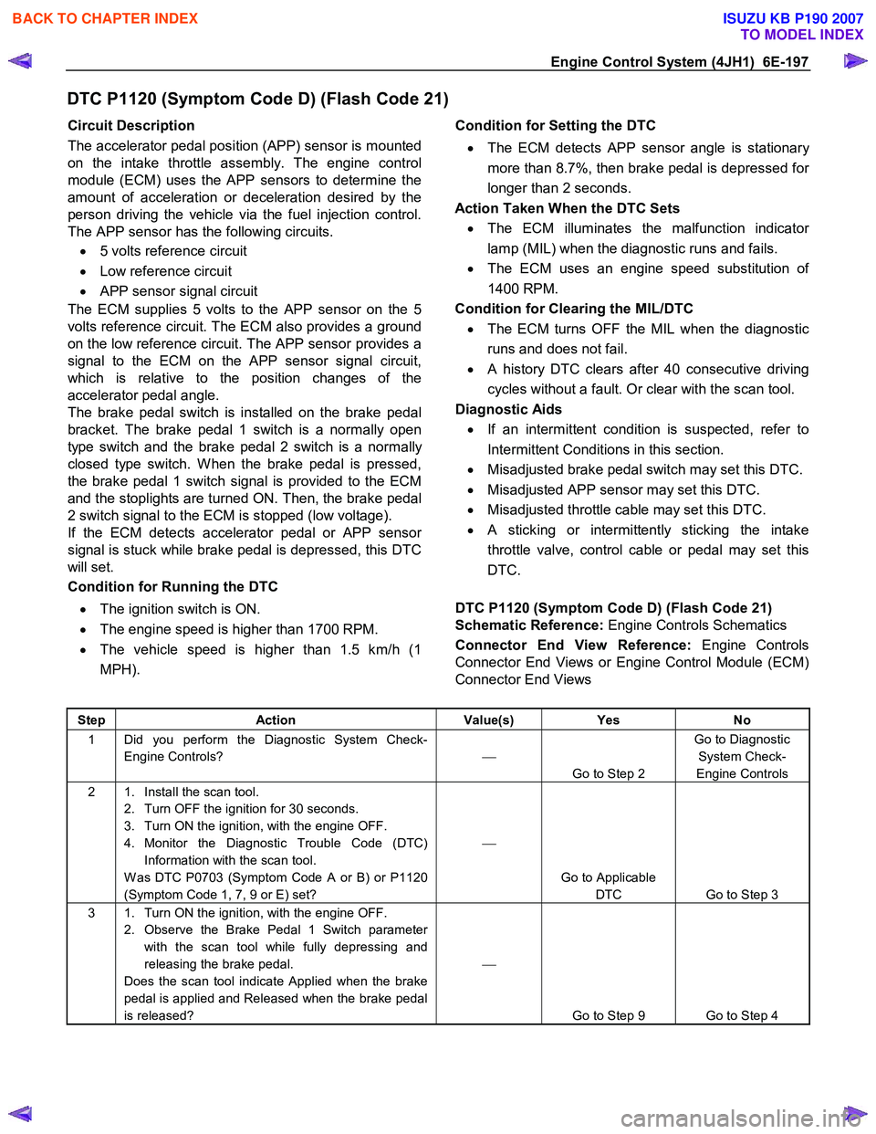
DTC P1120 (Symptom Code D) (Flash Code 21)
Circuit Description
The accelerator pedal position (APP) sensor is mounted
on the intake throttle assembly. The engine control
module (ECM) uses the APP sensors to determine the
amount of acceleration or deceleration desired by the
person driving the vehicle via the fuel injection control.
The APP sensor has the following circuits.
• 5 volts reference circuit
• Low reference circuit
• APP sensor signal circuit
The ECM supplies 5 volts to the APP sensor on the 5
volts reference circuit. The ECM also provides a ground
on the low reference circuit. The APP sensor provides a
signal to the ECM on the APP sensor signal circuit,
which is relative to the position changes of the
accelerator pedal angle.
The brake pedal switch is installed on the brake pedal
bracket. The brake pedal 1 switch is a normally open
type switch and the brake pedal 2 switch is a normally
closed type switch. W hen the brake pedal is pressed,
the brake pedal 1 switch signal is provided to the ECM
and the stoplights are turned ON. Then, the brake pedal
2 switch signal to the ECM is stopped (low voltage).
If the ECM detects accelerator pedal or APP senso
r
signal is stuck while brake pedal is depressed, this DTC
will set.
Condition for Running the DTC
• The ignition switch is ON.
• The engine speed is higher than 1700 RPM.
• The vehicle speed is higher than 1.5 km/h (1
MPH).
Condition for Setting the DTC
• The ECM detects APP sensor angle is stationar
y
more than 8.7%, then brake pedal is depressed fo
r
longer than 2 seconds.
Action Taken When the DTC Sets • The ECM illuminates the malfunction indicato
r
lamp (MIL) when the diagnostic runs and fails.
• The ECM uses an engine speed substitution o
f
1400 RPM.
Condition for Clearing the MIL/DTC • The ECM turns OFF the MIL when the diagnostic
runs and does not fail.
• A history DTC clears after 40 consecutive driving
cycles without a fault. Or clear with the scan tool.
Diagnostic Aids • If an intermittent condition is suspected, refer to
Intermittent Conditions in this section.
• Misadjusted brake pedal switch may set this DTC.
• Misadjusted APP sensor may set this DTC.
• Misadjusted throttle cable may set this DTC.
• A sticking or intermittently sticking the intake
throttle valve, control cable or pedal may set this
DTC.
DTC P1120 (Symptom Code D) (Flash Code 21)
Schematic Reference: Engine Controls Schematics
Connector End View Reference: Engine Controls
Connector End Views or Engine Control Module (ECM)
Connector End Views
Step Action Value(s) Yes No
1 Did you perform the Diagnostic System Check-
Engine Controls?
Go to Step 2 Go to Diagnostic
System Check-
Engine Controls
2 1. Install the scan tool. 2. Turn OFF the ignition for 30 seconds.
3. Turn ON the ignition, with the engine OFF.
4. Monitor the Diagnostic Trouble Code (DTC) Information with the scan tool.
W as DTC P0703 (Symptom Code A or B) or P1120
(Symptom Code 1, 7, 9 or E) set?
Go to Applicable DTC Go to Step 3
3 1. Turn ON the ignition, with the engine OFF. 2. Observe the Brake Pedal 1 Switch parameter with the scan tool while fully depressing and
releasing the brake pedal.
Does the scan tool indicate Applied when the brake
pedal is applied and Released when the brake pedal
is released?
Go to Step 9 Go to Step 4
BACK TO CHAPTER INDEX
TO MODEL INDEX
ISUZU KB P190 2007
Page 1289 of 6020
Engine Control System (4JH1) 6E-255
Symptoms – Engine Controls
Symptoms – Engine Controls
Important Preliminary Inspections Before Starting
Perform Diagnostic System Check – Engine Controls
before using the symptom tables, and verify that all o
f
the following are true:
• The engine control module (ECM) and malfunction
indicator lamp (MIL) are operating correctly.
• There are no diagnostic trouble codes (DTCs)
stored, or a DTC exists but without the MIL.
• The scan tool data is within the normal operating
range. Refer to scan tool Data List in this section.
• Verify the customer concern and locate the correct
symptom in the table of contents. Inspect the items
indicated under that symptom.
Visual and Physical Inspection
Several of the symptom procedures ask for careful
visual and physical inspection. This step is extremel
y
important. The visual and physical inspection can lead
to correcting a problem without further inspections, and
can save valuable time. Ensure that:
• The ECM grounds are clean, tight, and in thei
r
proper location.
• The vacuum hoses are not split or kinked, and
properly connected. Inspect thoroughly for an
y
type of leak or restriction.
• The mass air flow (MAF) sensor is properl
y
installed. The arrows on the plastic portion of the
sensor must point toward the engine.
• The air intake ducts are not collapsed or damaged.
• There are no leaks at the MAF sensor, an
y
connections or intake manifold sealing surfaces.
• The engine harness wiring and terminals are
properly connected and are not pinched or cut.
Intermittent
Important:
Inspect for improper installation of electrical
components if an intermittent condition exists. Inspect
for aftermarket add-on electrical equipment devices,
lights, and cellular phones. Verify that no aftermarket
equipment is connected to the keyword 2000 serial data
circuit. If you cannot locate an intermittent condition, a
cellular phone communication signal may cause the
condition.
Important:
The problem may or may not turn ON the MIL or store a
DTC.
Faulty electrical connections or wiring cause most
intermittent problems. Perform a careful visual and
physical inspection of the suspect connectors for the
following conditions:
• Improperly mated connector halves
• Terminals that are not seated
• Terminals that are damaged or improperly formed
Reform or replace connector terminals in the problem
circuit in order to ensure proper contact tension.
Remove the terminal from the connector body in orde
r
to inspect for poor terminal wire connection.
Road test the vehicle with the DMM connected to the
suspected circuit. An abnormal reading that occurs
when the malfunction occurs is a good indication that
there is a malfunction in the circuit being monitored.
Use the scan tool in order to help detect intermittent
conditions. Useful features of the scan tool include the
following:
• Trigger the Snapshot feature in order to capture
and store engine parameters when the malfunction
occurs. Review this stored information in order to
see the specific running conditions that caused the
malfunction.
• Use the Plot Function on the scan tool in order to
plot selected data parameters. Review this stored
information to aid in locating an intermittent
problem. Refer to the scan tool Users Guide fo
r
more information.
Important:
If the intermittent condition exists as a start and then
stall, test for DTCs relating to the vehicle theft deterrent
system. Test for improper installation of electrical
options such as lights, cellular phones, etc.
Any of the following may cause an intermittent MIL with
no stored DTC:
• The ECM grounds are loose or dirty. Refer to
Engine Controls Schematics.
• The MIL circuit intermittently shorted to ground.
• Electrical system interference caused by a
malfunctioning relay, ECM driven solenoid, o
r
switch. The electrical component can cause a
sharp electrical surge. Normally, the problem will
occur when the malfunctioning component is
operating.
• There is an open diode across the A/C
compressor clutch or any other open diodes.
BACK TO CHAPTER INDEX
TO MODEL INDEX
ISUZU KB P190 2007
Page 1292 of 6020
6E-258 Engine Control System (4JH1)
Checks Action
Electromagnetic Interference (EMI)
and Electrical Noise Some electrical components/circuits are sensitive to EMI or other types of electrical
noise. Inspect for the following conditions:
• A misrouted harness that is too close to high voltage/high current devices such as
injection components, motors, generator etc. These components may induce
electrical noise on a circuit that could interfere with normal circuit operation.
• Electrical system interference caused by a malfunctioning relay, or the engine control
module (ECM) driven solenoid or switch. These conditions can cause a sharp
electrical surge. Normally, the problem will occur when the malfunctioning
component is operating.
• Improper installation of non-factory or aftermarket add on accessories such as lights,
2-way radios, amplifiers, electric motors, remote starters, alarm systems, cell
phones, etc. These accessories may lead to an emission related failure while in use,
but do not fail when the accessories are not in use.
• Test for an open diode across the A/C compressor clutch and for other open diodes.
Some relays may contain a clamping diode.
• Test the generator for a bad rectifier bridge that may be allowing AC noise into the
electrical system.
Incorrect ECM Programming • There are only a few situations where reprogramming a ECM is appropriate:
Important:
DO NOT reprogram the ECM with the SAME software/calibration files that are already
present in the ECM. This is not an effective repair for any type of driveability problem. - A ECM from another vehicle is installed.
- Revised software/calibration files have been released for this vehicle.
• Verify that the ECM contains the correct software/calibration. If incorrect
programming is found, reprogram the ECM with the most current
software/calibration.
Duplicating Failure Conditions • If none of the previous tests are successful, attempt to duplicate and/or capture the
failure conditions.
• An alternate method is to drive the vehicle with the DMM connected to a suspected
circuit. An abnormal reading on the DMM when the problem occurs, may help you
locate the problem.
scan tool Snapshot The scan tool can be set up to take a Snapshot of the parameters available via serial
data. The Snapshot function records live data over a period of time. The recorded data
can be played back and analyzed. The scan tool can also graph parameters singly or
in combinations of parameters for comparison. The Snapshot can be triggered
manually at the time the symptom is noticed, or set up in advance to trigger when a
DTC sets.
An abnormal value captured in the recorded data may point to a system or component
that needs to be investigated further.
Refer to the scan tool user instructions for more information on the Snapshot function.
Hard Start
Checks Action
DEFINITION:The engine cranks OK, but does not start for a long time. The engine does eventually run, or may start but
immediately dies.
Preliminary Checks •
Diagnostic System Check - Engine Controls.
• Ensure the driver is using the correct starting procedure.
• Inspect the engine control module (ECM) and fuel injection pump control unit (PCU)
grounds for being clean, tight, and in their proper locations.
• Inspect that the harness connectors are correctly connected.
• Inspect the fuel type and quality.
• Inspect the scan tool Data List in this section.
• Inspect the Service Bulletins for ECM software updates.
BACK TO CHAPTER INDEX
TO MODEL INDEX
ISUZU KB P190 2007
Page 1310 of 6020
6E-276 Engine Control System (4JH1)
1. Connect the scan tool to the vehicle DLC, with theengine and the scan tool OFF.
2. Turn ON the scan tool.
3. Select Diagnostic > appropriate vehicle identification > Powertrain > 4JH1-TC >
Programming > Program VIN.
4. Input correct VIN reading from stamped VIN o
r
affixed VIN plate on the vehicle.
Select Lock ECU and lock the programmed VIN.
Service Programming System (SPS)
Description
The service programming system (SPS) allows a
technician to program a control module through the data
link connector (DLC). The information transfer circuit that
is used at the DLC is the same serial data circuit used be
the scan tool for retrieving diagnostic trouble codes
(DTCs), displaying data, clearing DTCs etc. This
procedure offers the ability to install software/calibrations
matched to a particular vehicle.
Most control modules have two types of memory. The
software/calibrations reside in the flash memory. The two
types of memory are listed below: • Electrically Erasable Programmable Read Onl
y
Memory (EEPROM).
This type of memory allows selected portions o
f
memory to be programmed while other portions
remain unchanged.
Certain learned values reside in the EEPROM, such as:
- The vehicle identification number (VIN)
- The software/calibrations identification numbers
- The control module security information
• Flash Read Only Memory-Flash Memory
Flash memory has increased memory storage capacity. During programming, all information within
this type of memory is erased, and then replaced
with entirely new information.
Service Programming Methods
The two methods of programming an engine control
module (ECM) are listed below: • Remote Programming
• Pass Thru Programming
For information on programming an ECM using one o
f
the methods listed above, refer to Service Programming
System (SPS) (Remote Procedure) or Service
Programming System (SPS) (Pass-Thru Procedure).
Before Programming a Control Module
Important:
DO NOT program an existing ECM with the identical
software/calibration package. This procedure is not a
short cut to correct the driveability condition. This is an
ineffective repair. An ECM should only be programmed
when the following occurs: • W hen a service procedure instructs you to replace
the ECM. W hen the ECM from another vehicle is
installed, VIN must be changed. And change
vehicle information as necessary such as type o
f
transmission.
• An updated software/calibrations is released.
Ensure that the following conditions are met before
programming an ECM: • The scan tool PCMCIA card is programmed with
the latest software.
• The TIS 2000 is installed with the latest software.
• The hardware key is plugged into the compute
r
port.
• Vehicle system voltage:
- There are no charging system concerns. All charging system concerns must be repaired
before programming the ECM.
- The battery voltage is greater than 12 volts bu
t
less than 16 volts. The battery must be fully
charged before programming the ECM.
-
A battery charger is NOT connected to the
vehicles battery. Incorrect system voltage o
r
voltage fluctuations from a battery charger may
cause programming failure or ECM damage.
- Turn OFF or disable any system that may put a load on the vehicles battery. Turn OFF o
r
disable systems such as:
◊ Heating, ventilation, and air conditioning
(HVAC) systems
◊ Headlights
◊ Room lights
◊ Accessory equipment
• The ignition switch is in the proper position. The
scan tool prompts you to turn ON the ignition, with
the engine OFF. DO NOT change the position o
f
the ignition switch during the programming
procedure unless instructed to do so.
• All tool connections are secure:
- The RS-232 cable
- The connection at the DLC
- The voltage supply circuits
BACK TO CHAPTER INDEX
TO MODEL INDEX
ISUZU KB P190 2007
Page 1522 of 6020
6A-162 ENGINE MECHANICAL (4JK1/4JJ1)
Removal
1. Remove the oil pressure SW .
2. Remove the nipple; oil gallery.
3. Remove the nipple; oil pressure warning SW and gasket.
Inspection
Check the continuity between the switch terminal and
the body grounding in a no-load condition.
If there is no connectivity, replace with normal parts.
LNW 21HSH003301
Circuit check
1. Turn the starter switch to ON.
2. Disconnect the oil pressure switch connector, and confirm that the oil pressure-warning lamp lights
when the connector on the harness side is
grounded.
If the warning lamp does not light up, check the circuit between the meter and the oil pressure
switch, and repair the disconnected locations.
LNW 21HSH003401
Installation
1. Install the nipple; oil gallery, oil pressure warning
SW and gasket.
Tightening torque: 25 N ⋅
⋅⋅
⋅
m (2.5 kg ⋅
⋅⋅
⋅
m/18 lb ft)
2. Install the Nipple. Tightening torque: 15 N ⋅
⋅⋅
⋅
m (1.5 kg ⋅
⋅⋅
⋅
m/11 lb ft)
3. Install the oil pressure SW . Tightening torque: 15 N ⋅
⋅⋅
⋅
m (1.5 kg ⋅
⋅⋅
⋅
m/11 lb ft)
BACK TO CHAPTER INDEX
TO MODEL INDEX
ISUZU KB P190 2007