Page 2032 of 6020
6A-18 ENGINE MECHANICAL (C24SE)
OPERATIONS ON ENGINE AGGREGATES
Engine Damping Blocks (Engine Without
Transmission)
Removal
1. Remove bonnet.
2. Remove radiator.
3. Remove air inlet hose.
4. Remove power steering pump drive belt and power steering pump from engine.
5. Remove all cable connections, hoses and lines from
engine.
6. Remove accelerator cable from inlet pipe.
7. Remove exhaust pipe from manifold.
8. Remove lower nine bolts and transmission from engine
block.
9. Remove clutch slave cylinder and allow to hang free.
10. Remove starter from engine block.
11. Remove upper bolts of left and right engine mounting
from damping blocks.
12. Raise engine slightly.
13. Remove lower bolts of left and right damping blocks.
14. Remove damping blocks.
BACK TO CHAPTER INDEX
TO MODEL INDEX
ISUZU KB P190 2007
Page 2034 of 6020
6A-20 ENGINE MECHANICAL (C24SE)
6. Install power steering pump and V-belt.
Adjust
Adjust power steering pump V-belt tension according to the
corresponding operation.
Installation
7. Install radiator according to the corresponding operation.
8. Install air inlet hose.
9. Install all electrical cable connections, hoses and lines to engine.
10. Install accelerator cable from inlet pipe.
11. Install bonnet.
Inspection
1. Check engine oil level.
2. Fill up cooling system and bleed according to the corresponding operation.
BACK TO CHAPTER INDEX
TO MODEL INDEX
ISUZU KB P190 2007
Page 2664 of 6020
Engine Mechanical – V6 Page 6A1–185
Remove
1 Remove the skid plate.
2 Drain the radiator coolant, refer to 6B1 Engine Cooling – V6.
3 Disconnect the battery negative and positive terminal, refer to 8A Electrical Body & Chassis.
4 Remove the battery from the vehicle.
5 Depressurise the fuel system pressure, refer to 6C Fuel System – V6.
6 Make alignment marks on the bonnet and hinges in order to return the bonnet to the exact original position.
7 Remove the bonnet, refer to 2B Sheet Metal.
8 Remove the rubber hose (2) and air duct (1).
Figure 6A1 – 317
9 Disconnect the barometric sensor connector (1).
Figure 6A1 – 318
BACK TO CHAPTER INDEX
TO MODEL INDEX
ISUZU KB P190 2007
Page 3017 of 6020
Engine Mechanical – V6 Page 6A1–240
Page 6A1–240
Remove
1 Remove the skid plate.
2 Drain the radiator coolant, refer to Section 6B1 Engine Cooling – V6.
3 Disconnect the battery negative and positive terminal, refer to Section 8A Electrical Body & Chassis.
4 Remove the battery from the vehicle.
5 Depressurise the fuel sy stem pressure, refer to Section 6C Fuel System – V6 .
6 Make alignment marks on the bonnet and hinges in order to return the bonnet to the exact original position.
7 Remove the bonnet, refer to Section 2B Sheet Metal.
8 Remove the rubber hose (2) and air duct (1).
Figure 6A1 – 407
9 Disconnect the barometric sensor connector (1).
Figure 6A1 – 408
BACK TO CHAPTER INDEX
TO MODEL INDEX
ISUZU KB P190 2007
Page 3528 of 6020

Engine Management – V6 – Service Operations Page 6C1-3–4
1 General Information
1.1 General Description
This Section describes the correct service procedures to repair and test components of the V6 engine management
system. Emphasis is placed on the proper procedures and repair of components related to this specific system.
For component description, operation and location, refer to 6C1-1 Engine Management – V6 – General Information.
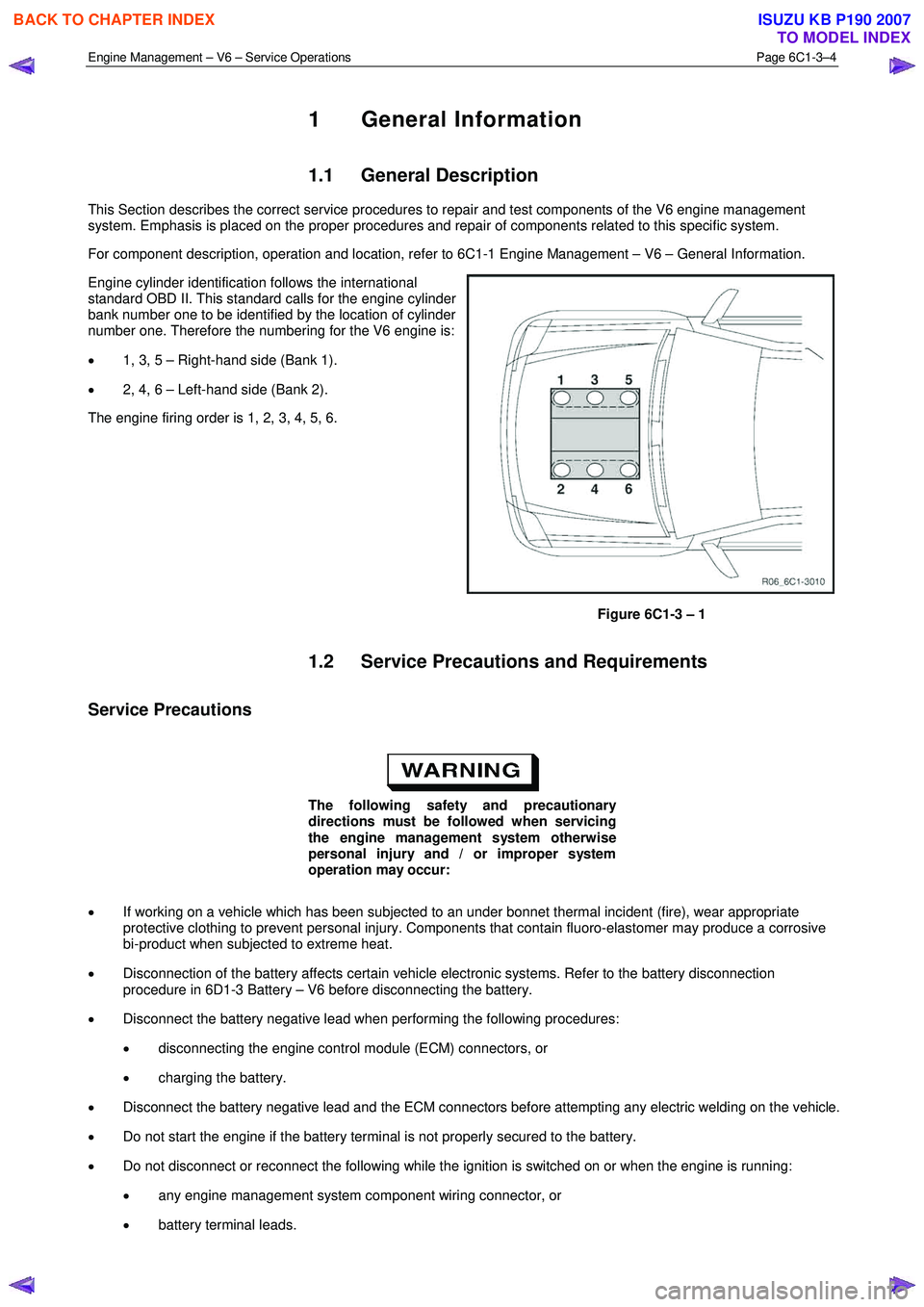
Engine cylinder identification follows the international
standard OBD II. This standard calls for the engine cylinder
bank number one to be identified by the location of cylinder
number one. Therefore the numbering for the V6 engine is:
• 1, 3, 5 – Right-hand side (Bank 1).
• 2, 4, 6 – Left-hand side (Bank 2).
The engine firing order is 1, 2, 3, 4, 5, 6.
Figure 6C1-3 – 1
1.2 Service Precautions and Requirements
Service Precautions
The following safety and precautionary
directions must be followed when servicing
the engine management system otherwise
personal injury and / or improper system
operation may occur:
• If working on a vehicle which has been subjected to an under bonnet thermal incident (fire), wear appropriate
protective clothing to prevent personal injury. Components that contain fluoro-elastomer may produce a corrosive
bi-product when subjected to extreme heat.
• Disconnection of the battery affects certain vehicle electronic systems. Refer to the battery disconnection
procedure in 6D1-3 Battery – V6 before disconnecting the battery.
• Disconnect the battery negative lead when performing the following procedures:
• disconnecting the engine control module (ECM) connectors, or
• charging the battery.
• Disconnect the battery negative lead and the ECM connectors before attempting any electric welding on the vehicle.
• Do not start the engine if the battery terminal is not properly secured to the battery.
• Do not disconnect or reconnect the following while the ignition is switched on or when the engine is running:
• any engine management system component wiring connector, or
• battery terminal leads.
BACK TO CHAPTER INDEX
TO MODEL INDEX
ISUZU KB P190 2007
Page 5104 of 6020

8A-166 ELECTRICAL-BODY AND CHASSIS
LIGHTING SYSTEM
REMOVAL AND INSTALLATION
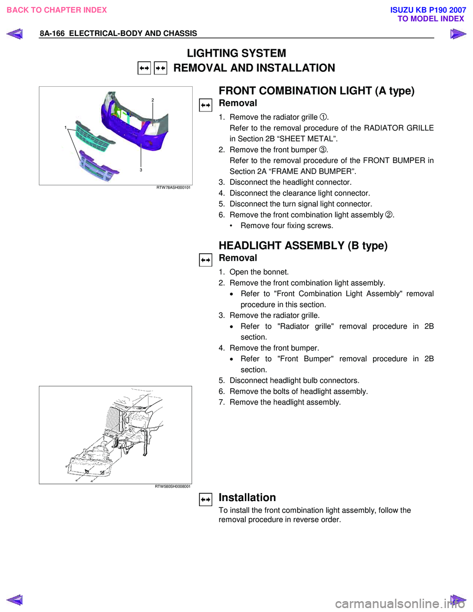
3 2
1
RTW 78ASH000101
FRONT COMBINATION LIGHT (A type)
Removal
1. Remove the radiator grille 1.
Refer to the removal procedure of the RADIATOR GRILLE
in Section 2B “SHEET METAL”.
2. Remove the front bumper
3.
Refer to the removal procedure of the FRONT BUMPER in
Section 2A “FRAME AND BUMPER”.
3. Disconnect the headlight connector.
4. Disconnect the clearance light connector.
5. Disconnect the turn signal light connector.
6. Remove the front combination light assembly
2.
• Remove four fixing screws.
HEADLIGHT ASSEMBLY (B type)
Removal
1. Open the bonnet.
2. Remove the front combination light assembly. • Refer to "Front Combination Light Assembly" removal
procedure in this section.
3. Remove the radiator grille. • Refer to "Radiator grille" removal procedure in 2B
section.
4. Remove the front bumper. • Refer to "Front Bumper" removal procedure in 2B
section.
5. Disconnect headlight bulb connectors.
RTW 580SH0008001
6. Remove the bolts of headlight assembly. 7. Remove the headlight assembly.
Installation
To install the front combination light assembly, follow the
removal procedure in reverse order.
BACK TO CHAPTER INDEX TO MODEL INDEXISUZU KB P190 2007
Page 5106 of 6020
8A-168 ELECTRICAL-BODY AND CHASSIS
HALOGEN HEADLIGHT BULB (B type)
Removal
1. Open the bonnet.
2. Disconnect the headlight bulb connectors.
RTW 580SH000101
3. Turn the bulb counterclockwise to remove it.
Installation
To install the headlight, follow the removal procedure in
reverse order.
Pay close attention to the important points mentioned in the
following paragraphs.
Connector
Be absolutely sure that the headlight connector is securely
connected.
This will prevent a contact and an open circuit.
BACK TO CHAPTER INDEX TO MODEL INDEXISUZU KB P190 2007
Page 5108 of 6020
8A-170 ELECTRICAL-BODY AND CHASSIS
FRONT TURN SIGNAL LIGHT BULB
(A type)
Removal
HALOGEN STD TYPE RTW 78ASH000201
1. Turn the socket counterclockwise to disconnect it from the
front turn signal light housing.
2. Turn the bulb
1 counterclockwise to remove it.
1
HALOGEN PROJECTOR TYPE RTW 78ASH001001
FRONT COMBINATION LIGHT
ASSEMBLY (B type)
Removal
1. Open the bonnet.
RTW 580SH000901
2. Remove the bolt of front combination light assembly
3. Disconnect the front combination light harness connector.
4. Remove the front combination light assembly.
Installation
To install the front combination light assembly follow the
removal procedure in the reverse order.
Connector
Be absolutely sure that the front combination light harness
connector is correctly installed.
This will prevent a poor contact and an open circuit.
BACK TO CHAPTER INDEX TO MODEL INDEXISUZU KB P190 2007