2007 ISUZU KB P190 check 4wd
[x] Cancel search: check 4wdPage 3915 of 6020
Automatic Transmission – 4L60E – On-vehicle Servicing Page 7C4–2
Remove ................................................................................................................................................................. 22
Reinstall ................................................................................................................................................................ 24
3.10 Adaptor Housing, 4WD ........................................................................................................................................ 24
Remove and Reinstall .......................................................................................................................................... 24
3.11 Shift Solenoid Locations ..................................................................................................................................... 25
Location and Identification .................................................................................................... ............................. 25
3.12 1 – 2 Accumulator Assembly ..................................................................................................... ......................... 25
Remove ................................................................................................................................................................. 25
Clean and Inspect ................................................................................................................................................ 26
Reinstall ................................................................................................................................................................ 26
3.13 Control Valve Body Harness ..................................................................................................... .......................... 26
Remove ................................................................................................................................................................. 26
Reinstall ................................................................................................................................................................ 28
3.14 Control Valve Body .............................................................................................................................................. 30
Remove ................................................................................................................................................................. 30
Reinstall ................................................................................................................................................................ 31
3.15 Spacer Plate, Check Balls, Filter Screens and 3 – 4 Accumulator ................................................................ .. 35
Remove ................................................................................................................................................................. 35
Clean and Inspect ................................................................................................................................................ 36
Reinstall ................................................................................................................................................................ 37
3.16 Filler Tube and Breather Hose .................................................................................................. .......................... 39
Remove ................................................................................................................................................................. 39
Reinstall ................................................................................................................................................................ 40
3.17 Transmission Cooler Line/Hose Assemblies ....................................................................................... ............. 41
Remove ................................................................................................................................................................. 41
Reinstall ................................................................................................................................................................ 42
3.18 Transmission Assembly...................................................................................................................................... 43
Remove ................................................................................................................................................................. 43
Reinstall ................................................................................................................................................................ 46
3.19 Transmission Control Module ............................................................................................................................ 47
Remove ................................................................................................................................................................. 47
Reinstall ................................................................................................................................................................ 48
TCM Programming Procedure ...................................................................................................... ...................... 48
4 Specifications .......................................................................................................................................50
5 Torque Wrench Specifications................................................................................................... .........51
6 Special Tools ........................................................................................................................................52
BACK TO CHAPTER INDEX
TO MODEL INDEX
ISUZU KB P190 2007
Page 3931 of 6020
Automatic Transmission – 4L60E – On-vehicle Servicing Page 7C4–18
Ensure the four wheels are off the ground
before performing the starting test.
4 W ith the ignition switched to the ON position, check if the engine can only be started in the Park and Neutral shift selector positions and ensure the back-up lamps illuminate when Reverse is selected. A further minor adjustment
may be required to achieve this state.
NOTE
To gain access to the rear attaching screw (11) it
will be necessary to remove the connector.
5 After the switch has been adjusted, tighten the rear attaching screw (11) to the correct torque specification. Neutral start and back-up lamp switch
attaching screw torque specification .................. 25.0 Nm
6 Reinstall the connector and the CPA securing pin.
7 Remove the switch front attaching screw (1).
8 Install the heat shield (3) and tighten the attaching screws (1 and 2) to the correct torque specification.
Heat shield front attaching screw
torque specification ............................................ 25.0 Nm
Heat shield rear attaching screw torque specification ..............................................9.0 Nm
9 Lower the vehicle to the ground and re-check the operation of the neutral start and back-up lamp switch. The vehicle must start only with the shift selector in the Park or Neutral positions and the back-up lamps should only
illuminate when Reverse is selected.
3.5 Vehicle Speed Sensor
NOTE
For the speed sensor fitted to four wheel drive
vehicles (4WD), refer to 7D Transfer Case and
Adaptor Housing.
Remove
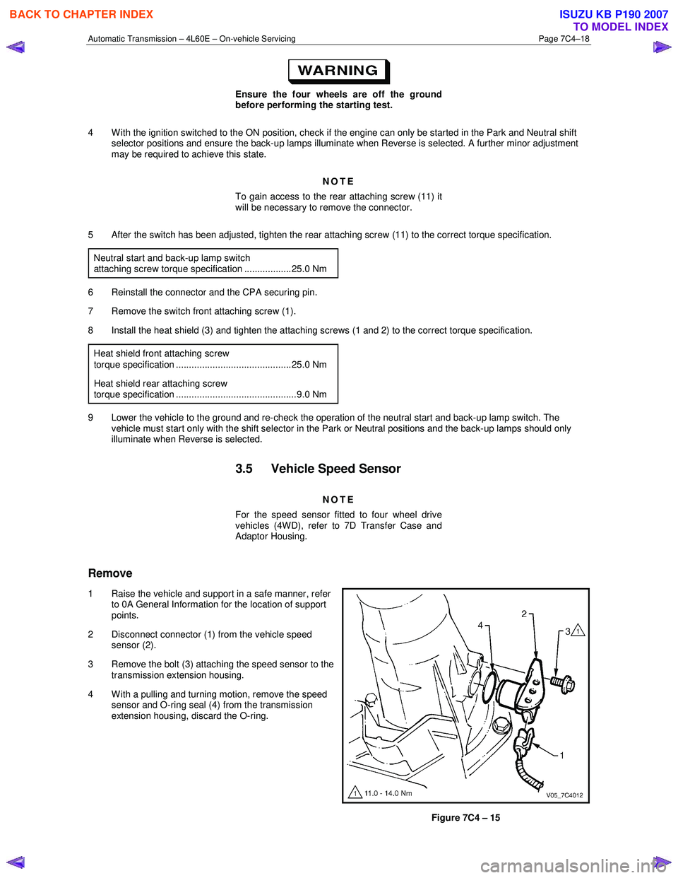
1 Raise the vehicle and support in a safe manner, refer
to 0A General Information for the location of support
points.
2 Disconnect connector (1) from the vehicle speed sensor (2).
3 Remove the bolt (3) attaching the speed sensor to the transmission extension housing.
4 With a pulling and turning motion, remove the speed sensor and O-ring seal (4) from the transmission
extension housing, discard the O-ring.
Figure 7C4 – 15
BACK TO CHAPTER INDEX
TO MODEL INDEX
ISUZU KB P190 2007
Page 3956 of 6020
Automatic Transmission – 4L60E – On-vehicle Servicing Page 7C4–43
If the verifier disc does not clip into place, the
quick-connect fitting is not engaged, rectify
as required.
10 As a security check, push and clip each verification disc into place over the quick-connect fittings. If difficulty is experienced, repeat the installation process until the verification disc can be clipped into place over the radiator
quick-connect fitting.
11 Snap the outlet cooler line (4) in the clip (5) of the radiator fan shroud.
12 Ensure the routeing of the cooler lines is correct and there is no fouling of the lines.
13 Tighten the screw attaching the cooler lines bracket to the correct torque specifications.
Transmission cooler lines bracket
attaching screw torque specification .................. 23.0 Nm
14 If required, top up the transmission fluid level (cold).
15 Start the engine and check for any fluid leak at the fittings. If a leak is found, stop the engine and rectify the leak.
16 Check and top up the transmission fluid to the correct level as required, refer to 2.1 Transmission Fluid.
3.18 Transmission Assembly
Remove
Disconnection of the battery affects certain
vehicle electronic systems. Refer to 6D1-3
Battery, before disconnecting the battery.
1 Disconnect the battery ground lead.
2 Raise the vehicle and support in a safe manner, refer to 0A General Information for the location of support points.
3 Remove the heat shield from the neutral start and back-up lamp switch, gently prise the selector cable from the transmission external manual shaft linkage and remove the selector cable from the bracket, refer to
3.3 Selector Cable Assembly.
4 Disconnect the harness connectors from the following:
a Vehicle speed sensor, refer to 3.5 Vehicle Speed Sensor.
b Neutral start and back-up switch, refer to 3.4 Neutral Start and Back-up Lamp Switch.
c For the following on four wheel drive vehicles (4W D), refer to 7D Transfer Case and Adaptor Housing:
• neutral switch,
• 2WD – 4WD shift actuator switch,
• speed sensor.
NOTE
If the battery is connected, avoid turning the
ignition switch to the ON position, as the transfer
case control module (TTCM) must first be
removed (memory to be cleared as Check 4W D
Indicator will light).
5 Remove the following components: a Front and centre exhaust assemblies, refer to 6F Exhaust System.
BACK TO CHAPTER INDEX
TO MODEL INDEX
ISUZU KB P190 2007
Page 3959 of 6020
Automatic Transmission – 4L60E – On-vehicle Servicing Page 7C4–46
Reinstall
1 If required on 4W D vehicle, reinstall the transfer case, refer to 7D Transfer Case and Adaptor Housing.
2 Ensure the transmission and the engine mating surfaces are clean and free of burrs.
3 Lubricate the torque converter spigot (7) with a small amount of high temperature wheel bearing grease, refer to Figure 7C4 – 62.
4 Install a new filler tube seal into the transmission case.
Support the transmission while installing the
attaching bolts to avoid damage to the torque
converter and flexplate. Do not have the
transmission hanging.
5 Bring the transmission up to the engine, inserting the filler tube and ensuring the locating dowels completely enter the torque converter housing.
6 Reconnect the breather hose to the top of the transmission case.
NOTE
The bolts attaching the torque converter housing
are facing forward except for the bolt in position ℑ
which is facing rearward.
7 With the transmission supported, install the bolt (1), nine places, attaching the torque converter housing to the engine and tighten to the correct torque specification following the sequence shown in
within Figure 7C4 – 62.
Torque converter housing attaching
bolt torque specification .......................... 52.0 – 66.0 Nm
8 Remove the access hole cover plate from the lower surface of the housing and push the torque converter forward to meet the flexplate, then hand start three new bolts (2) before tightening to the correct torque specification.
Reinstall the access hole cover plate.
Torque converter to flexplate attaching
bolt torque specification .......................... 60.0 – 70.0 Nm
9 Reinstall the bolt (3) and torque converter cover (4) on the transmission right-hand side and the bolt (5) and torque converter cover (6) on the transmission left-hand side, tighten the bolts to the correct torque specification.
Torque converter cover attaching
bolt torque specification .......................... 12.0 – 16.0 Nm
10 Reinstall the transmission fluid lines, refer to 3.17 Transmission Cooler Line/Hose Assemblies.
Prior to connecting the harness connector to
the transmission, check that all pins and
seals are in sound condition and the dust
boot is not torn or damaged.
11 Reconnect the transmission harness connector to the transmission as follows: a Push straight down on the connector body until a click is heard.
b Reinstall the dust boot ensuring it is correctly located.
12 Attach the harness clips to the right-hand and left-hand sides of the transmission case, refer to 12O Fuses, Relays and Wiring Harnesses.
13 On 4WD vehicle, connect the harness two clips from the upper side of the transfer case.
BACK TO CHAPTER INDEX
TO MODEL INDEX
ISUZU KB P190 2007
Page 3960 of 6020
Automatic Transmission – 4L60E – On-vehicle Servicing Page 7C4–47
14 Reconnect the fuel and EVAP pipes three brackets and clips, refer to 6C Fuel System – V6.
15 Reinstall the following components:
a Starter motor, refer to 6D1-2 Starting System.
b Transmission support, refer to 3.7 Transmission Support and Mount.
c Front and centre exhaust assemblies, refer to 6F Exhaust System.
d Rear propeller shaft and for 4WD front propeller shaft, refer to 4A Propeller Shaft.
16 Reconnect the harness connectors to the following: a Vehicle speed sensor, refer to 3.5 Vehicle Speed Sensor.
b Neutral start and back-up switch, refer to 3.4 Neutral Start and Back-up Lamp Switch.
c For the following on 4W D vehicles, refer to 7D Transfer Case and Adaptor Housing:
• neutral switch,
• 2WD – 4WD shift actuator switch,
• speed sensor.
17 Reinstall the selector cable to the transmission external manual shaft linkage, secure the selector cable to the bracket and attach the heat shield to the neutral start and back-up lamp switch, refer to 3.3 Selector Cable
Assembly.
18 Perform a reverse flush of the cooler lines and a flow rate test, refer to 2.2 Reverse Flush and Flow Rate, if either of the following applies:
• the transmission fluid is contaminated,
• the transmission has been replaced,
• the torque converter has been replaced, or
• the transmission oil pump has been replaced.
19 Lower the vehicle to the ground.
20 If required, top up the transmission fluid level (cold).
21 Reconnect the battery ground lead.
22 Start the engine and check for any fluid leaking at the fittings. If a leak is found, stop the engine and rectify the leak.
23 Road test until the transmission has reached operating temperature. Re-check the fluid level and for any fluid leaks, refer to 2.1 Transmission Fluid.
3.19 Transmission Control Module
Remove
1 Ensure the ignition switch is in the OFF position.
2 Disconnect the connector (1) from the transmission control module (TCM) (2) as follows, refer to Figure 7C4 – 63: a remove the securing pin (3),
b press the locking tab and swing the lever (4) to free the connector,
c remove the connector.
3 Remove the four bolts (5) and nuts (6), then the TCM from the mounting bracket (7).
4 If required, remove the two nuts (8) and the mounting bracket from the firewall.
BACK TO CHAPTER INDEX
TO MODEL INDEX
ISUZU KB P190 2007
Page 4242 of 6020
CONSTRUCTION AND FUNCTION 7A1-3
DESCRIPTION
CONSTRUCTION
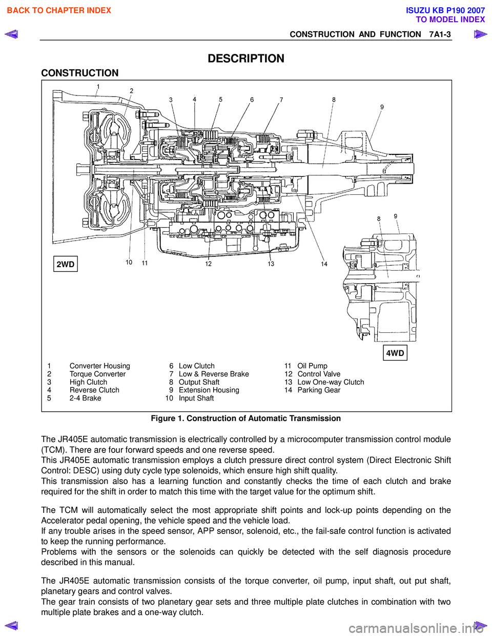
1 Converter Housing 6 Low Clutch 11 Oil Pump
2 Torque Converter 7 Low & Reverse Brake 12 Control Valve
3 High Clutch 8 Output Shaft 13 Low One-way Clutch
4 Reverse Clutch 9 Extension Housing 14 Parking Gear
5 2-4 Brake 10 Input Shaft
Figure 1. Construction of Automatic Transmission
The JR405E automatic transmission is electrically controlled by a microcomputer transmission control module
(TCM). There are four forward speeds and one reverse speed.
This JR405E automatic transmission employs a clutch pressure direct control system (Direct Electronic Shift
Control: DESC) using duty cycle type solenoids, which ensure high shift quality.
This transmission also has a learning function and constantly checks the time of each clutch and brake
required for the shift in order to match this time with the target value for the optimum shift.
The TCM will automatically select the most appropriate shift points and lock-up points depending on the
Accelerator pedal opening, the vehicle speed and the vehicle load.
If any trouble arises in the speed sensor, APP sensor, solenoid, etc., the fail-safe control function is activated
to keep the running performance.
Problems with the sensors or the solenoids can quickly be detected with the self diagnosis procedure
described in this manual.
The JR405E automatic transmission consists of the torque converter, oil pump, input shaft, out put shaft,
planetary gears and control valves.
The gear train consists of two planetary gear sets and three multiple plate clutches in combination with two
multiple plate brakes and a one-way clutch.
2WD
4WD
BACK TO CHAPTER INDEX
TO MODEL INDEX
ISUZU KB P190 2007
Page 4245 of 6020
7A1-6 CONSTRUCTION AND FUNCTION
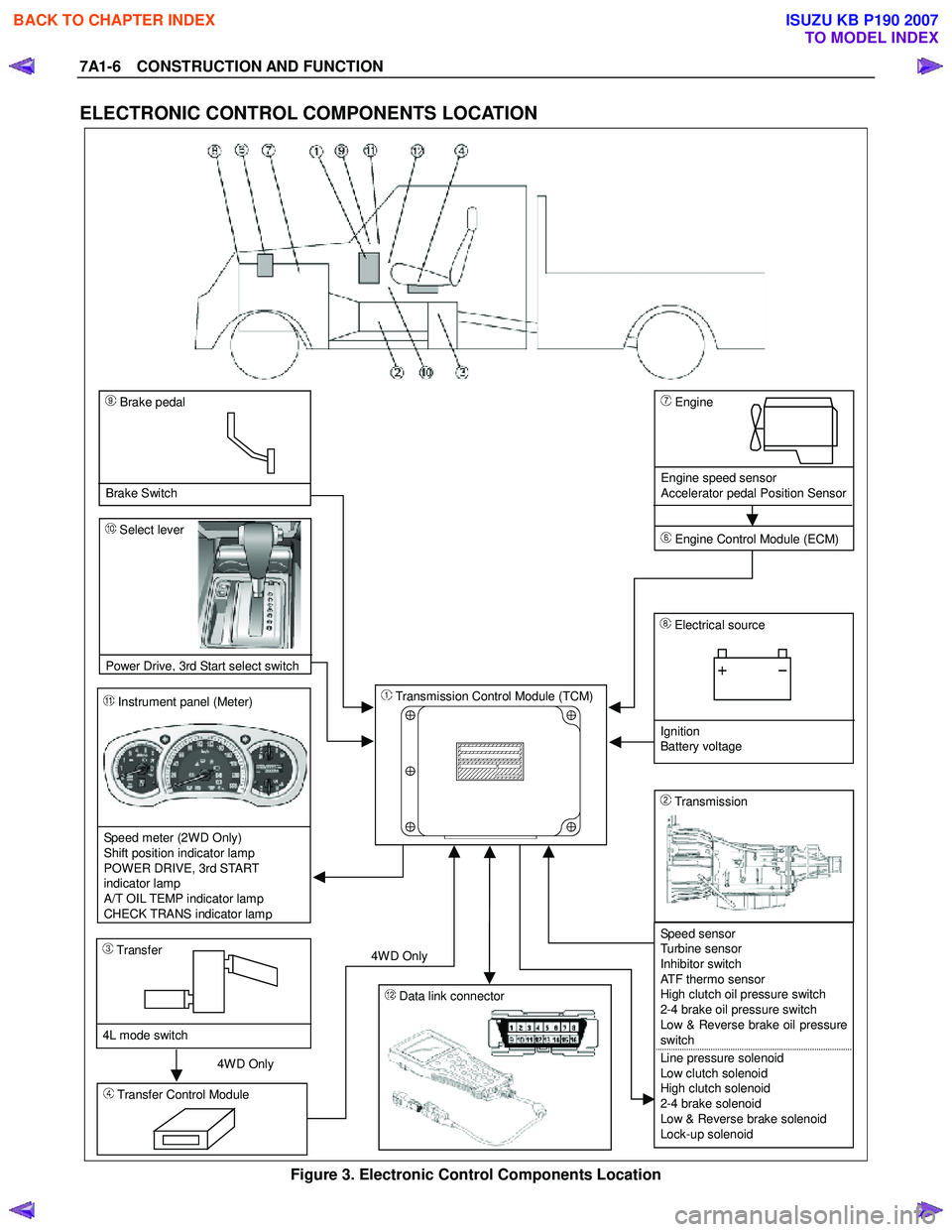
ELECTRONIC CONTROL COMPONENTS LOCATION
4WD Only 4W D Only
Instrument panel (Meter)
Speed meter (2WD Only)
Shift position indicator lamp
POWER DRIVE, 3rd START
indicator lamp
A/T OIL TEMP indicator lamp
CHECK TRANS indicator lam
p
Brake pedal
Brake Switch
Transmission Control Module (TCM)
Electrical source
Ignition
Battery voltage
Speed sensor
Turbine sensor
Inhibitor switch
ATF thermo sensor
High clutch oil pressure switch
2-4 brake oil pressure switch
Low & Reverse brake oil pressure
switch
Line pressure solenoid
Low clutch solenoid
High clutch solenoid
2-4 brake solenoid
Low & Reverse brake solenoid
Lock-up solenoid
Transmission
Transfer Control Module
Transfer
4L mode switch
Engine
Engine speed sensor
Accelerator pedal Position Sensor
Engine Control Module (ECM)
Data link connector
Select lever
Power Drive
, 3rd Start select switch
Figure 3. Electronic Control Components Location
BACK TO CHAPTER INDEX
TO MODEL INDEX
ISUZU KB P190 2007
Page 4301 of 6020
TRANSMISSION CONTROL SYSTEM (JR405E) 7A2-17
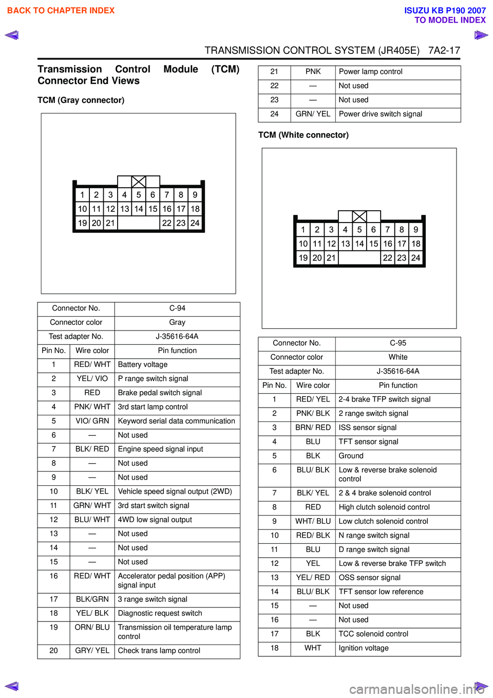
Transmission Control Module (TCM)
Connector End Views
TCM (Gray connector)
TCM (White connector)
Connector No.C-94
Connector color Gray
Test adapter No. J-35616-64A
Pin No. Wire color Pin function
1 RED/ WHT Battery voltage
2 YEL/ VIO P range switch signal
3 RED Brake pedal switch signal
4 PNK/ WHT 3rd start lamp control
5 VIO/ GRN Keyword serial data communication
6 — Not used
7 BLK/ RED Engine speed signal input
8 — Not used
9 — Not used
10 BLK/ YEL Vehicle speed signal output (2WD)
11 GRN/ WHT 3rd start switch signal
12 BLU/ WHT 4WD low signal output
13 — Not used
14 — Not used
15 — Not used
16 RED/ WHT Accelerator pedal position (APP) signal input
17 BLK/GRN 3 range switch signal
18 YEL/ BLK Diagnostic request switch
19 ORN/ BLU Transmission oil temperature lamp control
20 GRY/ YEL Check trans lamp control
1
10
19
2
11
20
3
12
21
4
13
5
14
6
15
7
16
22
8
17
23
9
18
24
21 PNK Power lamp control
22 — Not used
23 — Not used
24 GRN/ YEL Power drive switch signal
Connector No. C-95
Connector color White
Test adapter No. J-35616-64A
Pin No. Wire color Pin function
1 RED/ YEL 2-4 brake TFP switch signal
2 PNK/ BLK 2 range switch signal
3 BRN/ RED ISS sensor signal
4 BLU TFT sensor signal
5 BLK Ground
6 BLU/ BLK Low & reverse brake solenoid control
7 BLK/ YEL 2 & 4 brake solenoid control
8 RED High clutch solenoid control
9 WHT/ BLU Low clutch solenoid control
10 RED/ BLK N range switch signal 11 BLU D range switch signal
12 YEL Low & reverse brake TFP switch
13 YEL/ RED OSS sensor signal
14 BLU/ BLK TFT sensor low reference
15 — Not used
16 — Not used
17 BLK TCC solenoid control
18 WHT Ignition voltage
1
10
19
2
11
20
3
12
21
4
13
5
14
6
15
7
16
22
8
17
23
9
18
24
BACK TO CHAPTER INDEX
TO MODEL INDEX
ISUZU KB P190 2007