2007 ISUZU KB P190 Neutral switch
[x] Cancel search: Neutral switchPage 303 of 6020

3B-42 POWER-ASSISTED STEERING SYSTEM
CAUTION: When turning the SRS coil fully
counterclockwise, stop turning if resistance is felt.
Further forced turning may damage the cable in the
SRS coil (with SRS air bag).
826RW 014
Legend
(1) Neutral mark
RTW 73BSH001301
16. Remove steering column cover.
17. Disconnect the wiring harness connectors located under the steering column then remove combination
switch and SRS coil assembly (with SRS air bag).
NOTE: The SRS coil is a part of the combination switch
assembly, which cannot be replaced separately.
Therefore, be sure not to remove the SRS coil from the
combination switch assembly (with SRS air bag).
RTW 73BSH001001
Installation
1. Install the combination switch assembly with SRS coil (with SRS air bag).
2. Turn the SRS coil fully counterclockwise, return about 3 turns and align the neutral mark (with SRS
air bag).
3. Connect the wiring harness connectors located at the base of steering column.
4. Install the air conditioning lower duct.
5. Install the steering column cover.
CAUTION: When installing the steering column
cover, be sure to wire (through each harness) as
illustrated so that the harness starter switch,
combination switch and SRS coil will not catch
wiring (with SRS air bag).
825RS048
BACK TO CHAPTER INDEX
TO MODEL INDEX
ISUZU KB P190 2007
Page 309 of 6020

3B-48 POWER-ASSISTED STEERING SYSTEM
430R300007
17. Remove steering column cover.
18. Disconnect the wiring harness connectors located under the steering column.
19. Remove the combination switch assembly with SRS coil.
NOTE: The SRS coil is a part of the combination switch
assembly, which cannot be replaced separately.
Therefore, be sure not to remove the SRS coil from the
combination switch assembly (with SRS air bag).
RTW 73BSH001001
20. Turn the ignition switch to the ACC position.
21. Insert a pin (1) into the hole and push on it. Pull the
key cylinder free.
RUW 53BSH000101
Installation
1. Install lock cylinder assembly.
2. Install the combination switch assembly with SRS coil (with SRS air bag).
3. Turn the SRS coil fully counterclockwise, return about 3 turns and align the neutral mark (with SRS
air bag).
CAUTION: When turning the SRS coil fully
counterclockwise, stop turning if resistance is felt.
Further forced turning may damage the cable in the
SRS coil (with SRS air bag).
826RW 014
Legend
(1) Neutral mark
BACK TO CHAPTER INDEX
TO MODEL INDEX
ISUZU KB P190 2007
Page 317 of 6020

3B-56 POWER-ASSISTED STEERING SYSTEM
9. Turn the SRS coil fully counterclockwise, return
about 3 turns and align the neutral mark (1). (with
SRS air bag)
CAUTION: When turning the SRS coil fully
counterclockwise, stop turning if resistance is felt.
Further forced turning may damage to the cable in
the SRS coil.
826RW 014
10. W hen installing the steering column cover, be sure to
route each wiring harness as illustrated so that the
harnesses do not catch any moving parts.
825RW 017
Legend
(1) Steering Column Cover
(2) Starter Switch Harness
(3) Combination Switch Harness
(4) Inflator Module Harness
11. Install steering wheel and align the setting marks
made when removing. Refer to the adjustment method in case a mark has
not been applied in this section.
NOTE: Confirm SRS and horn harness connector is
fixed by the steering wheel.
RTW 73BSH000701
CAUTION: Never apply force to the steering wheel in
the direction of the shaft by using a hammer o
r
other impact tools in an attempt to remove the
steering wheel. The steering shaft is designed as an
energy absorbing unit.
12. Tighten the steering wheel fixing nut to the specified torque.
Torque: 35 N ⋅
⋅⋅
⋅
m (3.6 kgf ⋅
⋅⋅
⋅
m/26 lb ⋅
⋅⋅
⋅
ft)
13. Support the module and carefully connect the module connector and horn lead, then install inflato
r
module.
NOTE: Pass the lead wire through the tabs on the
plastic cover (wire protector) of inflator to prevent lead
wire from being pinched.
14. Tighten bolts to specified torque.
Torque: 3 N ⋅
⋅⋅
⋅
m (0.3 kgf ⋅
⋅⋅
⋅
m/26 lb ⋅
⋅⋅
⋅
in)
15. Install driver knee bolster (reinforcement).
16. Install instrument panel lower cover.
17. Install the engine hood opening lever.
18. Connect the yellow 2-way SRS connector and horn lead located under the steering column.
19. Connect the battery "-" terminal cable (with SRS ai
r
bag).
BACK TO CHAPTER INDEX
TO MODEL INDEX
ISUZU KB P190 2007
Page 1048 of 6020
6E-14 Engine Control System (4JH1)
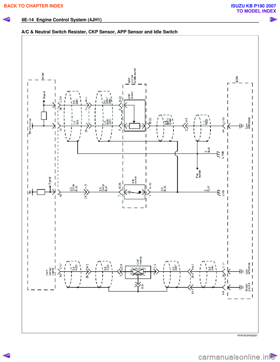
A/C & Neutral Switch Resister, CKP Sensor, APP Sensor and Idle Switch
RTW 76EXF003201
BACK TO CHAPTER INDEX
TO MODEL INDEX
ISUZU KB P190 2007
Page 1050 of 6020
6E-16 Engine Control System (4JH1)
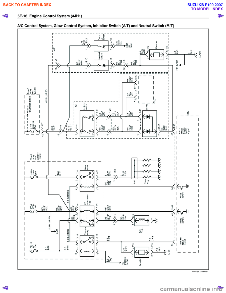
A/C Control System, Glow Control System, Inhibitor Switch (A/T) and Neutral Switch (M/T)
RTW 76EXF003401
BACK TO CHAPTER INDEX
TO MODEL INDEX
ISUZU KB P190 2007
Page 1058 of 6020
6E-24 Engine Control System (4JH1)
RTW 66ESF000401
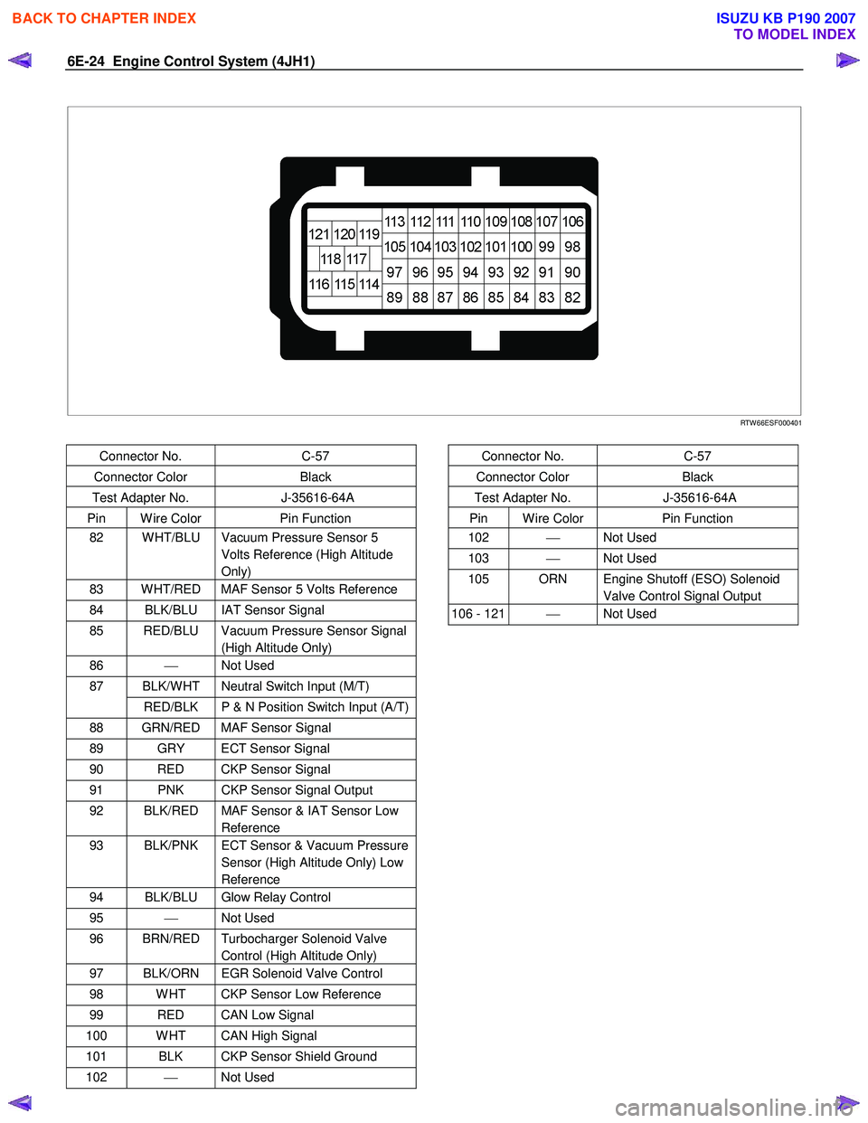
Connector No. C-57
Connector Color Black
Test Adapter No. J-35616-64A
Pin W ire Color Pin Function
82 W HT/BLU Vacuum Pressure Sensor 5
Volts Reference (High Altitude
Only)
83 W HT/RED MAF Sensor 5 Volts Reference
84 BLK/BLU IAT Sensor Signal
85 RED/BLU Vacuum Pressure Sensor Signal (High Altitude Only)
86 Not Used
BLK/W HT Neutral Switch Input (M/T) 87
RED/BLK P & N Position Switch Input (A/T)
88 GRN/RED MAF Sensor Signal
89 GRY ECT Sensor Signal
90 RED CKP Sensor Signal
91 PNK CKP Sensor Signal Output
92 BLK/RED MAF Sensor & IAT Sensor Low Reference
93 BLK/PNK ECT Sensor & Vacuum Pressure Sensor (High Altitude Only) Low
Reference
94 BLK/BLU Glow Relay Control
95 Not Used
96 BRN/RED Turbocharger Solenoid Valve
Control (High Altitude Only)
97 BLK/ORN EGR Solenoid Valve Control
98 W HT CKP Sensor Low Reference
99 RED CAN Low Signal
100 W HT CAN High Signal
101 BLK CKP Sensor Shield Ground
102 Not Used
Connector No. C-57
Connector Color Black
Test Adapter No. J-35616-64A
Pin W ire Color Pin Function
102 Not Used
103 Not Used
105 ORN Engine Shutoff (ESO) Solenoid
Valve Control Signal Output
106 - 121 Not Used
BACK TO CHAPTER INDEX
TO MODEL INDEX
ISUZU KB P190 2007
Page 1070 of 6020
6E-36 Engine Control System (4JH1)
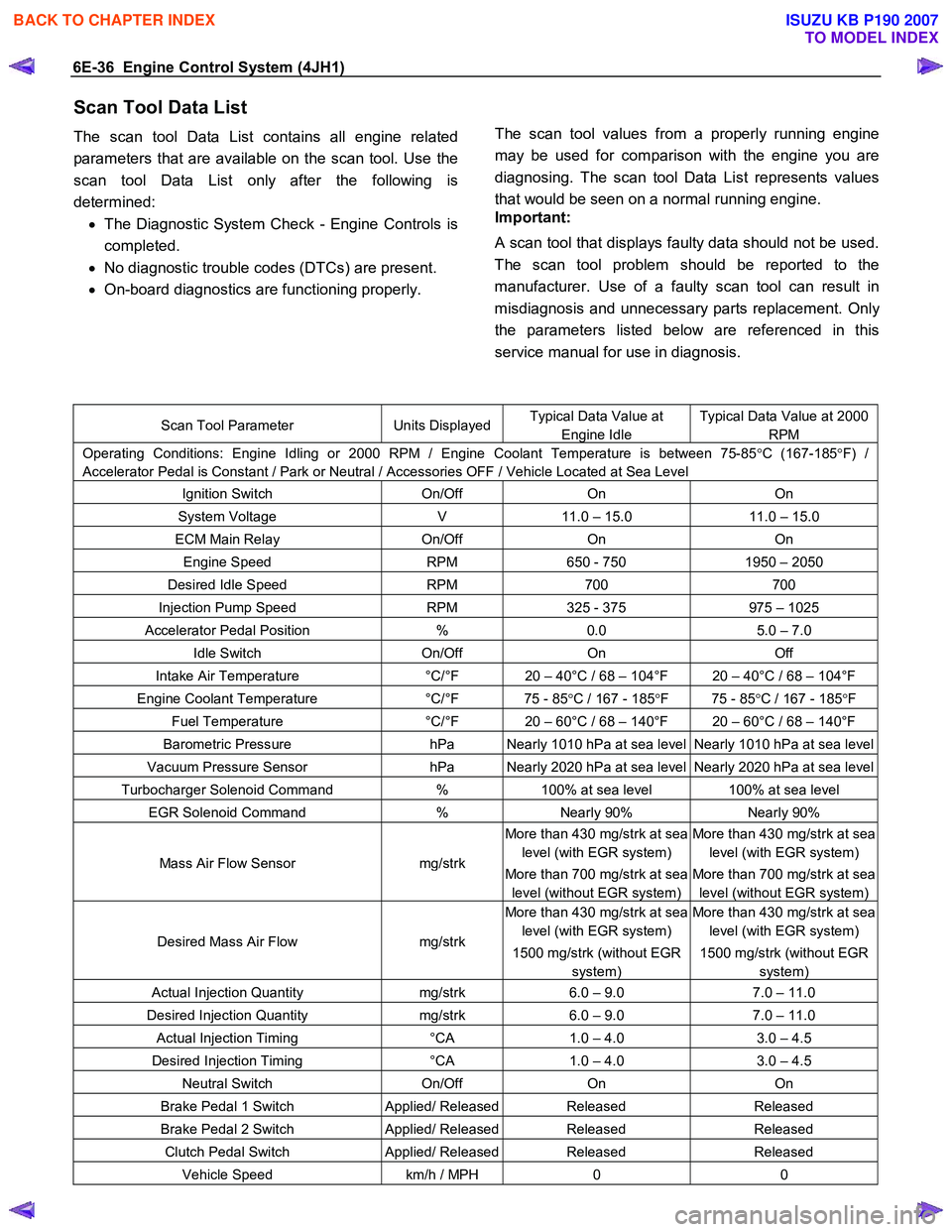
Scan Tool Data List
The scan tool Data List contains all engine related
parameters that are available on the scan tool. Use the
scan tool Data List only after the following is
determined: • The Diagnostic System Check - Engine Controls is
completed.
• No diagnostic trouble codes (DTCs) are present.
• On-board diagnostics are functioning properly.
The scan tool values from a properly running engine
may be used for comparison with the engine you are
diagnosing. The scan tool Data List represents values
that would be seen on a normal running engine.
Important:
A scan tool that displays faulty data should not be used.
The scan tool problem should be reported to the
manufacturer. Use of a faulty scan tool can result in
misdiagnosis and unnecessary parts replacement. Onl
y
the parameters listed below are referenced in this
service manual for use in diagnosis.
Scan Tool Parameter Units DisplayedTypical Data Value at
Engine Idle
Typical Data Value at 2000
RPM
Operating Conditions: Engine Idling or 2000 RPM / Engine Coolant Temperature is between 75-85 °C (167-185 °F) /
Accelerator Pedal is Constant / Park or Neutral / Accessories OFF / Vehicle Located at Sea Level
Ignition Switch On/Off On On
System Voltage V 11.0 – 15.0 11.0 – 15.0
ECM Main Relay On/Off On On
Engine Speed RPM 650 - 750 1950 – 2050
Desired Idle Speed RPM 700 700
Injection Pump Speed RPM 325 - 375 975 – 1025
Accelerator Pedal Position % 0.0 5.0 – 7.0
Idle Switch On/Off On Off
Intake Air Temperature °C/°F 20 – 40°C / 68 – 104°F 20 – 40°C / 68 – 104°F
Engine Coolant Temperature °C/°F 75 - 85 °C / 167 - 185 °F 75 - 85 °C / 167 - 185 °F
Fuel Temperature °C/°F 20 – 60°C / 68 – 140°F 20 – 60°C / 68 – 140°F
Barometric Pressure hPa Nearly 1010 hPa at sea level Nearly 1010 hPa at sea level
Vacuum Pressure Sensor hPa Nearly 2020 hPa at sea level Nearly 2020 hPa at sea level
Turbocharger Solenoid Command % 100% at sea level 100% at sea level
EGR Solenoid Command % Nearly 90% Nearly 90%
Mass Air Flow Sensor mg/strk
More than 430 mg/strk at sea
level (with EGR system)
More than 700 mg/strk at sea
level (without EGR system)
More than 430 mg/strk at sea
level (with EGR system)
More than 700 mg/strk at sea
level (without EGR system)
Desired Mass Air Flow mg/strk
More than 430 mg/strk at sea
level (with EGR system)
1500 mg/strk (without EGR
system)
More than 430 mg/strk at sea
level (with EGR system)
1500 mg/strk (without EGR
system)
Actual Injection Quantity mg/strk 6.0 – 9.0 7.0 – 11.0
Desired Injection Quantity mg/strk 6.0 – 9.0 7.0 – 11.0
Actual Injection Timing °CA 1.0 – 4.0 3.0 – 4.5
Desired Injection Timing °CA 1.0 – 4.0 3.0 – 4.5
Neutral Switch On/Off On On
Brake Pedal 1 Switch Applied/ ReleasedReleased Released
Brake Pedal 2 Switch Applied/ ReleasedReleased Released
Clutch Pedal Switch Applied/ ReleasedReleased Released
Vehicle Speed km/h / MPH 0 0
BACK TO CHAPTER INDEX
TO MODEL INDEX
ISUZU KB P190 2007
Page 1072 of 6020
6E-38 Engine Control System (4JH1)
Intake Air Temperature
This parameter displays the temperature of the intake
air based on a voltage input from the intake ai
r
temperature (IAT) sensor to the ECM. The scan tool will
display a low temperature when signal voltage is high,
and high temperature when the signal voltage is low.
Note that the IAT sensor is internal to the mass air flo
w
(MAF) sensor and the MAF sensor is heated.
Engine Coolant Temperature
This parameter displays the temperature of the engine
coolant based on a voltage input from the engine
coolant temperature (ECT) sensor to the ECM. The
scan tool will display a low temperature when the signal
voltage is high, and a high temperature when the signal
voltage is low.
Fuel Temperature
This parameter displays the temperature of the fuel as
calculated by the fuel injection pump control unit (PCU)
using the signal from the fuel temperature sensor inside
of the PCU.
Barometric Pressure
This parameter displays the barometric pressure as
calculated by the ECM using the signal from the
barometric pressure (BARO) sensor inside of the ECM.
Vacuum Pressure Sensor (High altitude
specification only)
This parameter displays the amount of the vacuum
pressure to the turbocharger wastegate valve. W hen a
high vacuum pressure at a low vacuum pressure
amount to the turbocharger wastegate valve. The scan
tool will display doubled barometric pressure when the
ignition is ON with the engine OFF.
Turbocharger Solenoid Command (High altitude
specification only)
This parameter displays the turbocharger solenoid
valuve control duty ratio commanded by the ECM
terminal (pin 96) using the signal from various senso
r
inputs. W hen a low duty ratio, vacuum pressure to the
turbocharger wastegate valve is controlled to increase.
W hen a high duty ratio, vacuum pressure to the
turbochager wastegate valve is controlled to reduce.
EGR Solenoid Command
This parameter displays the EGR solenoid valve control
duty ratio commanded by the ECM terminal (pin 97)
using the signal from engine speed, and injection
volume and various sensor inputs. W hen a small dut
y
ratio, the EGR valve is controlled to close. W hen a large
duty ratio, the EGR valve is controlled to open.
Mass Air Flow Sensor
This parameter displays the air flow into the engine as
calculated by the ECM based on the mass air flo
w
(MAF) sensor input. The scan tool will display a high
value at higher engine speeds, and a low value at idle.
This can be compared to the Desired Mass Air Flow to
determine MAF sensor accuracy, EGR problem o
r
intake problem. Note that the MAF on the scan tool will
only update with the engine running.
Desired Mass Air Flow
This parameter displays a mass air flow desired by the
ECM based on current driving condition.
Actual Injection Quantity
This parameter displays the injection quantity calculated
by the PCU based on the fuel injection solenoid valve
On time which compensated from the timing device
position and fuel temperature inputs. This can be
compared to the Desired Injection Quantity to determine
fuel system problem.
Desired Injection Quantity
This parameter displays an injection quantity desired b
y
the ECM based on current driving condition using target
injection maps.
Actual Injection Timing
This parameter displays the injection timing calculated
by the PCU based on the timing device position which
determined from the crankshaft position sensor and
camshaft position sensor inputs. This can be compared
to the Desired Injection Timing to determine timing
device problem or fuel system problem.
Desired Injection Timing
This parameter displays injection timing desired by the
ECM based on current driving condition using target
injection timing maps. This timing is compensated b
y
engine coolant temperature, altitude and intake ai
r
temperature, etc.
Neutral Switch
This parameter displays the state of the neutral switch
as determined by the ECM terminal (pin 87) based on
an input from the neutral switch or inhibitor switch.
Brake Pedal 1 Switch
This parameter displays the state of the brake pedal as
determined by the ECM terminal (pin 30) based on an
input from the brake pedal 1 switch. This switch turns
On the stop lamps when the brake pedal is depressed.
The scan tool will display Applied when the brake pedal
is depressed.
BACK TO CHAPTER INDEX
TO MODEL INDEX
ISUZU KB P190 2007