2007 ISUZU KB P190 Neutral switch
[x] Cancel search: Neutral switchPage 1971 of 6020
6E-354 ENGINE CONTROL SYSTEM (4JK1/4JJ1)
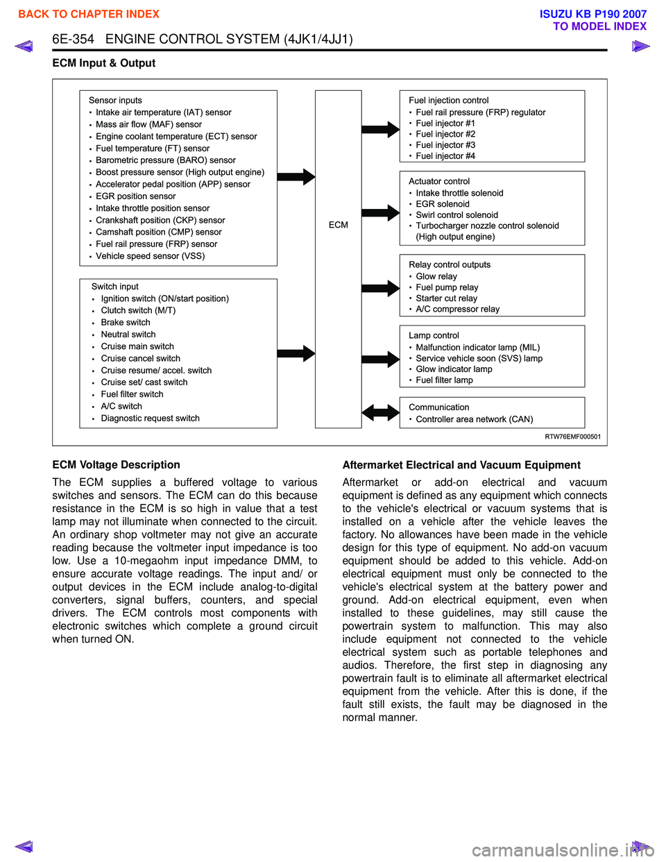
ECM Input & Output
ECM Voltage Description
The ECM supplies a buffered voltage to various
switches and sensors. The ECM can do this because
resistance in the ECM is so high in value that a test
lamp may not illuminate when connected to the circuit.
An ordinary shop voltmeter may not give an accurate
reading because the voltmeter input impedance is too
low. Use a 10-megaohm input impedance DMM, to
ensure accurate voltage readings. The input and/ or
output devices in the ECM include analog-to-digital
converters, signal buffers, counters, and special
drivers. The ECM controls most components with
electronic switches which complete a ground circuit
when turned ON. Aftermarket Electrical and Vacuum Equipment
Aftermarket or add-on electrical and vacuum
equipment is defined as any equipment which connects
to the vehicle's electrical or vacuum systems that is
installed on a vehicle after the vehicle leaves the
factory. No allowances have been made in the vehicle
design for this type of equipment. No add-on vacuum
equipment should be added to this vehicle. Add-on
electrical equipment must only be connected to the
vehicle's electrical system at the battery power and
ground. Add-on electrical equipment, even when
installed to these guidelines, may still cause the
powertrain system to malfunction. This may also
include equipment not connected to the vehicle
electrical system such as portable telephones and
audios. Therefore, the first step in diagnosing any
powertrain fault is to eliminate all aftermarket electrical
equipment from the vehicle. After this is done, if the
fault still exists, the fault may be diagnosed in the
normal manner.
RTW76EMF000501
Sensor inputs
· Intake air temperature (IAT) sensor
· Mass air flow (MAF) sensor
· Engine coolant temperature (ECT) sensor
· Fuel temperature (FT) sensor
· Barometric pressure (BARO) sensor
· Boost pressure sensor (High output engine)
· Accelerator pedal position (APP) sensor
· EGR position sensor
· Intake throttle position sensor
· Crankshaft position (CKP) sensor
· Camshaft position (CMP) sensor
· Fuel rail pressure (FRP) sensor
· Vehicle speed sensor (VSS)
Switch input
· Ignition switch (ON/start position)
· Clutch switch (M/T)
· Brake switch
· Neutral switch
· Cruise main switch
· Cruise cancel switch
· Cruise resume/ accel. switch
· Cruise set/ cast switch
· Fuel filter switch
· A/C switch
· Diagnostic request switch
Fuel injection control
· Fuel rail pressure (FRP) regulator
· Fuel injector #1
· Fuel injector #2
· Fuel injector #3
· Fuel injector #4
Relay control outputs
· Glow relay
· Fuel pump relay
· Starter cut relay
· A/C compressor relay
Lamp control
· Malfunction indicator lamp (MIL)
· Service vehicle soon (SVS) lamp
· Glow indicator lamp
· Fuel filter lamp
Communication
· Controller area network (CAN)
Actuator control
· Intake throttle solenoid
· EGR solenoid
· Swirl control solenoid
· Turbocharger nozzle control solenoid
(High output engine)ECM
BACK TO CHAPTER INDEX
TO MODEL INDEX
ISUZU KB P190 2007
Page 3293 of 6020
Engine Management – V6 – Diagnostics Page 6C1-2–15
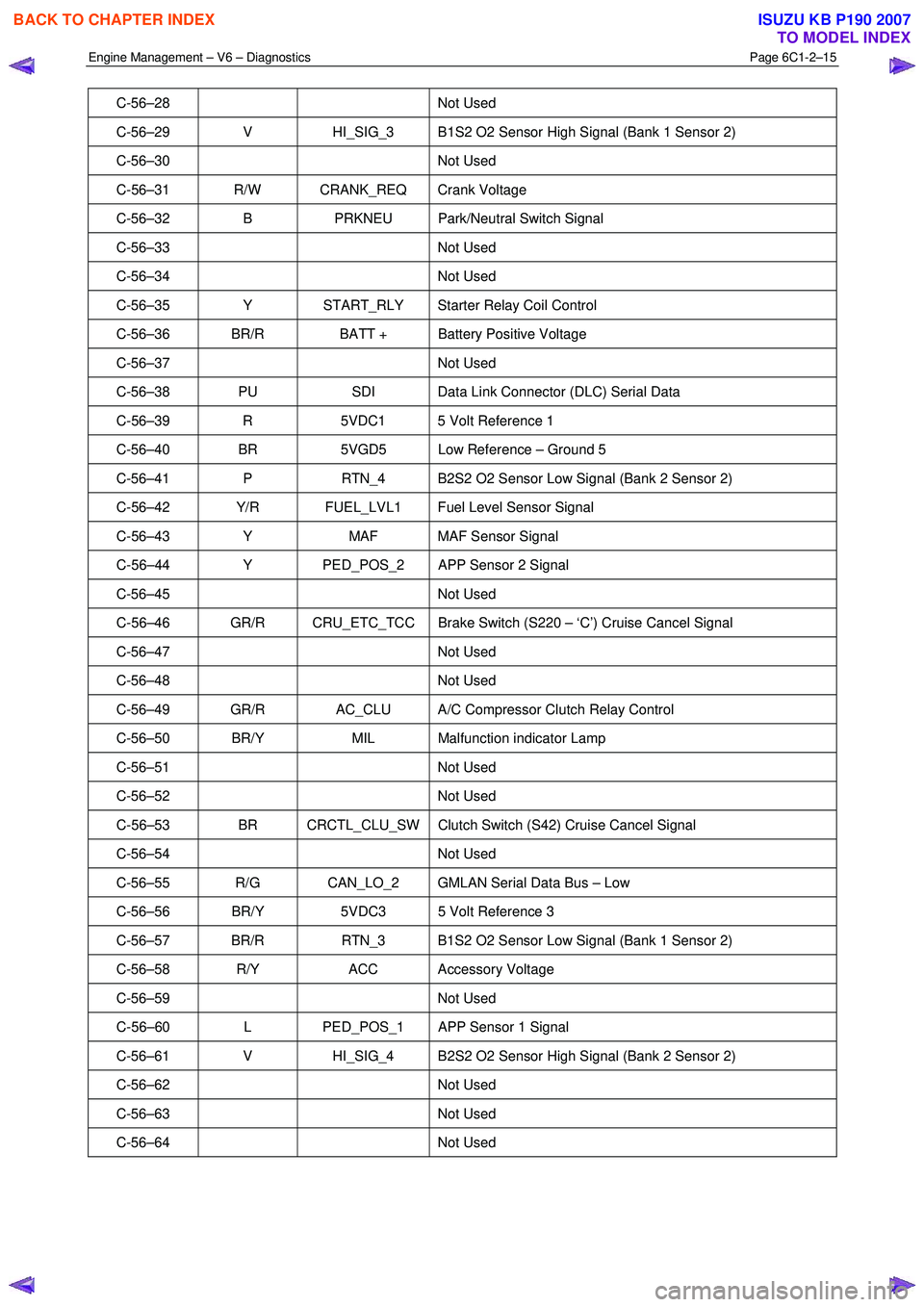
C-56–28 Not Used
C-56–29 V HI_SIG_3 B1S2 O2 Sensor High Signal (Bank 1 Sensor 2)
C-56–30 Not Used
C-56–31 R/W CRANK_REQ Crank Voltage
C-56–32 B PRKNEU Park/Neutral Switch Signal
C-56–33 Not Used
C-56–34 Not Used
C-56–35 Y START_RLY Starter Relay Coil Control
C-56–36 BR/R BATT + Battery Positive Voltage
C-56–37 Not Used
C-56–38 PU SDI Data Link Connector (DLC) Serial Data
C-56–39 R 5VDC1 5 Volt Reference 1
C-56–40 BR 5VGD5 Low Reference – Ground 5
C-56–41 P RTN_4 B2S2 O2 Sensor Low Signal (Bank 2 Sensor 2)
C-56–42 Y/R FUEL_LVL1 Fuel Level Sensor Signal
C-56–43 Y MAF MAF Sensor Signal
C-56–44 Y PED_POS_2 APP Sensor 2 Signal
C-56–45 Not Used
C-56–46 GR/R CRU_ETC_TCC Brake Switch (S220 – ‘C’) Cruise Cancel Signal
C-56–47 Not Used
C-56–48 Not Used
C-56–49 GR/R AC_CLU A/C Compressor Clutch Relay Control
C-56–50 BR/Y MIL Malfunction indicator Lamp
C-56–51 Not Used
C-56–52 Not Used
C-56–53 BR CRCTL_CLU_SW Clutch Switch (S42) Cruise Cancel Signal
C-56–54 Not Used
C-56–55 R/G CAN_LO_2 GMLAN Serial Data Bus – Low
C-56–56 BR/Y 5VDC3 5 Volt Reference 3
C-56–57 BR/R RTN_3 B1S2 O2 Sensor Low Signal (Bank 1 Sensor 2)
C-56–58 R/Y ACC Accessory Voltage
C-56–59 Not Used
C-56–60 L PED_POS_1 APP Sensor 1 Signal
C-56–61 V HI_SIG_4 B2S2 O2 Sensor High Signal (Bank 2 Sensor 2)
C-56–62 Not Used
C-56–63 Not Used
C-56–64 Not Used
BACK TO CHAPTER INDEX
TO MODEL INDEX
ISUZU KB P190 2007
Page 3334 of 6020
Engine Management – V6 – Diagnostics Page 6C1-2–56
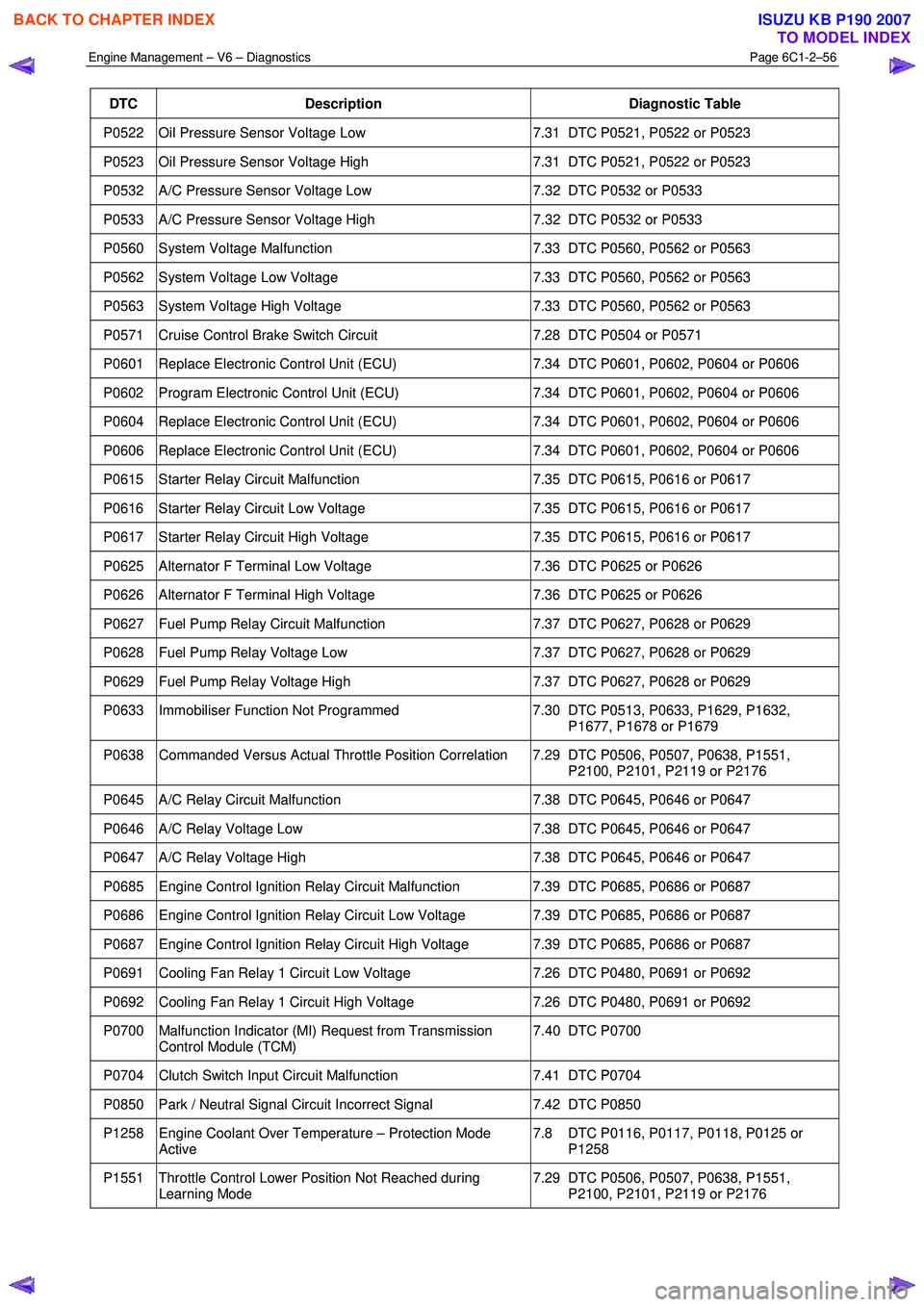
DTC Description Diagnostic Table
P0522 Oil Pressure Sensor Voltage Low 7.31 DTC P0521, P0522 or P0523
P0523 Oil Pressure Sensor Voltage High 7.31 DTC P0521, P0522 or P0523
P0532 A/C Pressure Sensor Voltage Low 7.32 DTC P0532 or P0533
P0533 A/C Pressure Sensor Voltage High 7.32 DTC P0532 or P0533
P0560 System Voltage Malfunction 7.33 DTC P0560, P0562 or P0563
P0562 System Voltage Low Voltage 7.33 DTC P0560, P0562 or P0563
P0563 System Voltage High Voltage 7.33 DTC P0560, P0562 or P0563
P0571 Cruise Control Brake Switch Circuit 7.28 DTC P0504 or P0571
P0601 Replace Electronic Control Unit (ECU) 7.34 DTC P0601, P0602, P0604 or P0606
P0602 Program Electronic Control Unit (ECU) 7.34 DTC P0601, P0602, P0604 or P0606
P0604 Replace Electronic Control Unit (ECU) 7.34 DTC P0601, P0602, P0604 or P0606
P0606 Replace Electronic Control Unit (ECU) 7.34 DTC P0601, P0602, P0604 or P0606
P0615 Starter Relay Circuit Malfunction 7.35 DTC P0615, P0616 or P0617
P0616 Starter Relay Circuit Low Voltage 7.35 DTC P0615, P0616 or P0617
P0617 Starter Relay Circuit High Voltage 7.35 DTC P0615, P0616 or P0617
P0625 Alternator F Terminal Low Voltage 7.36 DTC P0625 or P0626
P0626 Alternator F Terminal High Voltage 7.36 DTC P0625 or P0626
P0627 Fuel Pump Relay Circuit Malfunction 7.37 DTC P0627, P0628 or P0629
P0628 Fuel Pump Relay Voltage Low 7.37 DTC P0627, P0628 or P0629
P0629 Fuel Pump Relay Voltage High 7.37 DTC P0627, P0628 or P0629
P0633 Immobiliser Function Not Programmed 7.30 DTC P0513, P0633, P1629, P1632,
P1677, P1678 or P1679
P0638 Commanded Versus Actual Throttle Position Correlation 7.29 DTC P0506, P0507, P0638, P1551, P2100, P2101, P2119 or P2176
P0645 A/C Relay Circuit Malfunction 7.38 DTC P0645, P0646 or P0647
P0646 A/C Relay Voltage Low 7.38 DTC P0645, P0646 or P0647
P0647 A/C Relay Voltage High 7.38 DTC P0645, P0646 or P0647
P0685 Engine Control Ignition Relay Circuit Malfunction 7.39 DTC P0685, P0686 or P0687
P0686 Engine Control Ignition Relay Circuit Low Voltage 7.39 DTC P0685, P0686 or P0687
P0687 Engine Control Ignition Relay Circuit High Voltage 7.39 DTC P0685, P0686 or P0687
P0691 Cooling Fan Relay 1 Circuit Low Voltage 7.26 DTC P0480, P0691 or P0692
P0692 Cooling Fan Relay 1 Circuit High Voltage 7.26 DTC P0480, P0691 or P0692
P0700 Malfunction Indicator (MI) Request from Transmission
Control Module (TCM) 7.40 DTC P0700
P0704 Clutch Switch Input Circuit Malfunction
7.41 DTC P0704
P0850 Park / Neutral Signal Circuit Incorrect Signal 7.42 DTC P0850
P1258 Engine Coolant Over Temperature – Protection Mode
Active 7.8 DTC P0116, P0117, P0118, P0125 or
P1258
P1551 Throttle Control Lower Position Not Reached during Learning Mode 7.29 DTC P0506, P0507, P0638, P1551,
P2100, P2101, P2119 or P2176
BACK TO CHAPTER INDEX
TO MODEL INDEX
ISUZU KB P190 2007
Page 3410 of 6020
Engine Management – V6 – Diagnostics Page 6C1-2–132
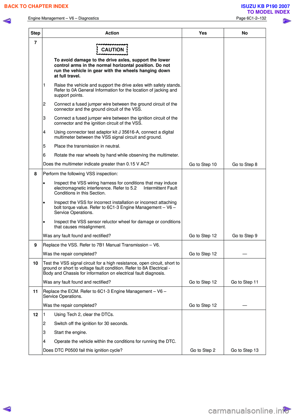
Step Action Yes No
7
To avoid damage to the drive axles, support the lower
control arms in the normal horizontal position. Do not
run the vehicle in gear with the wheels hanging down
at full travel.
1 Raise the vehicle and support the drive axles with safety stands. Refer to 0A General Information for the location of jacking and
support points.
2 Connect a fused jumper wire between the ground circuit of the connector and the ground circuit of the VSS.
3 Connect a fused jumper wire between the ignition circuit of the connector and the ignition circuit of the VSS.
4 Using connector test adaptor kit J 35616-A, connect a digital multimeter between the VSS signal circuit and ground.
5 Place the transmission in neutral.
6 Rotate the rear wheels by hand while observing the multimeter.
Does the multimeter indicate greater than 0.15 V AC? Go to Step 10 Go to Step 8
8 Perform the following VSS inspection:
• Inspect the VSS wiring harness for conditions that may induce
electromagnetic interference. Refer to 5.2 Intermittent Fault
Conditions in this Section.
• Inspect the VSS for incorrect installation or incorrect attaching
bolt torque value. Refer to 6C1-3 Engine Management – V6 –
Service Operations.
• Inspect the VSS sensor reluctor wheel for damage or conditions
that causes misalignment.
W as any fault found and rectified? Go to Step 12 Go to Step 9
9 Replace the VSS. Refer to 7B1 Manual Transmission – V6.
W as the repair completed? Go to Step 12 —
10 Test the VSS signal circuit for a high resistance, open circuit, short to
ground or short to voltage fault condition. Refer to 8A Electrical -
Body and Chassis for information on electrical fault diagnosis.
W as any fault found and rectified? Go to Step 12 Go to Step 11
11 Replace the ECM. Refer to 6C1-3 Engine Management – V6 –
Service Operations.
W as the repair completed? Go to Step 12 —
12 1 Using Tech 2, clear the DTCs.
2 Switch off the ignition for 30 seconds.
3 Start the engine.
4 Operate the vehicle within the conditions for running the DTC.
Does DTC P0500 fail this ignition cycle? Go to Step 2 Go to Step 13
BACK TO CHAPTER INDEX
TO MODEL INDEX
ISUZU KB P190 2007
Page 3441 of 6020
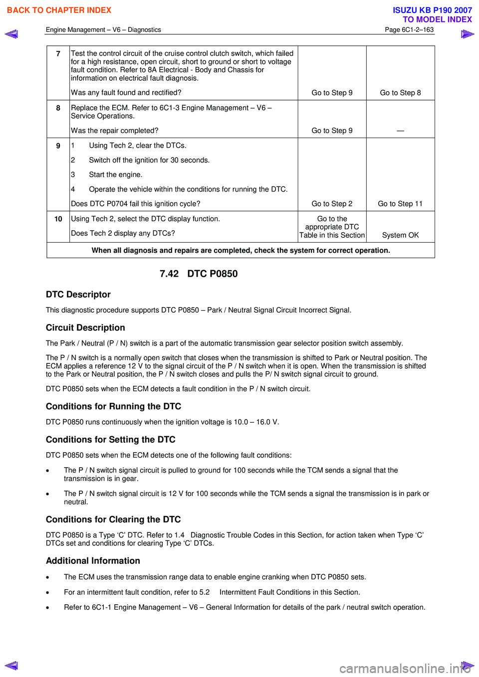
Engine Management – V6 – Diagnostics Page 6C1-2–163
7 Test the control circuit of the cruise control clutch switch, which failed
for a high resistance, open circuit, short to ground or short to voltage
fault condition. Refer to 8A Electrical - Body and Chassis for
information on electrical fault diagnosis.
W as any fault found and rectified? Go to Step 9 Go to Step 8
8 Replace the ECM. Refer to 6C1-3 Engine Management – V6 –
Service Operations.
W as the repair completed? Go to Step 9 —
9 1 Using Tech 2, clear the DTCs.
2 Switch off the ignition for 30 seconds.
3 Start the engine.
4 Operate the vehicle within the conditions for running the DTC.
Does DTC P0704 fail this ignition cycle? Go to Step 2 Go to Step 11
10 Using Tech 2, select the DTC display function.
Does Tech 2 display any DTCs? Go to the
appropriate DTC
Table in this Section System OK
When all diagnosis and repairs are completed, check the system for correct operation.
7.42 DTC P0850
DTC Descriptor
This diagnostic procedure supports DTC P0850 – Park / Neutral Signal Circuit Incorrect Signal.
Circuit Description
The Park / Neutral (P / N) switch is a part of the automatic transmission gear selector position switch assembly.
The P / N switch is a normally open switch that closes when the transmission is shifted to Park or Neutral position. The
ECM applies a reference 12 V to the signal circuit of the P / N switch when it is open. W hen the transmission is shifted
to the Park or Neutral position, the P / N switch closes and pulls the P/ N switch signal circuit to ground.
DTC P0850 sets when the ECM detects a fault condition in the P / N switch circuit.
Conditions for Running the DTC
DTC P0850 runs continuously when the ignition voltage is 10.0 – 16.0 V.
Conditions for Setting the DTC
DTC P0850 sets when the ECM detects one of the following fault conditions:
• The P / N switch signal circuit is pulled to ground for 100 seconds while the TCM sends a signal that the
transmission is in gear.
• The P / N switch signal circuit is 12 V for 100 seconds while the TCM sends a signal the transmission is in park or
neutral.
Conditions for Clearing the DTC
DTC P0850 is a Type ‘C’ DTC. Refer to 1.4 Diagnostic Trouble Codes in this Section, for action taken when Type ‘C’
DTCs set and conditions for clearing Type ‘C’ DTCs.
Additional Information
• The ECM uses the transmission range data to enable engine cranking when DTC P0850 sets.
• For an intermittent fault condition, refer to 5.2 Intermittent Fault Conditions in this Section.
• Refer to 6C1-1 Engine Management – V6 – General Information for details of the park / neutral switch operation.
BACK TO CHAPTER INDEX
TO MODEL INDEX
ISUZU KB P190 2007
Page 3442 of 6020
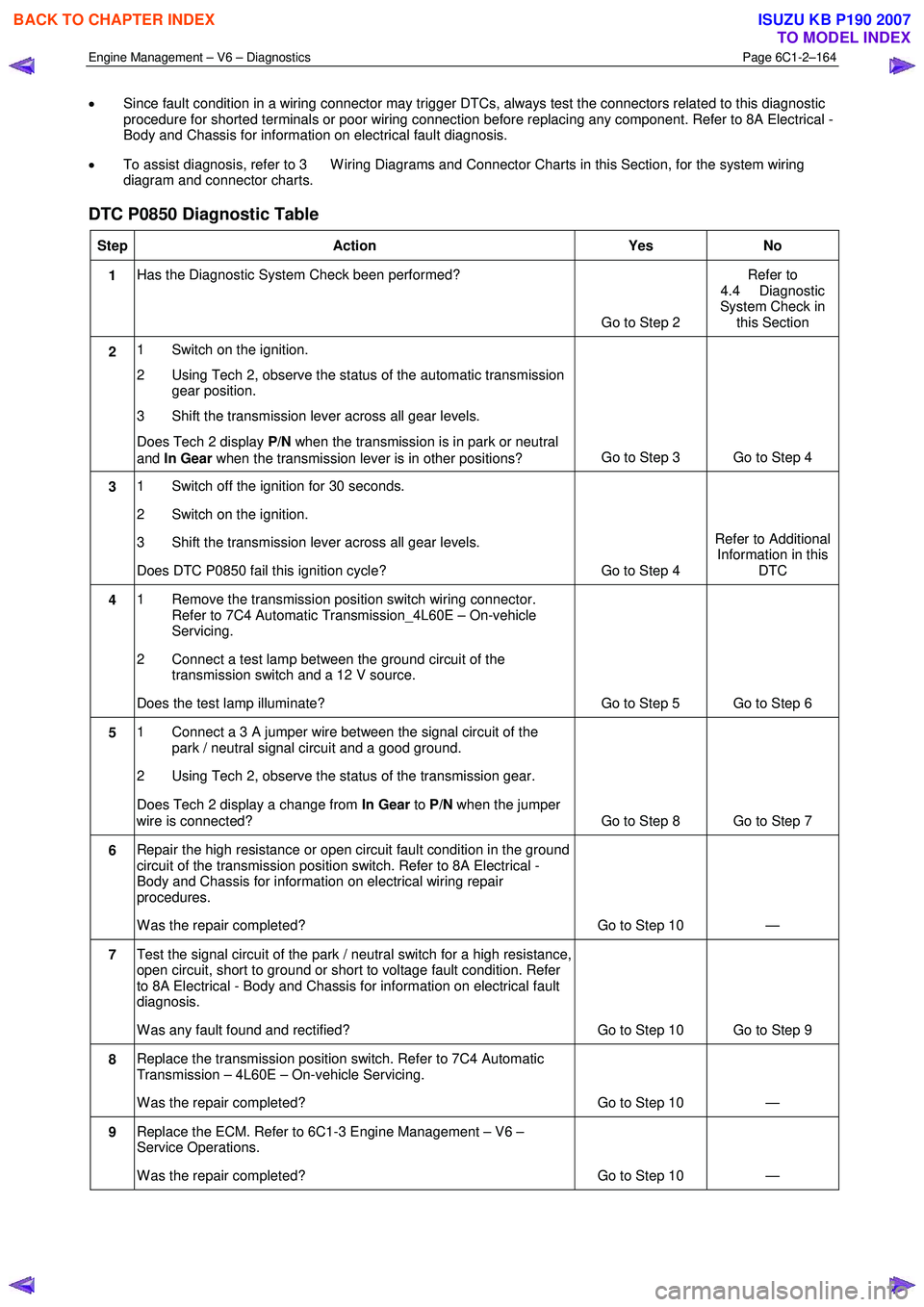
Engine Management – V6 – Diagnostics Page 6C1-2–164
• Since fault condition in a wiring connector may trigger DTCs, always test the connectors related to this diagnostic
procedure for shorted terminals or poor wiring connection before replacing any component. Refer to 8A Electrical -
Body and Chassis for information on electrical fault diagnosis.
• To assist diagnosis, refer to 3 W iring Diagrams and Connector Charts in this Section, for the system wiring
diagram and connector charts.
DTC P0850 Diagnostic Table
Step Action Yes No
1 Has the Diagnostic System Check been performed?
Go to Step 2 Refer to
4.4 Diagnostic
System Check in this Section
2 1 Switch on the ignition.
2 Using Tech 2, observe the status of the automatic transmission gear position.
3 Shift the transmission lever across all gear levels.
Does Tech 2 display P/N when the transmission is in park or neutral
and In Gear when the transmission lever is in other positions? Go to Step 3 Go to Step 4
3
1 Switch off the ignition for 30 seconds.
2 Switch on the ignition.
3 Shift the transmission lever across all gear levels.
Does DTC P0850 fail this ignition cycle? Go to Step 4 Refer to Additional
Information in this DTC
4 1 Remove the transmission position switch wiring connector.
Refer to 7C4 Automatic Transmission_4L60E – On-vehicle
Servicing.
2 Connect a test lamp between the ground circuit of the transmission switch and a 12 V source.
Does the test lamp illuminate? Go to Step 5 Go to Step 6
5 1 Connect a 3 A jumper wire between the signal circuit of the
park / neutral signal circuit and a good ground.
2 Using Tech 2, observe the status of the transmission gear.
Does Tech 2 display a change from In Gear to P/N when the jumper
wire is connected? Go to Step 8 Go to Step 7
6 Repair the high resistance or open circuit fault condition in the ground
circuit of the transmission position switch. Refer to 8A Electrical -
Body and Chassis for information on electrical wiring repair
procedures.
W as the repair completed? Go to Step 10 —
7 Test the signal circuit of the park / neutral switch for a high resistance,
open circuit, short to ground or short to voltage fault condition. Refer
to 8A Electrical - Body and Chassis for information on electrical fault
diagnosis.
W as any fault found and rectified? Go to Step 10 Go to Step 9
8 Replace the transmission position switch. Refer to 7C4 Automatic
Transmission – 4L60E – On-vehicle Servicing.
W as the repair completed? Go to Step 10 —
9 Replace the ECM. Refer to 6C1-3 Engine Management – V6 –
Service Operations.
W as the repair completed? Go to Step 10 —
BACK TO CHAPTER INDEX
TO MODEL INDEX
ISUZU KB P190 2007
Page 3513 of 6020
Engine Management – V6 – Diagnostics Page 6C1-2–235
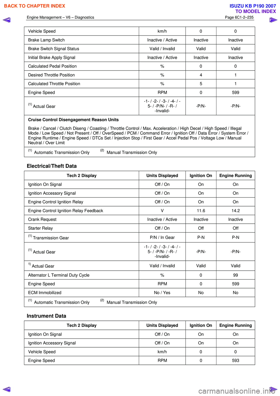
Vehicle Speed km/h 0 0
Brake Lamp Switch Inactive / Active Inactive Inactive
Brake Switch Signal Status Valid / Invalid Valid Valid
Initial Brake Apply Signal Inactive / Active Inactive Inactive
Calculated Pedal Position % 0 0
Desired Throttle Position % 4 1
Calculated Throttle Position % 5 1
Engine Speed RPM 0 599
(1) Actual Gear -1- / -2- / -3- / -4- / -
5- / -P/N- / -R- / -Invalid- -P/N- -P/N-
Cruise Control Disengagement Reason Units
Brake / Cancel / Clutch Diseng / Coasting / Throttle Control / Max. Acceleration / High Decel / High Speed / Illegal
Mode / Low Speed / Not Present / Off / OverSpeed / PCM / Command Error / Ignition Off / Data Error / System Error /
Engine Runtime / Engine Speed / DTCs Set / Injection Stop / First Gear / Accel Pedal Pos / Voltage Low / Manual
Neutral / Over Limit
(1) Automatic Transmission Only (2) Manual Transmission Only
Electrical/Theft Data
Tech 2 Display Units Displayed Ignition On Engine Running
Ignition On Signal Off / On On On
Ignition Accessory Signal Off / On On On
Engine Control Ignition Relay Off / On On On
Engine Control Ignition Relay Feedback V 11.6 14.2
Crank Request Inactive / Active Inactive Inactive
Starter Relay Off / On Off Off
(1) Transmission Gear P/N / In Gear P-N P-N
(1) Actual Gear -1- / -2- / -3- / -4- / -
5- / -P/N- / -R- / -Invalid- -P/N- -P/N-
1) Actual Gear
Valid / Invalid Valid
Valid
Alternator L Terminal Duty Cycle % 0 99
Engine Speed RPM 0 599
ECM Immobilized No / Yes No No
(1) Automatic Transmission Only (2) Manual Transmission Only
Instrument Data
Tech 2 Display Units Displayed Ignition On Engine Running
Ignition On Signal Off / On On On
Ignition Accessory Signal Off / On On On
Vehicle Speed km/h 0 0
Engine Speed RPM 0 593
BACK TO CHAPTER INDEX
TO MODEL INDEX
ISUZU KB P190 2007
Page 3523 of 6020
Engine Management – V6 – Diagnostics Page 6C1-2–245
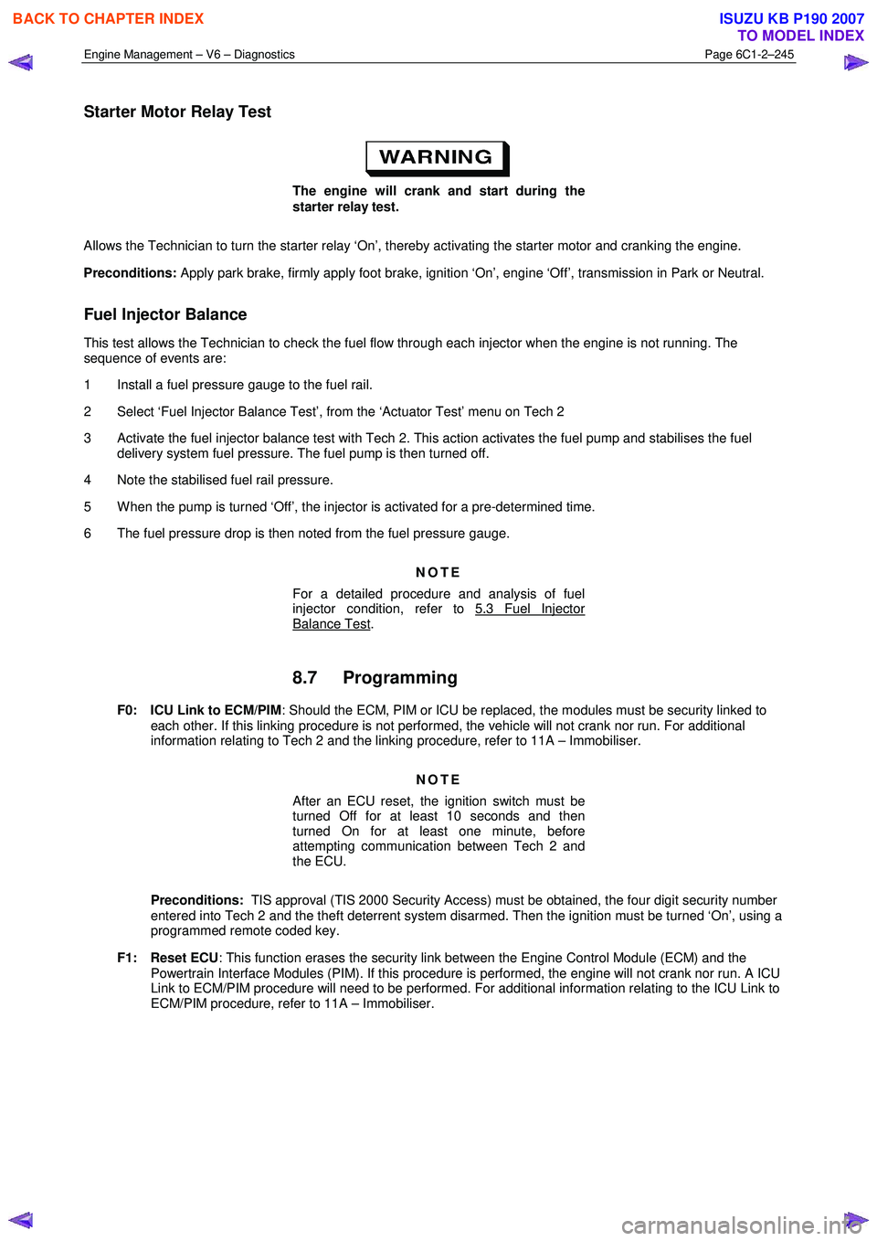
Starter Motor Relay Test
The engine will crank and start during the
starter relay test.
Allows the Technician to turn the starter relay ‘On’, thereby activating the starter motor and cranking the engine.
Preconditions: Apply park brake, firmly apply foot brake, ignition ‘On’, engine ‘Off’, transmission in Park or Neutral.
Fuel Injector Balance
This test allows the Technician to check the fuel flow through each injector when the engine is not running. The
sequence of events are:
1 Install a fuel pressure gauge to the fuel rail.
2 Select ‘Fuel Injector Balance Test’, from the ‘Actuator Test’ menu on Tech 2
3 Activate the fuel injector balance test with Tech 2. This action activates the fuel pump and stabilises the fuel delivery system fuel pressure. The fuel pump is then turned off.
4 Note the stabilised fuel rail pressure.
5 W hen the pump is turned ‘Off’, the injector is activated for a pre-determined time.
6 The fuel pressure drop is then noted from the fuel pressure gauge.
NOTE
For a detailed procedure and analysis of fuel
injector condition, refer to 5.3 Fuel Injector
Balance Test.
8.7 Programming
F0: ICU Link to ECM/PIM : Should the ECM, PIM or ICU be replaced, the modules must be security linked to
each other. If this linking procedure is not performed, the vehicle will not crank nor run. For additional
information relating to Tech 2 and the linking procedure, refer to 11A – Immobiliser.
NOTE
After an ECU reset, the ignition switch must be
turned Off for at least 10 seconds and then
turned On for at least one minute, before
attempting communication between Tech 2 and
the ECU.
Preconditions: TIS approval (TIS 2000 Security Access) must be obtained, the four digit security number
entered into Tech 2 and the theft deterrent system disarmed. Then the ignition must be turned ‘On’, using a
programmed remote coded key.
F1: Reset ECU : This function erases the security link between the Engine Control Module (ECM) and the
Powertrain Interface Modules (PIM). If this procedure is performed, the engine will not crank nor run. A ICU
Link to ECM/PIM procedure will need to be performed. For additional information relating to the ICU Link to
ECM/PIM procedure, refer to 11A – Immobiliser.
BACK TO CHAPTER INDEX
TO MODEL INDEX
ISUZU KB P190 2007