2007 ISUZU KB P190 Neutral switch
[x] Cancel search: Neutral switchPage 3819 of 6020
Automatic Transmission – 4L60E – Electrical Diagnosis Page 7C2–33
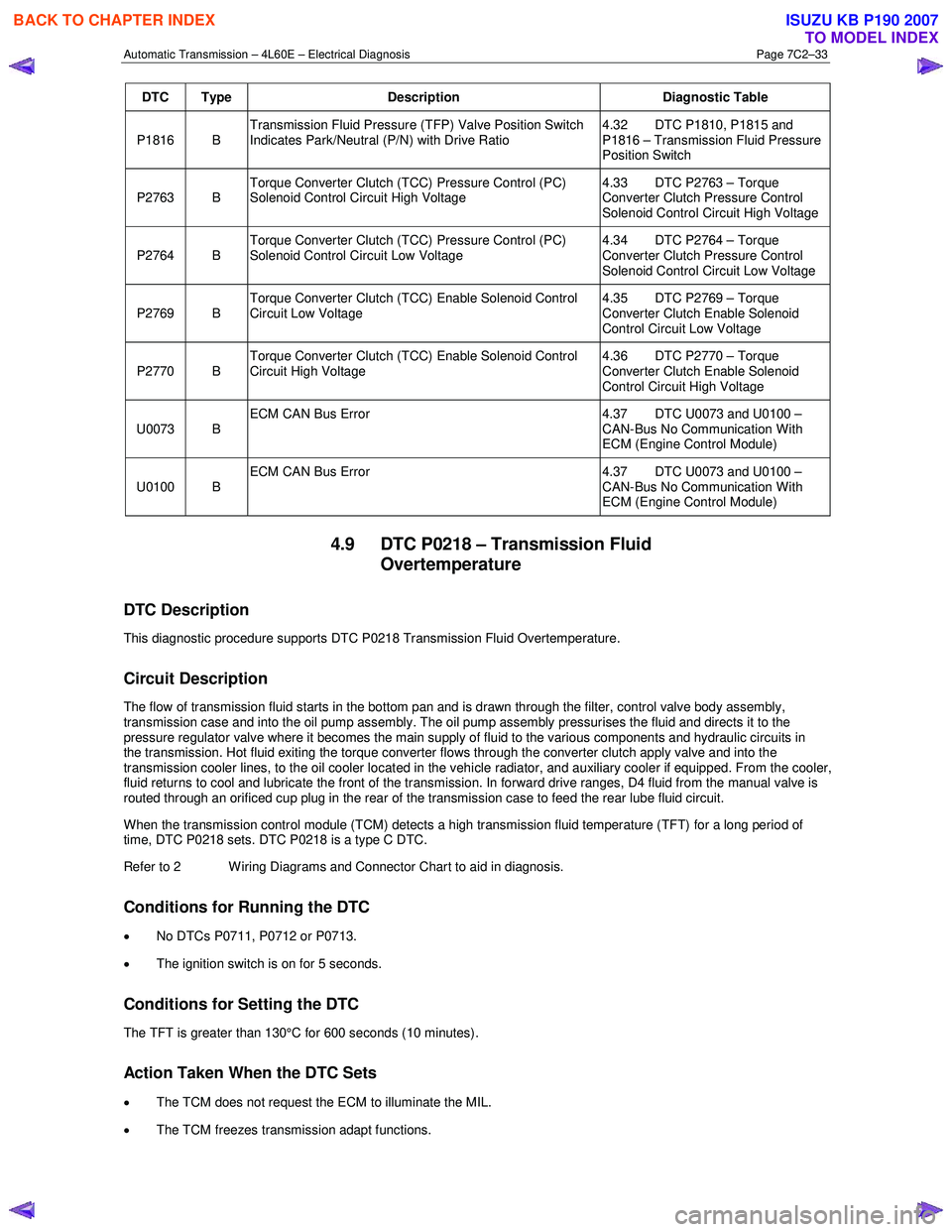
DTC Type Description Diagnostic Table
P1816 B Transmission Fluid Pressure (TFP) Valve Position Switch
Indicates Park/Neutral (P/N) with Drive Ratio 4.32 DTC P1810, P1815 and
P1816 – Transmission Fluid Pressure
Position Switch
P2763 B Torque Converter Clutch (TCC) Pressure Control (PC)
Solenoid Control Circuit High Voltage 4.33 DTC P2763 – Torque
Converter Clutch Pressure Control
Solenoid Control Circuit High Voltage
P2764 B Torque Converter Clutch (TCC) Pressure Control (PC)
Solenoid Control Circuit Low Voltage 4.34 DTC P2764 – Torque
Converter Clutch Pressure Control
Solenoid Control Circuit Low Voltage
P2769 B Torque Converter Clutch (TCC) Enable Solenoid Control
Circuit Low Voltage 4.35 DTC P2769 – Torque
Converter Clutch Enable Solenoid
Control Circuit Low Voltage
P2770 B Torque Converter Clutch (TCC) Enable Solenoid Control
Circuit High Voltage 4.36 DTC P2770 – Torque
Converter Clutch Enable Solenoid
Control Circuit High Voltage
U0073 B ECM CAN Bus Error
4.37 DTC U0073 and U0100 –
CAN-Bus No Communication With
ECM (Engine Control Module)
U0100 B ECM CAN Bus Error
4.37 DTC U0073 and U0100 –
CAN-Bus No Communication With
ECM (Engine Control Module)
4.9 DTC P0218 – Transmission Fluid Overtemperature
DTC Description
This diagnostic procedure supports DTC P0218 Transmission Fluid Overtemperature.
Circuit Description
The flow of transmission fluid starts in the bottom pan and is drawn through the filter, control valve body assembly,
transmission case and into the oil pump assembly. The oil pump assembly pressurises the fluid and directs it to the
pressure regulator valve where it becomes the main supply of fluid to the various components and hydraulic circuits in
the transmission. Hot fluid exiting the torque converter flows through the converter clutch apply valve and into the
transmission cooler lines, to the oil cooler located in the vehicle radiator, and auxiliary cooler if equipped. From the cooler ,
fluid returns to cool and lubricate the front of the transmission. In forward drive ranges, D4 fluid from the manual valve is
routed through an orificed cup plug in the rear of the transmission case to feed the rear lube fluid circuit.
When the transmission control module (TCM) detects a high transmission fluid temperature (TFT) for a long period of
time, DTC P0218 sets. DTC P0218 is a type C DTC.
Refer to 2 W iring Diagrams and Connector Chart to aid in diagnosis.
Conditions for Running the DTC
• No DTCs P0711, P0712 or P0713.
• The ignition switch is on for 5 seconds.
Conditions for Setting the DTC
The TFT is greater than 130°C for 600 seconds (10 minutes).
Action Taken When the DTC Sets
•
The TCM does not request the ECM to illuminate the MIL.
• The TCM freezes transmission adapt functions.
BACK TO CHAPTER INDEX
TO MODEL INDEX
ISUZU KB P190 2007
Page 3889 of 6020
Automatic Transmission – 4L60E – Electrical Diagnosis Page 7C2–103
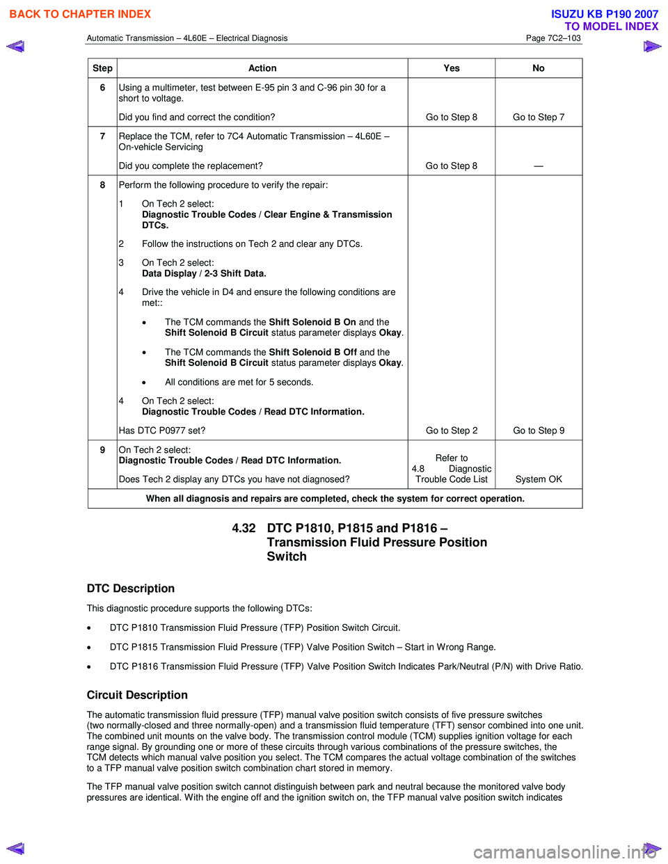
Step Action Yes No
6 Using a multimeter, test between E-95 pin 3 and C-96 pin 30 for a
short to voltage.
Did you find and correct the condition? Go to Step 8 Go to Step 7
7 Replace the TCM, refer to 7C4 Automatic Transmission – 4L60E –
On-vehicle Servicing
Did you complete the replacement? Go to Step 8 —
8 Perform the following procedure to verify the repair:
1 On Tech 2 select: Diagnostic Trouble Codes / Clear Engine & Transmission
DTCs.
2 Follow the instructions on Tech 2 and clear any DTCs.
3 On Tech 2 select: Data Display / 2-3 Shift Data.
4 Drive the vehicle in D4 and ensure the following conditions are met::
• The TCM commands the Shift Solenoid B On and the
Shift Solenoid B Circuit status parameter displays Okay.
• The TCM commands the Shift Solenoid B Off and the
Shift Solenoid B Circuit status parameter displays Okay.
• All conditions are met for 5 seconds.
4 On Tech 2 select:
Diagnostic Trouble Codes / Read DTC Information.
Has DTC P0977 set? Go to Step 2 Go to Step 9
9 On Tech 2 select:
Diagnostic Trouble Codes / Read DTC Information.
Does Tech 2 display any DTCs you have not diagnosed? Refer to
4.8 Diagnostic Trouble Code List System OK
When all diagnosis and repairs are completed, check the
system for correct operation.
4.32 DTC P1810, P1815 and P1816 –
Transmission Fluid Pressure Position
Switch
DTC Description
This diagnostic procedure supports the following DTCs:
• DTC P1810 Transmission Fluid Pressure (TFP) Position Switch Circuit.
• DTC P1815 Transmission Fluid Pressure (TFP) Valve Position Switch – Start in W rong Range.
• DTC P1816 Transmission Fluid Pressure (TFP) Valve Position Switch Indicates Park/Neutral (P/N) with Drive Ratio.
Circuit Description
The automatic transmission fluid pressure (TFP) manual valve position switch consists of five pressure switches
(two normally-closed and three normally-open) and a transmission fluid temperature (TFT) sensor combined into one unit.
The combined unit mounts on the valve body. The transmission control module (TCM) supplies ignition voltage for each
range signal. By grounding one or more of these circuits through various combinations of the pressure switches, the
TCM detects which manual valve position you select. The TCM compares the actual voltage combination of the switches
to a TFP manual valve position switch combination chart stored in memory.
The TFP manual valve position switch cannot distinguish between park and neutral because the monitored valve body
pressures are identical. W ith the engine off and the ignition switch on, the TFP manual valve position switch indicates
BACK TO CHAPTER INDEX
TO MODEL INDEX
ISUZU KB P190 2007
Page 3890 of 6020
Automatic Transmission – 4L60E – Electrical Diagnosis Page 7C2–104
park/neutral. Disconnecting connector E-95 from the transmission removes the ground potential for the three range
signals to the TCM. In this case, with the engine off, and the ignition switch on, D2 will be indicated.
When the TCM detects an invalid state of the TFP manual valve position switch circuit by deciphering the TFP manual
valve position switch inputs, then either DTC P1810, P1815 or P1816 sets. All theses DTCs are a type B DTC.
Refer to 2 W iring Diagrams and Connector Chart to aid in diagnosis.
Conditions for Running the DTC
DTC P1810
• The system voltage is 8 – 18 V.
• The engine speed is greater than 500 r.p.m. for 5 seconds.
DTC P1815
•
No DTCs P0722 or P0723.
• The system voltage is 8 – 18 V.
• The engine speed is less than 50 r.p.m., then 50 – 650 r.p.m. for 0.75 seconds, then greater than 650 r.p.m. for
5 seconds.
• Output shaft speed less than 250 r.p.m.
DTC P1816
• No DTCs P0722 or P0723.
• The system voltage is 8 – 18 V.
• The engine speed is less than 50 r.p.m., then 50 – 650 r.p.m. for 0.75 seconds, then greater than 650 r.p.m. for
5 seconds.
• Output shaft speed less than 250 r.p.m.
Conditions for Setting the DTC
DTC P1810
DTC P1810 sets when the TCM detects an invalid TFP manual valve position switch state for 60 seconds.
DTC P1815
DTC P1815 sets when the TCM detects D2 only, TFP manual valve position switch state after engine start for 7 seconds.
DTC P1816
DTC P1816 sets when the TCM detects one of the following conditions for 13 seconds:
• park/neutral indicated with a 1st gear ratio,
• park/neutral indicated with a 2nd gear ratio,
• park/neutral indicated with a 3rd gear ratio, or
• park/neutral indicated with a 4th gear ratio.
Action Taken When the DTC Sets
• The TCM requests the ECM to illuminate the MIL during the second consecutive trip in which the conditions for
setting the DTC are met.
• The TCM commands maximum line pressure.
• The TCM freezes transmission adaptive functions.
• The TCM inhibits TCC engagement.
BACK TO CHAPTER INDEX
TO MODEL INDEX
ISUZU KB P190 2007
Page 3911 of 6020
Automatic Transmission – 4L60E – Electrical Diagnosis Page 7C2–125
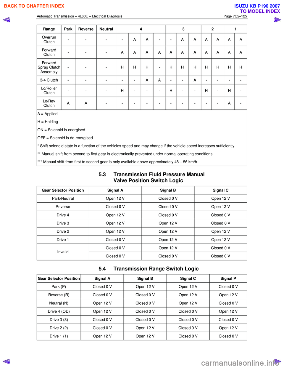
Range Park Reverse Neutral 4 3 2 1
Overrun
Clutch - - - - A A - - A A A A A A
Forward
Clutch - - - A A A A A A A A A A A
Forward
Sprag Clutch Assembly - - - H H H - H H H H H H H
3-4 Clutch - - - - - A A - - A - - - -
Lo/Roller
Clutch - - - H - - - H - - H - H -
Lo/Rev
Clutch A A - - - - - - - - - - A -
A = Applied
H = Holding
ON = Solenoid is energised
OFF = Solenoid is de-energised
* Shift solenoid state is a function of the vehicles speed and may change if the vehicle speed increases sufficiently
** Manual shift from second to first gear is electronically prevented under normal operating conditions
*** Manual shift from first to second gear is only available above approximately 48 – 56 km/h
5.3 Transmission Fluid Pressure Manual Valve Position Switch Logic
Gear Selector Position Signal A Signal B Signal C
Park/Neutral Open 12 V Closed 0 V Open 12 V
Reverse Closed 0 V Closed 0 V Open 12 V
Drive 4 Open 12 V Closed 0 V Closed 0 V
Drive 3 Open 12 V Open 12 V Closed 0 V
Drive 2 Open 12 V Open 12 V Open 12 V
Drive 1 Closed 0 V Open 12 V Open 12 V
Closed 0 V Open 12 V Closed 0 V Invalid
Closed 0 V Closed 0 V Closed 0 V
5.4 Transmission Range Switch Logic
Gear Selector Position Signal A Signal B Signal C Signal P
Park (P) Closed 0 V Open 12 V Open 12 V Closed 0 V
Reverse (R) Closed 0 V Closed 0 V Open 12 V Open 12 V
Neutral (N) Open 12 V Closed 0 V Open 12 V Closed 0 V
Drive 4 (OD) Open 12 V Closed 0 V Closed 0 V Open 12 V
Drive 3 (3) Closed 0 V Closed 0 V Closed 0 V Closed 0 V
Drive 2 (2) Closed 0 V Open 12 V Closed 0 V Open 12 V
Drive 1 (1) Open 12 V Open 12 V Closed 0 V Closed 0 V
BACK TO CHAPTER INDEX
TO MODEL INDEX
ISUZU KB P190 2007
Page 3914 of 6020
Automatic Transmission – 4L60E – On-vehicle Servicing Page 7C4–1
7C4
Automatic Transmission – 4L60E –
On-vehicle Servicing
ATTENTION
Before performing any service operation or other procedure described in this Section, refer to General Information Warnings, Cautions and Notes for correct workshop practices with regard to safety and/or property damage.
1 General Information ............................................................................................................ ...................3
1.1 General Service Information ................................................................................................................................. 3
Description ............................................................................................................................................................. 3
Service Information ............................................................................................................ ................................... 3
1.2 WARNINGS, CAUTIONS and NOTES................................................................................................... ................. 3
Definition of WARNING, CAUTION and NOTE Statements ............................................................................. .... 3
WARNING Defined............................................................................................................................................. 4
CAUTION Defined .............................................................................................................................................. 4
NOTE Defined .................................................................................................................................................... 4
2 Maintenance Operations......................................................................................................... ...............5
2.1 Transmission Fluid ................................................................................................................................................ 5
Transmission Fluid Colour...................................................................................................... .............................. 5
Transmission Fluid Level ...................................................................................................................................... 5
2.2 Reverse Flush and Flow Rate Test ............................................................................................... ........................ 6
Reverse Flush ........................................................................................................................................................ 6
Flow Rate Test........................................................................................................................................................ 7
3 Service Operations ............................................................................................................. ....................8
3.1 Fluid Change and Filter Replacement ............................................................................................ ...................... 8
Remove ................................................................................................................................................................... 8
Reinstall .................................................................................................................................................................. 9
3.2 Shift Selector Assembly ...................................................................................................................................... 11
Remove ................................................................................................................................................................. 11
Reinstall ................................................................................................................................................................ 12
3.3 Selector Cable Assembly .................................................................................................................................... 14
Remove ................................................................................................................................................................. 15
Reinstall ................................................................................................................................................................ 15
3.4 Neutral Start and Back-up Lamp Switch ............................................................................................................ 16
Remove ................................................................................................................................................................. 16
Reinstall ................................................................................................................................................................ 17
Adjust .................................................................................................................................................................... 17
3.5 Vehicle Speed Sensor ......................................................................................................................................... 18
Remove ................................................................................................................................................................. 18
Reinstall ................................................................................................................................................................ 19
3.6 Manual Shaft Oil Seal .......................................................................................................................................... 19
Replace ................................................................................................................................................................. 19
3.7 Transmission Support and Mount ................................................................................................. ..................... 20
Remove ................................................................................................................................................................. 20
Reinstall ................................................................................................................................................................ 21
3.8 Extension Housing Oil Seal, RWD ...................................................................................................................... 22
Replace ................................................................................................................................................................. 22
3.9 Extension Housing and Rear Bush, RWD ........................................................................................... ............... 22
BACK TO CHAPTER INDEX
TO MODEL INDEX
ISUZU KB P190 2007
Page 3916 of 6020
Automatic Transmission – 4L60E – On-vehicle Servicing Page 7C4–3
1 General Information
This Section describes the removal and reinstallation procedures of the four speed 4L60E hydra-matic automatic
transmission as well as the service operations which can be performed with the transmission still fitted to the vehicle.
1.1 General Service Information
Description
The shift selector mechanism is linked to the transmission manual shaft with a selector cable. A heat protector is fitted
over the neutral start and back-up switch and manual shaft select lever.
For rear wheel drive (RWD) vehicles an extension housing is fitted to the rear of the transmission case.
Four wheel drive (4W D) vehicles have an adaptor housing and transfer case fitted to the rear of the transmission case,
for description and service operation refer to 7D Transfer Case and Adaptor Housing.
The four speed 4L60E hydra-matic automatic transmission is fitted with a filler tube, a breather hose and a vent pipe for
hot fluid overflow.
The transmission fluid is driven through a cooler within the radiator via the cooler line/hose assemblies to maintain
normal operating temperature.
Service Information
Throughout the service operations within this
Section, when handling retaining clips, using
compressed air or cleaning fluids, wear safety
equipment to avoid personal injury.
Refer to 7C1 Automatic Transmission – 4L60E – General Information for the following:
• information relating to mechanical and electrical operations,
• abbreviations, transmission specifications, special tools and torque wrench specifications,
• servicing, cleaning and inspection procedure recommendations.
It is essential to read and understand the General Information, W arnings, Cautions and Service Notes contained in that
same Section, before any service operation is performed on the four speed 4L60E hydra-matic automatic transmission or
any associated components.
Failure to comply with the procedures and service notes can affect the reliable and efficient operation of this automatic
transmission.
1.2 WARNINGS, CAUTIONS and NOTES
This Section contains various W ARNINGS, CAUTIONS and NOTE statements that you must observe carefully to reduce
the risk of death or injury during service, repair procedures or vehicle operation. Incorrect service or repair procedures
may damage the vehicle or cause operational faults. W ARNINGS, CAUTION and NOTE statements are not exhaustive.
GM HOLDEN LTD can not possibly warn of all the potentially hazardous consequences of failure to follow these
instructions.
Definition of WARNING, CAUTION and NOTE Statements
Diagnosis and repair procedures in this Section contain both general and specific W ARNING, CAUTION and NOTE
statements. GM HOLDEN LTD is dedicated to the presentation of service information that helps the technician to
diagnose and repair the systems necessary for proper operation of the vehicle. Certain procedures may present a hazard
to the technician if they are not followed in the recommended manner. W ARNING, CAUTION and NOTE statements are
designed to help prevent these hazards from occurring, but not all hazards can be foreseen.
BACK TO CHAPTER INDEX
TO MODEL INDEX
ISUZU KB P190 2007
Page 3929 of 6020
Automatic Transmission – 4L60E – On-vehicle Servicing Page 7C4–16
8 Slide the cover (3) in the direction shown by the
arrow (1).
9 Using a small flat blade screwdriver, move the lock piece (4) from the position indicated by the arrow (2).
Continue to move the lock piece until the adjuster (5)
position begins to change.
Figure 7C4 – 12
10 Connect the selector cable to the transmission external manual shaft linkage.
11 Insert the lock piece in the adjuster to engage with the serrated cable end (cable length adjustment).
12 Slide the cover (1) on the adjuster and secure the lock piece.
Figure 7C4 – 13
13 Install the heat shield (7) and tighten the attaching screws (1 and 6) to the correct torque specification, refer to Figure 7C4 – 10.
Heat shield front attaching screw
torque specification ............................................ 25.0 Nm
Heat shield rear attaching screw torque specification ..............................................9.0 Nm
14 Move the selector lever to the P position and press the selector lever knob button five times.
15 Ensure the selector lever moves smoothly to each of its positions.
16 Check if the shift position indicated by the selector lever and the actual shift position are the same, rectify if required.
17 Lower the vehicle to the ground. Ensure the engine can only be started with the transmission selector lever in Park or Neutral position and the back-up lamps work correctly. If required, adjust the neutral start and back-up lamp
switch, refer to 3.4 Neutral Start and Back-up Lamp Switch.
18 Ensure the gear selection operates correctly.
19 Install the front and rear console, refer to 10 Cab.
3.4 Neutral Start and Back-up Lamp Switch
Remove
1 Position the transmission selector lever to the P position.
2 Raise the vehicle and support in a safe manner, refer to 0A General Information for the location of support points.
BACK TO CHAPTER INDEX
TO MODEL INDEX
ISUZU KB P190 2007
Page 3930 of 6020

Automatic Transmission – 4L60E – On-vehicle Servicing Page 7C4–17
3 Remove the three attaching screws (1 and 2) and the
heat shield (3).
4 Hold the transmission manual shaft linkage (4) with an adjustable wrench and remove the linkage attaching
nut (5).
5 Carefully remove the manual shaft linkage and selector cable from the transmission manual shaft (6).
6 Prise the connector position assurance (CPA) securing pin (7) from the neutral start and back-up
lamp switch (8) taking care not to break the pin in the
process. Disconnect the connector (9) from the switch
assembly by pulling down the release bar (10).
NOTE
The connector will automatically disconnect at
the same time the release bar is withdrawn.
7 Remove the attaching screw (11) and slide the switch assembly over the transmission manual shaft to
remove it.
Figure 7C4 – 14
Reinstall
1 Slide the neutral start and back-up lamp switch (8) over the transmission manual shaft (6) and reinstall the two
attaching screws (1 and 11), tighten them finger tight until the adjustment process has been completed, refer to
Figure 7C4 – 14.
2 Install the manual shaft linkage (4) and the attaching nut (5). Hold the linkage with an adjustable wrench and tighten the nut to the correct torque specification.
Manual shaft linkage attaching nut
torque specification ............................................ 25.0 Nm
3 Install the connector (9) but do not reinsert the CPA securing pin (7) at this stage.
4 Check the shift selector linkage operation and adjust as required, refer to 3.2 Shift Selector Assembly.
5 Check and adjust as required the neutral start and back-up lamp switch as described in this Section, refer to Adjust.
Adjust
1 Raise the vehicle and support in a safe manner, refer to 0A General Information for the location of support points.
2 If required, loosen the neutral start and back-up lamp switch (8) as follows, refer to Figure 7C4 – 14: a Remove the three attaching screws (1 and 2) and the heat shield (3).
b Prise the connector position assurance (CPA) securing pin (7) from the neutral start and back-up lamp switch taking care not to break the pin in the process.
c Disconnect connector (9) from the switch assembly by pulling down the release bar (10).
NOTE
The connector will automatically disconnect at the
same time the release bar is withdrawn.
d Loosen the screw (11) attaching the switch and refit the front screw (1) keep them finger tight.
e Reinstall the connector (9) but do not reinsert the CPA securing pin at this stage.
3 Rotate the neutral start and back-up lamp switch back and forth until a central position is attained and then lightly tighten the front screw (1) to prevent the switch from rotating.
BACK TO CHAPTER INDEX
TO MODEL INDEX
ISUZU KB P190 2007