Page 1076 of 6020

6E-42 Engine Control System (4JH1)
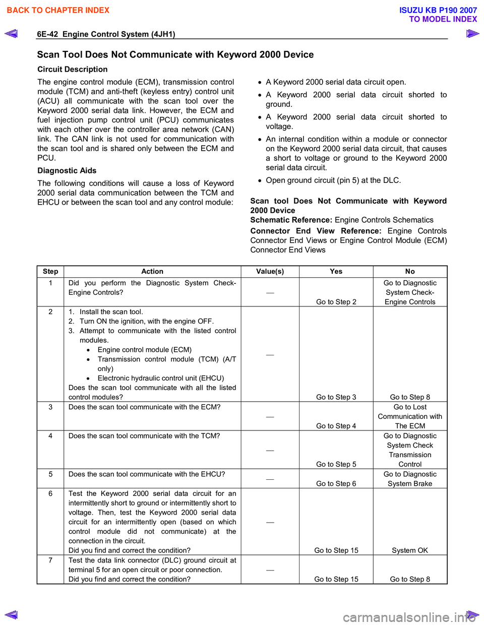
Scan Tool Does Not Communicate with Keyword 2000 Device
Circuit Description
The engine control module (ECM), transmission control
module (TCM) and anti-theft (keyless entry) control unit
(ACU) all communicate with the scan tool over the
Keyword 2000 serial data link. However, the ECM and
fuel injection pump control unit (PCU) communicates
with each other over the controller area network (CAN)
link. The CAN link is not used for communication with
the scan tool and is shared only between the ECM and
PCU.
Diagnostic Aids
The following conditions will cause a loss of Keyword
2000 serial data communication between the TCM and
EHCU or between the scan tool and any control module:
• A Keyword 2000 serial data circuit open.
• A Keyword 2000 serial data circuit shorted to
ground.
• A Keyword 2000 serial data circuit shorted to
voltage.
•
An internal condition within a module or connector
on the Keyword 2000 serial data circuit, that causes
a short to voltage or ground to the Keyword 2000
serial data circuit.
• Open ground circuit (pin 5) at the DLC.
Scan tool Does Not Communicate with Keyword
2000 Device
Schematic Reference: Engine Controls Schematics
Connector End View Reference: Engine Controls
Connector End Views or Engine Control Module (ECM)
Connector End Views
Step Action Value(s) Yes No
1 Did you perform the Diagnostic System Check-
Engine Controls?
Go to Step 2 Go to Diagnostic
System Check-
Engine Controls
2 1. Install the scan tool. 2. Turn ON the ignition, with the engine OFF.
3. Attempt to communicate with the listed control modules. • Engine control module (ECM)
• Transmission control module (TCM) (A/T
only)
• Electronic hydraulic control unit (EHCU)
Does the scan tool communicate with all the listed
control modules?
Go to Step 3 Go to Step 8
3 Does the scan tool communicate with the ECM?
Go to Step 4 Go to Lost
Communication with The ECM
4 Does the scan tool communicate with the TCM?
Go to Step 5 Go to Diagnostic
System Check Transmission Control
5 Does the scan tool communicate with the EHCU?
Go to Step 6 Go to Diagnostic
System Brake
6 Test the Keyword 2000 serial data circuit for an intermittently short to ground or intermittently short to
voltage. Then, test the Keyword 2000 serial data
circuit for an intermittently open (based on which
control module did not communicate) at the
connection in the circuit.
Did you find and correct the condition?
Go to Step 15 System OK
7 Test the data link connector (DLC) ground circuit at terminal 5 for an open circuit or poor connection.
Did you find and correct the condition?
Go to Step 15 Go to Step 8
BACK TO CHAPTER INDEX
TO MODEL INDEX
ISUZU KB P190 2007
Page 4915 of 6020
TRANSFER CONTROL SYSTEM 7D1-41
CONNECTOR LIST
No. Connector face No. Connector face
B13
White
Fan switch B85
W eld splice 7 (Ground)
B23
White
Meter-A B95
White
Keyless entry control unit
B24
White
Meter-B B96
Gray PIM1
B54
White
J/B I2 B97
WhitePIM2
B56
White
J/B I4 C2
SilverEngine room-RH ground
B62
White
Ignition switch (IGSUB: G1) C4
Sky blueFront wiper motor
B63
White
Ignition switch (IGSUB: G2) C5
~
C14 NOT USED
B64
W eld splice 1 (Illumination) C36
SilverEngine room-LH; ground
B65
W eld splice 2 (Ground) C56
(C24SE)
ECM
B66
White
4 ×4 switch C56
(4JH1-TC)
Black
ECM-A
BACK TO CHAPTER INDEX
TO MODEL INDEX
ISUZU KB P190 2007
Page 4941 of 6020

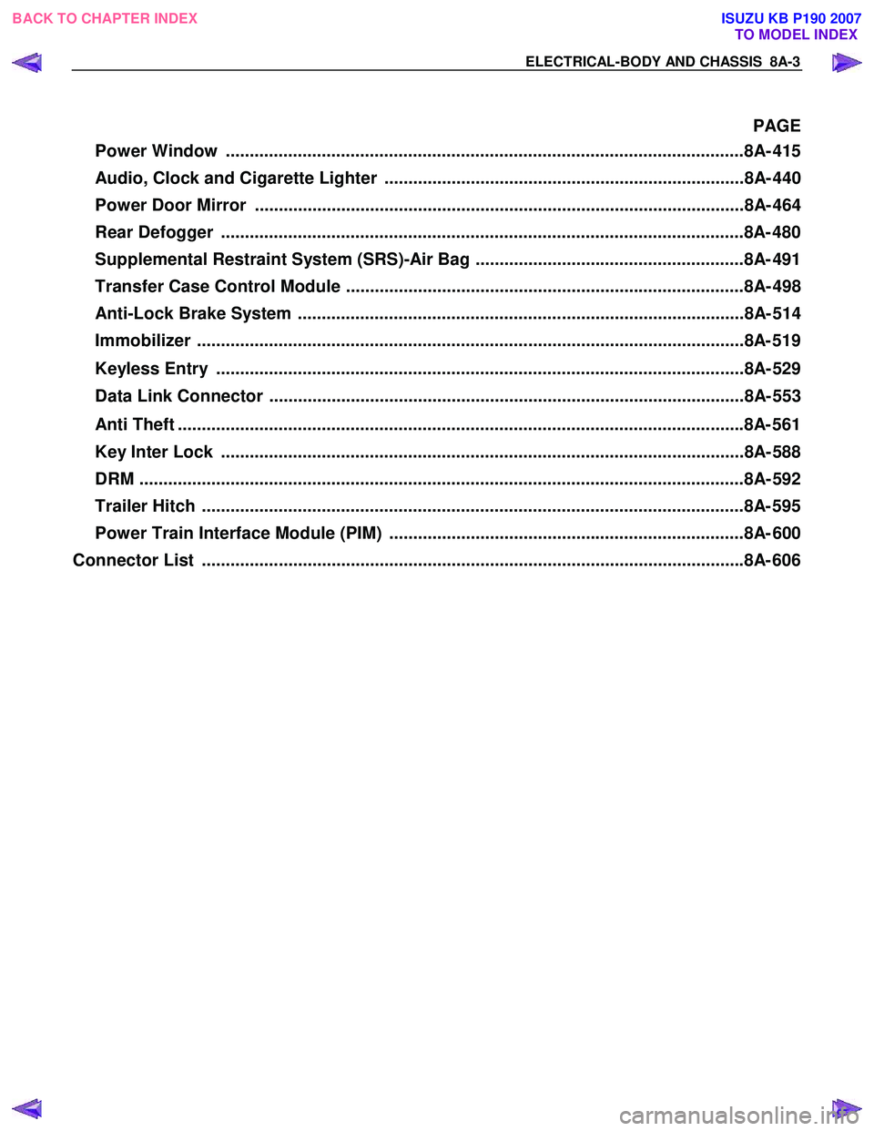
ELECTRICAL-BODY AND CHASSIS 8A-3
PAGE
Power Window ............................................................................................................8A- 41 5
Audio, Clock and Cigarette Lighter ...........................................................................8A- 440
Power Door Mirror ......................................................................................................8A- 464
Rear Defogger .............................................................................................................8A- 480
Supplemental Restraint System (SRS)-Air Bag ........................................................8A- 491
Transfer Case Control Module ...................................................................................8A- 498
Anti-Lock Brake System .............................................................................................8A- 514
Immobilizer ..................................................................................................................8 A- 519
Keyless Entry ..............................................................................................................8A- 529
Data Link Connector ...................................................................................................8A- 553
Anti Theft ..................................................................................................................... .8A- 561
Key Inter Lock .............................................................................................................8A- 588
DRM ........................................................................................................................... ...8A- 592
Trailer Hitch ................................................................................................................. 8A- 595
Power Train Interface Module (PIM) ..........................................................................8A- 600
Connector List ................................................................................................................ .8A- 606
BACK TO CHAPTER INDEX
TO MODEL INDEX
ISUZU KB P190 2007
Page 5187 of 6020
ELECTRICAL-BODY AND CHASSIS 8A-249
CIRCUIT DIAGRAM C24SE (RHD) WITH KEYLESS ENTRY
RTW 780XF012801
BACK TO CHAPTER INDEX TO MODEL INDEXISUZU KB P190 2007
Page 5190 of 6020
8A-252 ELECTRICAL-BODY AND CHASSIS
CIRCUIT DIAGRAM C24SE (LHD) WITH KEYLESS ENTRY
RTW 780XF013001
BACK TO CHAPTER INDEX TO MODEL INDEXISUZU KB P190 2007
Page 5467 of 6020
ELECTRICAL-BODY AND CHASSIS 8A-529
KEYLESS ENTRY
PARTS LOCATION (RHD)
RTW 78AXF041101 & RTW 78AXF047301
BACK TO CHAPTER INDEX TO MODEL INDEXISUZU KB P190 2007
Page 5476 of 6020

8A-538 ELECTRICAL-BODY AND CHASSIS
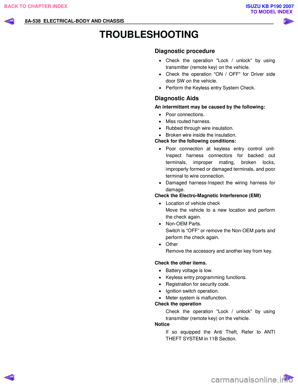
TROUBLESHOOTING
Diagnostic procedure
•
Check the operation "Lock / unlock" by using
transmitter (remote key) on the vehicle.
• Check the operation "ON / OFF" for Driver side
door SW on the vehicle.
• Perform the Keyless entry System Check.
Diagnostic Aids
An intermittent may be caused by the following:
• Poor connections.
• Miss routed harness.
• Rubbed through wire insulation.
• Broken wire inside the insulation.
Check for the following conditions:
• Poor connection at keyless entry control unit-
Inspect harness connectors for backed out
terminals, improper mating, broken locks,
improperly formed or damaged terminals, and poo
r
terminal to wire connection.
• Damaged harness-Inspect the wiring harness fo
r
damage.
Check the Electro-Magnetic Interference (EMI)
• Location of vehicle check
Move the vehicle to a new location and perform
the check again.
• Non-OEM Parts.
Switch is “OFF” or remove the Non-OEM parts and
perform the check again.
• Other
Remove the accessory and another key from key.
Check the other items.
• Battery voltage is low.
• Keyless entry programming functions.
• Registration for security code.
• Ignition switch operation.
• Meter system is malfunction.
Check the operation
Check the operation "Lock / unlock" by using
transmitter (remote key) on the vehicle.
Notice
If so equipped the Anti Theft, Refer to ANTI
THEFT SYSTEM in 11B Section.
BACK TO CHAPTER INDEX TO MODEL INDEXISUZU KB P190 2007
Page 5477 of 6020
ELECTRICAL-BODY AND CHASSIS 8A-539
Keyless Entry System Check
Step Action Value (s) Yes No
1 Check the fuse for the keyless entry power feed
circuit. (EB16 10A)
If a problem found, repair as necessary.
W as the problem found? — Verify repair Go to Step 2
2
1. Check the KCU (Keyless Entry Control Unit)
ground circuit for an open, or short to voltage.
Also, check the KCU ignition feed circuit for an
open or short to ground and the KCU ground
circuit for an open.
2. If a problem is found, repair as necessary.
W as the problem found? — Verify repair Go to Step 3
3
1. Check the front drive side SW circuit for an open,
or short to voltage.
2. If a problem is found, repair as necessary.
W as the problem found? — Verify repair Go to Step 4
4
1. Check the operation "Lock / unlock" by using
transmitter (Remote key) on the vehicle.
W as the problem found? — Go to
Diagnostic Chart Go to
Diagnostic Aids
BACK TO CHAPTER INDEX TO MODEL INDEXISUZU KB P190 2007