2007 ISUZU KB P190 Neutral switch
[x] Cancel search: Neutral switchPage 4133 of 6020
7A3-48 ON-VEHICLE SERVICE (AW30–40LE)
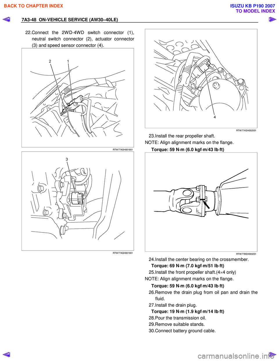
22.Connect the 2W D-4W D switch connector (1),
neutral switch connector (2), actuator connecto
r
(3) and speed sensor connector (4).
RTW 77ASH001801
RTW 77ASH001901
RTW 77ASH002001
23.Install the rear propeller shaft.
NOTE: Align alignment marks on the flange.
Torque: 59 N ⋅
⋅⋅
⋅
m (6.0 kgf ⋅m/43 lb ⋅ft)
RTW 77BSH000201
24.Install the center bearing on the crossmember.
Torque: 69 N ⋅
⋅⋅
⋅
m (7.0 kgf ⋅m/51 lb ⋅ft)
25.Install the front propeller shaft.(4 ×4 only)
NOTE: Align alignment marks on the flange.
Torque: 59 N ⋅
⋅⋅
⋅
m (6.0 kgf ⋅m/43 lb ⋅ft)
26.Remove the drain plug from oil pan and drain the fluid.
27.Install the drain plug. Torque: 19 N ⋅
⋅⋅
⋅
m (1.9 kgf ⋅m/14 lb ⋅ft)
28.Pour the transmission oil.
29.Remove suitable stands.
30.Connect battery ground cable.
BACK TO CHAPTER INDEX
TO MODEL INDEX
ISUZU KB P190 2007
Page 4137 of 6020
7A4–2 UNIT REPAIR (AW30–40LE)
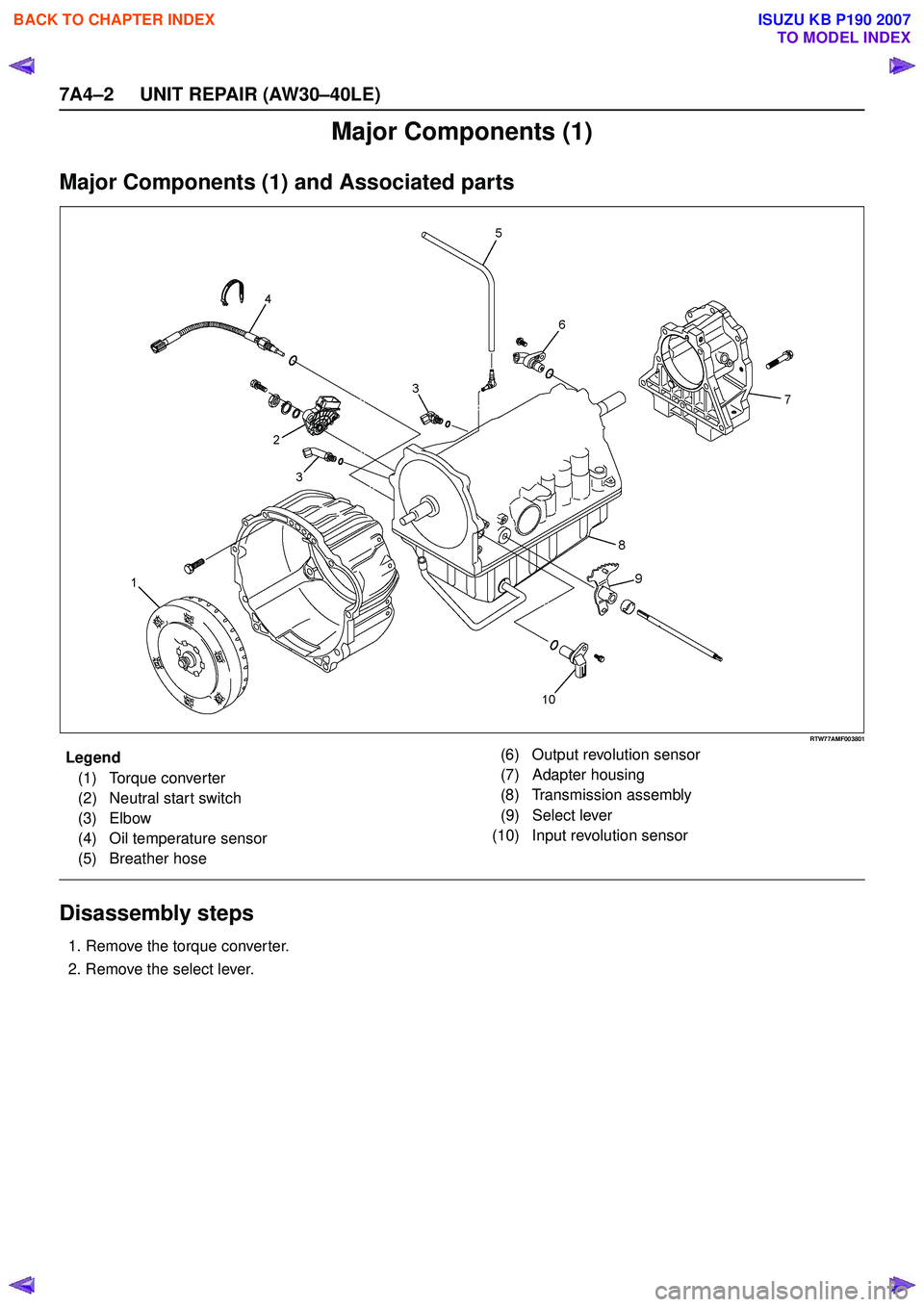
Major Components (1)
Major Components (1) and Associated parts
RTW77AMF003801
EndOFCallout
Disassembly steps
1. Remove the torque converter.
2. Remove the select lever.
Legend (1) Torque converter
(2) Neutral start switch
(3) Elbow
(4) Oil temperature sensor
(5) Breather hose (6) Output revolution sensor
(7) Adapter housing
(8) Transmission assembly
(9) Select lever
(10) Input revolution sensor
BACK TO CHAPTER INDEX
TO MODEL INDEX
ISUZU KB P190 2007
Page 4138 of 6020
UNIT REPAIR (AW30–40LE) 7A4–3
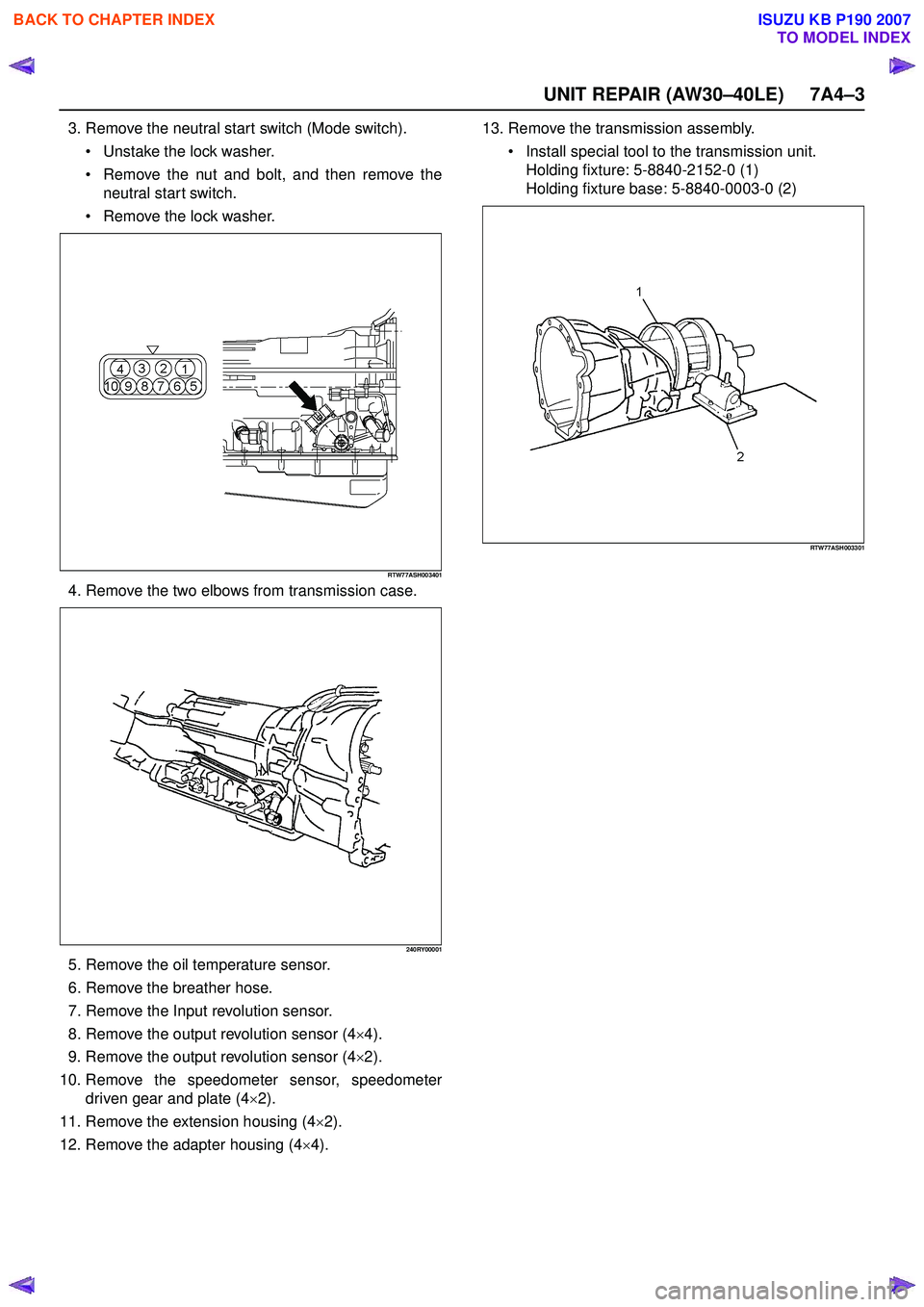
3. Remove the neutral start switch (Mode switch). Unstake the lock washer.
Remove the nut and bolt, and then remove the
neutral start switch.
Remove the lock washer.
RTW77ASH003401
4. Remove the two elbows from transmission case.
240RY00001
5. Remove the oil temperature sensor.
6. Remove the breather hose.
7. Remove the Input revolution sensor.
8. Remove the output revolution sensor (4 ×4).
9. Remove the output revolution sensor (4 ×2).
10. Remove the speedometer sensor, speedometer driven gear and plate (4 ×2).
11. Remove the extension housing (4 ×2).
12. Remove the adapter housing (4 ×4). 13. Remove the transmission assembly.
Install special tool to the transmission unit.
Holding fixture: 5-8840-2152-0 (1)
Holding fixture base: 5-8840-0003-0 (2)
RTW77ASH003301
BACK TO CHAPTER INDEX
TO MODEL INDEX
ISUZU KB P190 2007
Page 4139 of 6020
7A4–4 UNIT REPAIR (AW30–40LE)
Components (1)
Reassembly
1. Install a new gasket and the extension housing(4×2) to the transmission case.
Torque: 36 N·m (3.7 kgf·m/27 Ib ·ft)
2. Install the speedometer driven gear, plate, and speedometer sensor (4 ×2).
Torque:
Plate bolt – 15 N·m (1.5 kgf·m/11 Ib ·ft)
Speedometer sensor – 25 N·m (2.5 kgf·m/18 Ib ·ft)
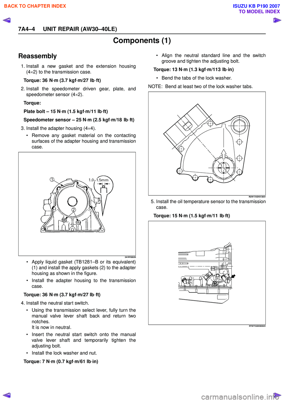
3. Install the adapter housing (4 ×4).
Remove any gasket material on the contacting
surfaces of the adapter housing and transmission
case.
241RY00020
Apply liquid gasket (TB1281 –B or its equivalent)
(1) and install the apply gaskets (2) to the adapter
housing as shown in the figure.
Install the adapter housing to the transmission
case.
Torque: 36 N·m (3.7 kgf·m/27 Ib ·ft)
4. Install the neutral start switch. Using the transmission select lever, fully turn the
manual valve lever shaft back and return two
notches.
It is now in neutral.
Insert the neutral start switch onto the manual
valve lever shaft and temporarily tighten the
adjusting bolt.
Install the lock washer and nut.
Torque: 7 N·m (0.7 kgf·m/61 Ib ·in)
Align the neutral standard line and the switch
groove and tighten the adjusting bolt.
Torque: 13 N·m (1.3 kgf·m/113 Ib ·in)
Bend the tabs of the lock washer.
NOTE: Bend at least two of the lock washer tabs.
RUW17ASH013601
5. Install the oil temperature sensor to the transmission case.
Torque: 15 N·m (1.5 kgf·m/11 Ib ·ft)
RTW77ASH003501
BACK TO CHAPTER INDEX
TO MODEL INDEX
ISUZU KB P190 2007
Page 4308 of 6020
7A2-24 TRANSMISSION CONTROL SYSTEM (JR405E)
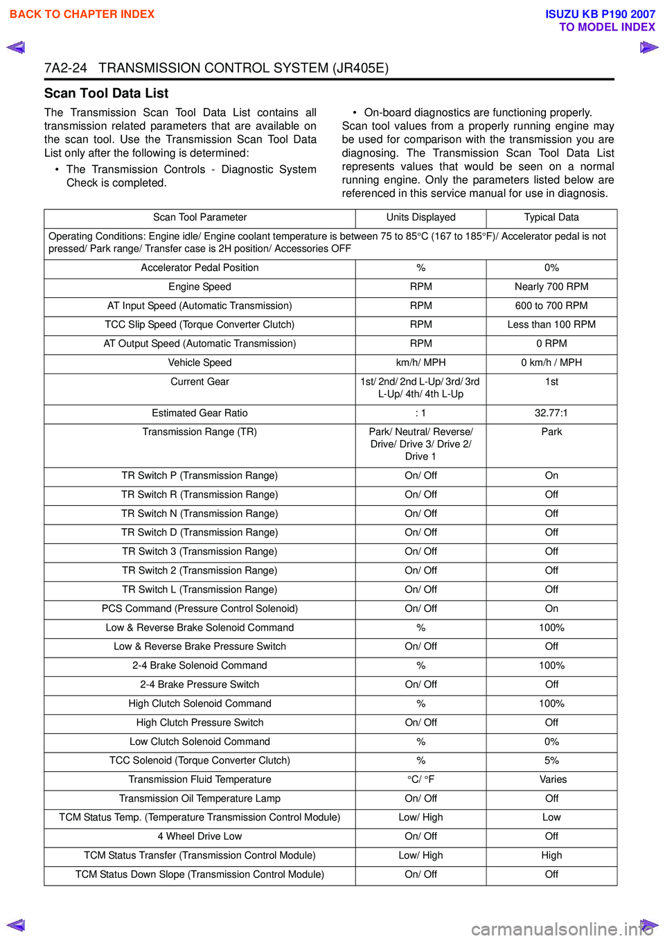
Scan Tool Data List
The Transmission Scan Tool Data List contains all
transmission related parameters that are available on
the scan tool. Use the Transmission Scan Tool Data
List only after the following is determined:
• The Transmission Controls - Diagnostic System Check is completed. • On-board diagnostics are functioning properly.
Scan tool values from a properly running engine may
be used for comparison with the transmission you are
diagnosing. The Transmission Scan Tool Data List
represents values that would be seen on a normal
running engine. Only the parameters listed below are
referenced in this service manual for use in diagnosis.
Scan Tool Parameter Units DisplayedTypical Data
Operating Conditions: Engine idle/ Engine coolant temperature is between 75 to 85 °C (167 to 185 °F)/ Accelerator pedal is not
pressed/ Park range/ Transfer case is 2H position/ Accessories OFF
Accelerator Pedal Position %0%
Engine Speed RPMNearly 700 RPM
AT Input Speed (Automatic Transmission) RPM600 to 700 RPM
TCC Slip Speed (Torque Converter Clutch) RPMLess than 100 RPM
AT Output Speed (Automatic Transmission) RPM0 RPM
Vehicle Speed km/h/ MPH0 km/h / MPH
Current Gear 1st/ 2nd/ 2nd L-Up/ 3rd/ 3rd
L-Up/ 4th/ 4th L-Up 1st
Estimated Gear Ratio : 132.77:1
Transmission Range (TR) Park/ Neutral/ Reverse/
Drive/ Drive 3/ Drive 2/ Drive 1 Park
TR Switch P (Transmission Range) On/ OffOn
TR Switch R (Transmission Range) On/ OffOff
TR Switch N (Transmission Range) On/ OffOff
TR Switch D (Transmission Range) On/ OffOff
TR Switch 3 (Transmission Range) On/ OffOff
TR Switch 2 (Transmission Range) On/ OffOff
TR Switch L (Transmission Range) On/ OffOff
PCS Command (Pressure Control Solenoid) On/ OffOn
Low & Reverse Brake Solenoid Command %100%
Low & Reverse Brake Pressure Switch On/ OffOff
2-4 Brake Solenoid Command %100%
2-4 Brake Pressure Switch On/ OffOff
High Clutch Solenoid Command %100%
High Clutch Pressure Switch On/ OffOff
Low Clutch Solenoid Command %0%
TCC Solenoid (Torque Converter Clutch) %5%
Transmission Fluid Temperature °C/ °F V arie s
Transmission Oil Temperature Lamp On/ OffOff
TCM Status Temp. (Temperature Transmission Control Module) Low/ HighLow
4 Wheel Drive Low On/ OffOff
TCM Status Transfer (Transmission Control Module) Low/ HighHigh
TCM Status Down Slope (Transmission Control Module) On/ OffOff
BACK TO CHAPTER INDEX
TO MODEL INDEX
ISUZU KB P190 2007
Page 4460 of 6020
7A3-6 ON-VEHICLE SERVICE (JR405E)
INHIBITOR SWITCH
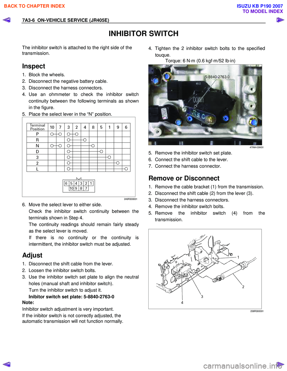
The inhibitor switch is attached to the right side of the
transmission.
Inspect
1. Block the wheels.
2. Disconnect the negative battery cable.
3. Disconnect the harness connectors.
4. Use an ohmmeter to check the inhibitor switch continuity between the following terminals as shown
in the figure.
5. Place the select lever in the “N” position.
249R300001
6. Move the select lever to either side.
Check the inhibitor switch continuity between the terminals shown in Step 4.
The continuity readings should remain fairly stead
y
as the select lever is moved.
If there is no continuity or the continuity is intermittent, the inhibitor switch must be adjusted.
Adjust
1. Disconnect the shift cable from the lever.
2. Loosen the inhibitor switch bolts.
3. Use the inhibitor switch set plate to align the neutral holes (manual shaft and inhibitor switch).
Turn the inhibitor switch to adjust it.
Inibitor switch set plate: 5-8840-2763-0
Note:
Inhibitor switch adjustment is very important.
If the inibitor switch is not correctly adjusted, the
automatic transmission will not function normally.
4. Tighten the 2 inhibitor switch bolts to the specified
touque.
Torque: 6 N·m (0.6 kgf·m/52 lb·in)
47INH-SW 01
5. Remove the inhibitor switch set plate.
6. Connect the shift cable to the lever.
7. Connect the harness connector.
Remove or Disconnect
1. Remove the cable bracket (1) from the transmission.
2. Disconnect the shift cable (2) from the lever (3).
3. Disconnect the harness connectors.
4. Remove the inhibitor switch bolts.
5. Remove the inhibitor switch (4) from the transmission.
238R300001
BACK TO CHAPTER INDEX
TO MODEL INDEX
ISUZU KB P190 2007
Page 4461 of 6020
ON-VEHICLE SERVICE (JR405E) 7A3-7
Install or Connect
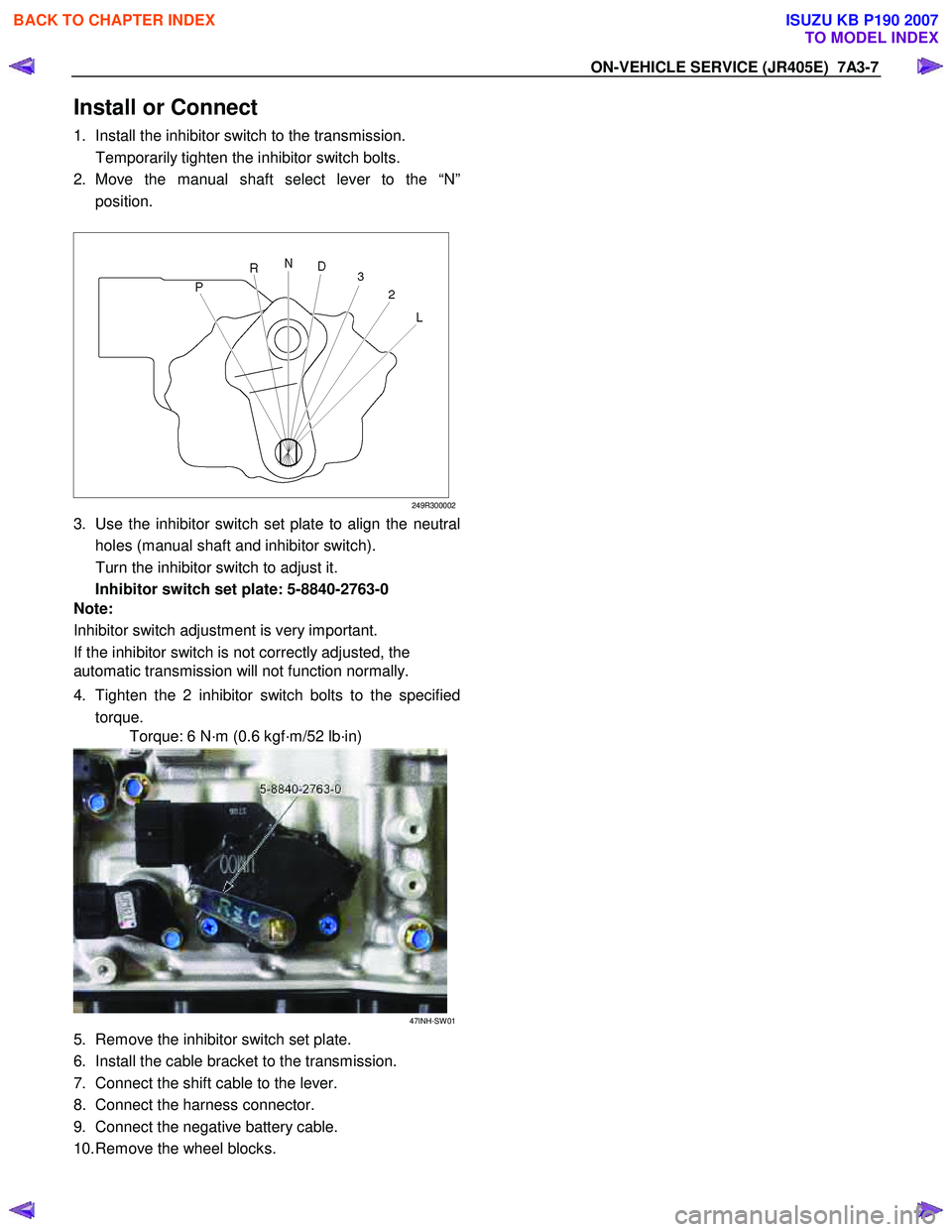
1. Install the inhibitor switch to the transmission.
Temporarily tighten the inhibitor switch bolts.
2. Move the manual shaft select lever to the “N” position.
249R300002
3. Use the inhibitor switch set plate to align the neutral
holes (manual shaft and inhibitor switch).
Turn the inhibitor switch to adjust it.
Inhibitor switch set plate: 5-8840-2763-0
Note:
Inhibitor switch adjustment is very important.
If the inhibitor switch is not correctly adjusted, the
automatic transmission will not function normally.
4. Tighten the 2 inhibitor switch bolts to the specified torque.
Torque: 6 N·m (0.6 kgf·m/52 lb·in)
47INH-SW 01
5. Remove the inhibitor switch set plate.
6. Install the cable bracket to the transmission.
7. Connect the shift cable to the lever.
8. Connect the harness connector.
9. Connect the negative battery cable.
10. Remove the wheel blocks.
BACK TO CHAPTER INDEX
TO MODEL INDEX
ISUZU KB P190 2007
Page 4473 of 6020
ON-VEHICLE SERVICE (JR405E) 7A3-19
Install or Connect
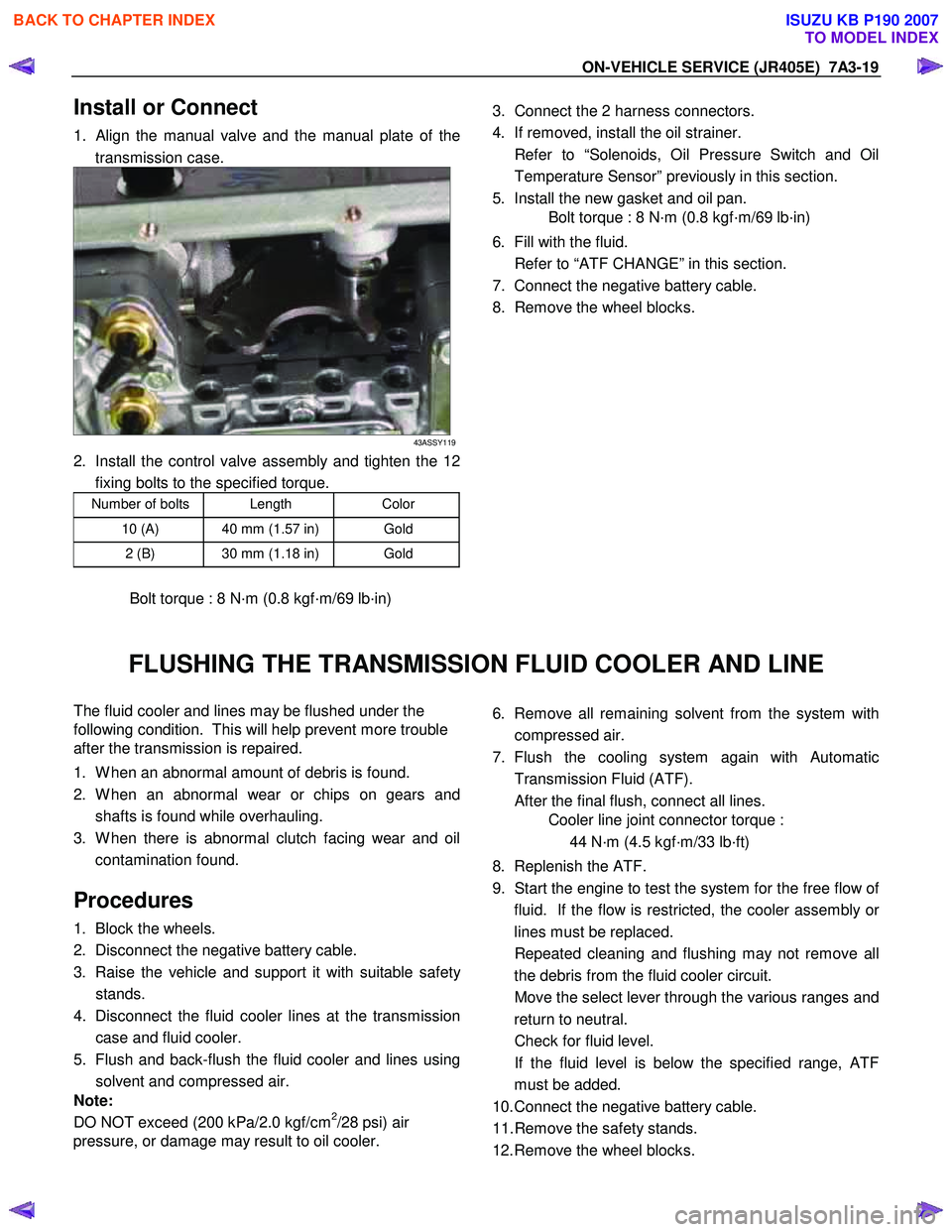
1. Align the manual valve and the manual plate of the
transmission case.
43ASSY119
2. Install the control valve assembly and tighten the 12 fixing bolts to the specified torque.
Number of bolts Length Color
10 (A) 40 mm (1.57 in) Gold
2 (B) 30 mm (1.18 in) Gold
Bolt torque : 8 N·m (0.8 kgf·m/69 lb·in)
3. Connect the 2 harness connectors.
4. If removed, install the oil strainer.
Refer to “Solenoids, Oil Pressure Switch and Oil Temperature Sensor” previously in this section.
5. Install the new gasket and oil pan.
Bolt torque : 8 N·m (0.8 kgf·m/69 lb·in)
6. Fill with the fluid.
Refer to “ATF CHANGE” in this section.
7. Connect the negative battery cable.
8. Remove the wheel blocks.
FLUSHING THE TRANSMISSION FLUID COOLER AND LINE
The fluid cooler and lines may be flushed under the
following condition. This will help prevent more trouble
after the transmission is repaired.
1. W hen an abnormal amount of debris is found.
2. W hen an abnormal wear or chips on gears and shafts is found while overhauling.
3. W hen there is abnormal clutch facing wear and oil contamination found.
Procedures
1. Block the wheels.
2. Disconnect the negative battery cable.
3. Raise the vehicle and support it with suitable safet
y
stands.
4. Disconnect the fluid cooler lines at the transmission case and fluid cooler.
5. Flush and back-flush the fluid cooler and lines using solvent and compressed air.
Note:
DO NOT exceed (200 kPa/2.0 kgf/cm
2/28 psi) air
pressure, or damage may result to oil cooler.
6. Remove all remaining solvent from the system with
compressed air.
7. Flush the cooling system again with Automatic Transmission Fluid (ATF).
After the final flush, connect all lines.
Cooler line joint connector torque :
44 N·m (4.5 kgf·m/33 lb·ft)
8. Replenish the ATF.
9. Start the engine to test the system for the free flow o
f
fluid. If the flow is restricted, the cooler assembly o
r
lines must be replaced.
Repeated cleaning and flushing may not remove all the debris from the fluid cooler circuit.
Move the select lever through the various ranges and return to neutral.
Check for fluid level.
If the fluid level is below the specified range, ATF must be added.
10. Connect the negative battery cable.
11. Remove the safety stands.
12. Remove the wheel blocks.
BACK TO CHAPTER INDEX
TO MODEL INDEX
ISUZU KB P190 2007