2007 ISUZU KB P190 Neutral switch
[x] Cancel search: Neutral switchPage 4891 of 6020
TRANSFER CONTROL SYSTEM 7D1-17
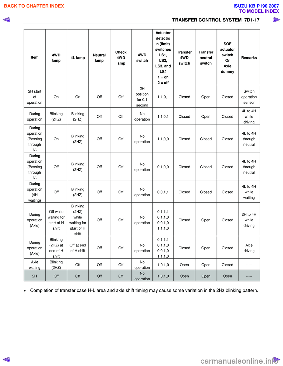
Item 4WD
lamp 4L lamp Neutral
lamp Check
4WD
lamp 4WD
switch Actu ato r
detection (limit)
switches LS1,
LS2,
LS3. and LS4
1 = on
2 = off Transfer
4WD
switch Transfer
neutral switch SOF
actuator switch Or
Axl e
dummy Remarks
2H start
of
operation On On Off Off 2H
position for 0.1
second 1,1,0,1 Closed Open Closed
Switch
operation sensor
During
operation Blinking
(2HZ) Blinking
(2HZ) Off Off No
operation 1,1,0,1 Closed Open Closed 4L to 4H
while
driving
During
operation (Passing through N) On
Blinking
(2HZ) Off Off No
operation 1,1,0,0 Closed Closed Closed 4L to 4H
through neutral
During
operation (Passing through N) Off
Blinking
(2HZ) Off Off No
operation 0,1,0,0 Closed Closed Closed 4L to 4H
through neutral
During
operation (4H
waiting) Off
Blinking
(2HZ) Off Off No
operation 0,0,1,1 Closed Closed Closed 4L to 4H
while
waiting
During
operation (Axle) Off while
waiting for start of H shift Blinking
(2HZ) while
waiting for start of H shift Off Off
No
operation 0,1,1,1
0,1,1,0
0,0,1,0
1,1,1,0 Closed Open Closed
2H to 4H
while
driving
During
operation (Axle) Blinking
(2HZ) at
end of H shift Off at end
of H shift Off Off No
operation 0,1,1,1
0,1,1,0
0,0,1,0
1,1,1,0 Closed Open Closed
Axle
driving
Axle
waiting
Blinking
(2HZ) Off Off Off No
operation1,0,1,0 Open Open Closed -----
2H Off Off Off Off No
operation1,0,1,0 Open Open Open -----
• Completion of transfer case H-L area and axle shift timing may cause some variation in the 2Hz blinking pattern.
BACK TO CHAPTER INDEX
TO MODEL INDEX
ISUZU KB P190 2007
Page 4893 of 6020
TRANSFER CONTROL SYSTEM 7D1-19
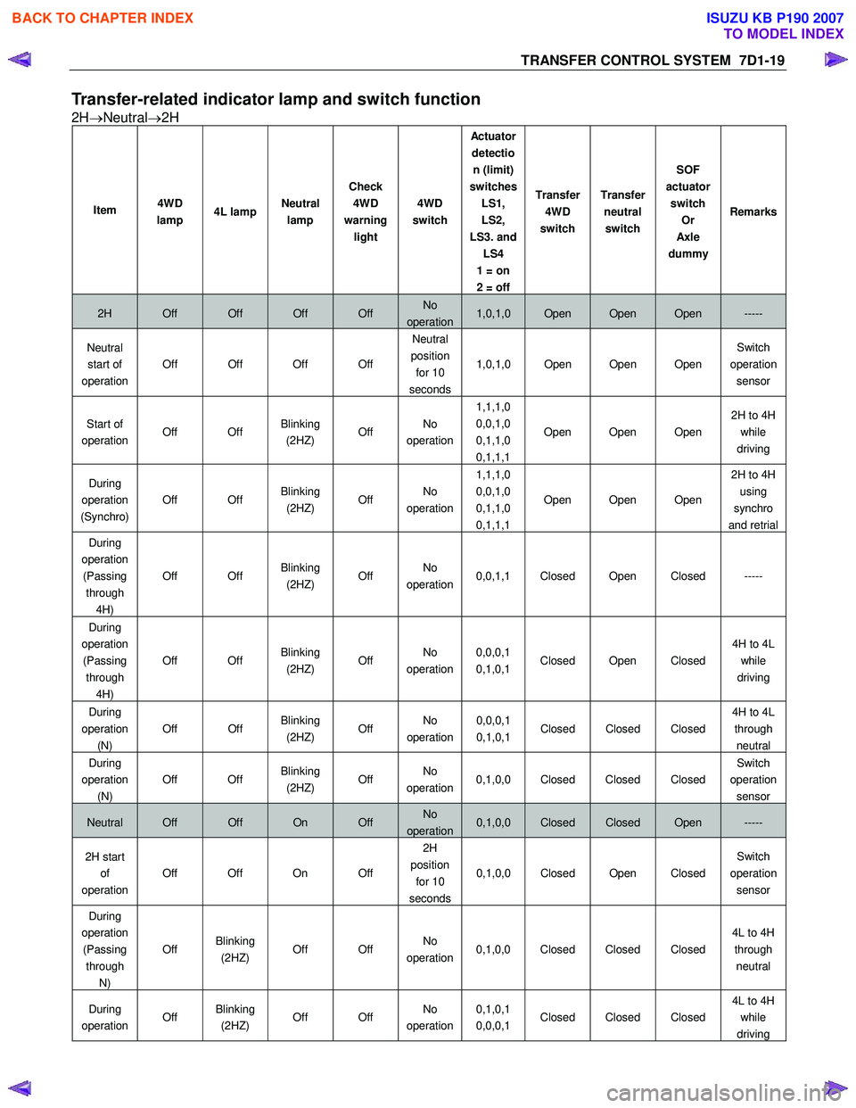
Transfer-related indicator lamp and switch function
2H→Neutral →2H
Item 4WD
lamp 4L lamp Neutral
lamp Check
4WD
warning light 4WD
switch Actu ato r
detection (limit)
switches LS1,
LS2,
LS3. and LS4
1 = on
2 = off Transfer
4WD
switch Transfer
neutral switch SOF
actuator switch Or
Axl e
dummy Remarks
2H Off Off Off Off No
operation1,0,1,0 Open Open Open -----
Neutral
start of
operation Off Off Off Off Neutral
position for 10
seconds 1,0,1,0 Open Open Open
Switch
operation sensor
Start of
operation Off Off Blinking
(2HZ) Off No
operation 1,1,1,0
0,0,1,0
0,1,1,0
0,1,1,1 Open Open Open
2H to 4H
while
driving
During
operation
(Synchro) Off Off
Blinking
(2HZ) Off No
operation 1,1,1,0
0,0,1,0
0,1,1,0
0,1,1,1 Open Open Open 2H to 4H
using
synchro
and retrial
During
operation (Passing through 4H) Off Off
Blinking
(2HZ) Off No
operation 0,0,1,1 Closed Open Closed -----
During
operation (Passing through 4H) Off Off
Blinking
(2HZ) Off No
operation 0,0,0,1
0,1,0,1 Closed Open Closed 4H to 4L
while
driving
During
operation
(N)
Off Off Blinking
(2HZ) Off No
operation
0,0,0,1
0,1,0,1 Closed Closed Closed
4H to 4L
through
neutral
During
operation (N) Off Off
Blinking
(2HZ) Off No
operation 0,1,0,0 Closed Closed Closed Switch
operation sensor
Neutral Off Off On Off No
operation0,1,0,0 Closed Closed Open -----
2H start of
operation Off Off On Off 2H
position for 10
seconds 0,1,0,0 Closed Open Closed
Switch
operation sensor
During
operation (Passing through N) Off
Blinking
(2HZ) Off Off No
operation 0,1,0,0 Closed Closed Closed 4L to 4H
through neutral
During
operation Off Blinking
(2HZ) Off Off No
operation 0,1,0,1
0,0,0,1 Closed Closed Closed 4L to 4H
while
driving
BACK TO CHAPTER INDEX
TO MODEL INDEX
ISUZU KB P190 2007
Page 4894 of 6020
7D1-20 TRANSFER CONTROL SYSTEM
Item 4WD
lamp 4L lamp Neutral
lamp Check
4WD
warning light 4WD
switch Actu ato r
detection (limit)
switches LS1,
LS2,
LS3. and LS4
1 = on
2 = off Transfer
4WD
switch Transfer
neutral switch SOF
actuator switch Or
Axl e
dummy Remarks
During
operation (4H
waiting) Off
Blinking
(2HZ) Off Off No
operation 0,0,1,1 Closed Closed Closed 4L to 4H
while
waiting
During
operation (Axle) Blinking
(2HZ) Off Off Off No
operation 0,1,1,1
0,1,1,0
0,0,1,0
1,1,1,0 Closed Open Closed
2H to 4H
while
driving
During
operation (Axle) Blinking
(2HZ) Off Off Off No
operation 0,1,1,1
0,1,1,0
0,0,1,0
1,1,1,0 Open Open Closed
Axle
driving
Axle
waiting
Blinking
(2HZ) Off Off Off No
operation1,0,1,0 Open Open Closed -----
2H Off Off Off Off No
operation1,0,1,0 Open Open Open -----
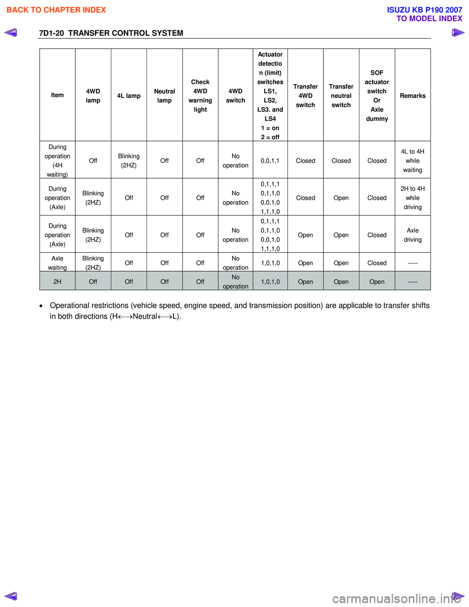
• Operational restrictions (vehicle speed, engine speed, and transmission position) are applicable to transfer shifts
in both directions (H ←→Neutral ←→L).
BACK TO CHAPTER INDEX
TO MODEL INDEX
ISUZU KB P190 2007
Page 4916 of 6020
7D1-42 TRANSFER CONTROL SYSTEM
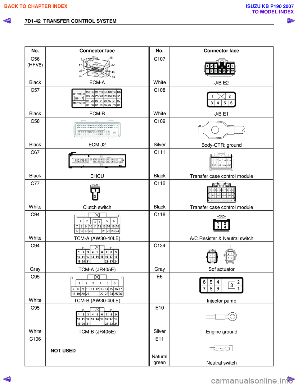
No. Connector face No. Connector face
C56
(HFV6)
Black
ECM-A C107
WhiteJ/B E2
C57
Black ECM-B C108
WhiteJ/B E1
C58
Black ECM J2 C109
SilverBody-CTR; ground
C67
Black
EHCU C111
BlackTransfer case control module
C77
White
Clutch switch C112
BlackTransfer case control module
C94
White
TCM-A (AW 30-40LE) C118
A/C Resister & Neutral switch
C94
Gray
TCM-A (JR405E) C134
Gray Sof actuator
C95
White
TCM-B (AW 30-40LE) E6
Injector pump
C95
White
TCM-B (JR405E) E10
SilverEngine ground
C106
NOT USED E11
Natural green
Neutral switch
BACK TO CHAPTER INDEX
TO MODEL INDEX
ISUZU KB P190 2007
Page 4917 of 6020
TRANSFER CONTROL SYSTEM 7D1-43
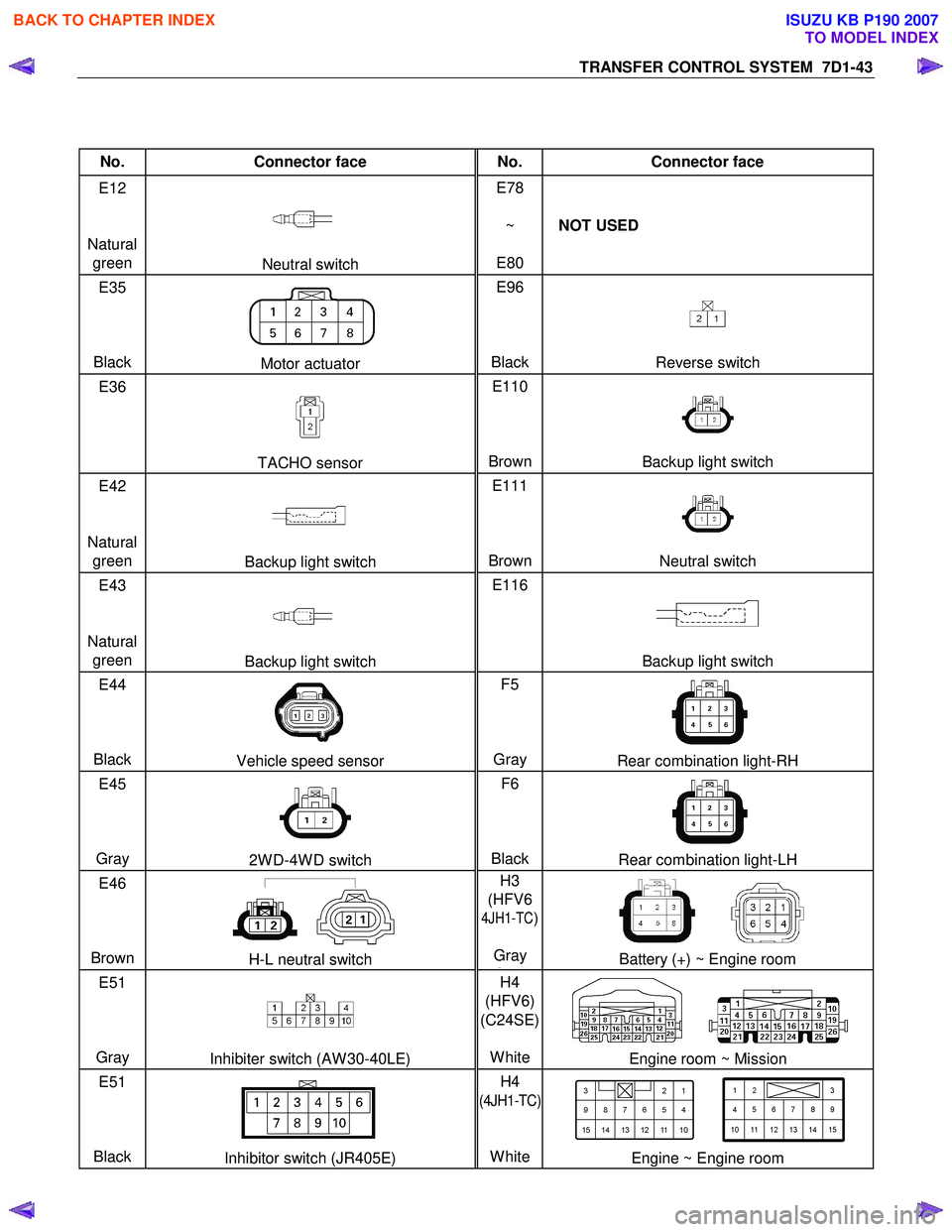
No. Connector face No. Connector face
E12
Natural green
Neutral switch E78
~
E80 NOT USED
E35
Black
Motor actuator E96
BlackReverse switch
E36
TACHO sensor E110
BrownBackup light switch
E42
Natural green
Backup light switch E111
BrownNeutral switch
E43
Natural green
Backup light switch E116
Backup light switch
E44
Black
Vehicle speed sensor F5
Gray Rear combination light-RH
E45
Gray
2W D-4W D switch F6
BlackRear combination light-LH
E46
Brown
H-L neutral switch H3
(HFV6
4JH1-TC)
Gray
GBattery (+) ~ Engine room
E51
Gray
Inhibiter switch (AW 30-40LE) H4
(HFV6)
(C24SE)
WhiteEngine room ~ Mission
E51
Black
Inhibitor switch (JR405E) H4
(4JH1-TC)
White
Engine ~ Engine room
BACK TO CHAPTER INDEX
TO MODEL INDEX
ISUZU KB P190 2007
Page 4918 of 6020
7D1-44 TRANSFER CONTROL SYSTEM
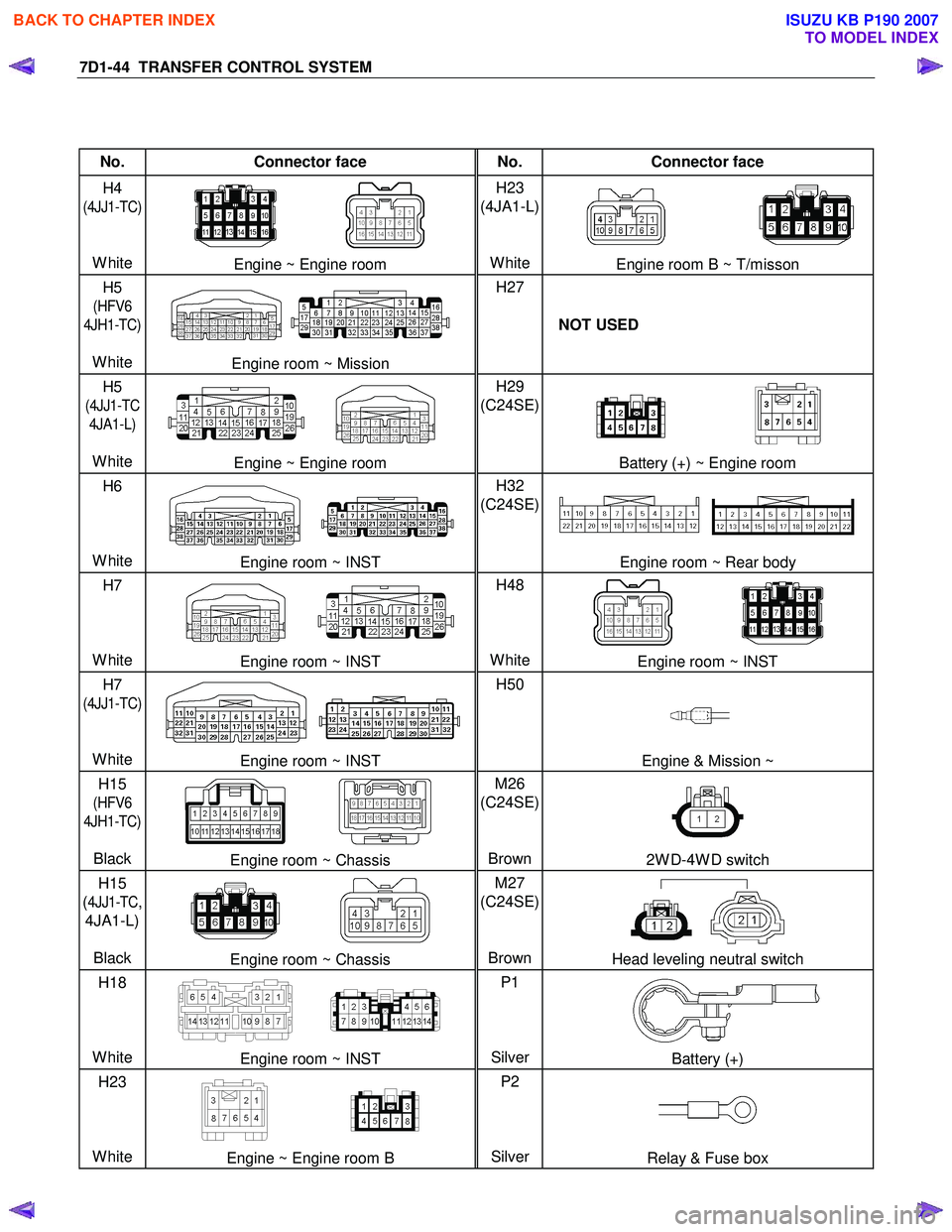
No. Connector face No. Connector face
H4
(4JJ1-TC)
White
Engine ~ Engine room H23
(4JA1-L)
WhiteEngine room B ~ T/misson
H5
(HFV6
4JH1-TC)
White
Engine room ~ Mission H27
NOT USED
H5
(4JJ1-TC
4JA1-L)
White
Engine ~ Engine room H29
(C24SE)
Battery (+) ~ Engine room
H6
White
Engine room ~ INST H32
(C24SE)
Engine room ~ Rear body
H7
White
Engine room ~ INST H48
WhiteEngine room ~ INST
H7
(4JJ1-TC)
White
Engine room ~ INST H50
Engine & Mission ~
H15
(HFV6
4JH1-TC)
Black
Engine room ~ Chassis M26
(C24SE)
Brown2W D-4W D switch
H15
(
4JJ1-TC,
4JA1-L)
Black
Engine room ~ Chassis M27
(C24SE)
BrownHead leveling neutral switch
H18
White
Engine room ~ INST P1
SilverBattery (+)
H23
White
Engine ~ Engine room B P2
SilverRelay & Fuse box
BACK TO CHAPTER INDEX
TO MODEL INDEX
ISUZU KB P190 2007
Page 4921 of 6020
TRANSFER CONTROL SYSTEM 7D1-47
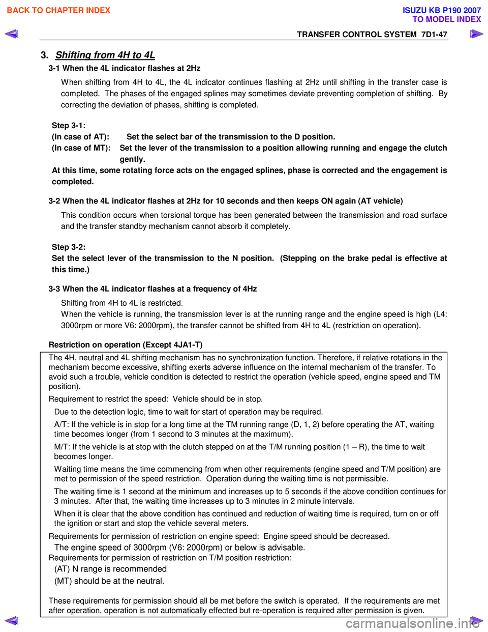
3. Shifting from 4H to 4L
3-1 When the 4L indicator flashes at 2Hz
W hen shifting from 4H to 4L, the 4L indicator continues flashing at 2Hz until shifting in the transfer case is
completed. The phases of the engaged splines may sometimes deviate preventing completion of shifting. By
correcting the deviation of phases, shifting is completed.
Step 3-1:
(In case of AT): Set the select bar of the transmission to the D position.
(In case of MT): Set the lever of the transmission to a position allowing running and engage the clutch gently.
At this time, some rotating force acts on the engaged splines, phase is corrected and the engagement is
completed.
3-2 When the 4L indicator flashes at 2Hz for 10 seconds and then keeps ON again (AT vehicle)
This condition occurs when torsional torque has been generated between the transmission and road surface
and the transfer standby mechanism cannot absorb it completely.
Step 3-2:
Set the select lever of the transmission to the N position. (Stepping on the brake pedal is effective at
this time.)
3-3 When the 4L indicator flashes at a frequency of 4Hz
Shifting from 4H to 4L is restricted.
W hen the vehicle is running, the transmission lever is at the running range and the engine speed is high (L4:
3000rpm or more V6: 2000rpm), the transfer cannot be shifted from 4H to 4L (restriction on operation).
Restriction on operation (Except 4JA1-T)
The 4H, neutral and 4L shifting mechanism has no synchronization function. Therefore, if relative rotations in the
mechanism become excessive, shifting exerts adverse influence on the internal mechanism of the transfer. To
avoid such a trouble, vehicle condition is detected to restrict the operation (vehicle speed, engine speed and TM
position).
Requirement to restrict the speed: Vehicle should be in stop. Due to the detection logic, time to wait for start of operation may be required.
A/T: If the vehicle is in stop for a long time at the TM running range (D, 1, 2) before operating the AT, waiting
time becomes longer (from 1 second to 3 minutes at the maximum).
M/T: If the vehicle is at stop with the clutch stepped on at the T/M running position (1 – R), the time to wait
becomes longer.
W aiting time means the time commencing from when other requirements (engine speed and T/M position) are
met to permission of the speed restriction. Operation during the waiting time is not permissible.
The waiting time is 1 second at the minimum and increases up to 5 seconds if the above condition continues for
3 minutes. After that, the waiting time increases up to 3 minutes in 2 minute intervals.
W hen it is clear that the above condition has continued and reduction of waiting time is required, turn on or off
the ignition or start and stop the vehicle several meters.
Requirements for permission of restriction on engine speed: Engine speed should be decreased.
The engine speed of 3000rpm (V6: 2000rpm) or below is advisable.
Requirements for permission of restriction on T/M position restriction:
(AT) N range is recommended
(MT) should be at the neutral.
These requirements for permission should all be met before the switch is operated. If the requirements are met
after operation, operation is not automatically effected but re-operation is required after permission is given.
BACK TO CHAPTER INDEX
TO MODEL INDEX
ISUZU KB P190 2007
Page 4922 of 6020
7D1-48 TRANSFER CONTROL SYSTEM
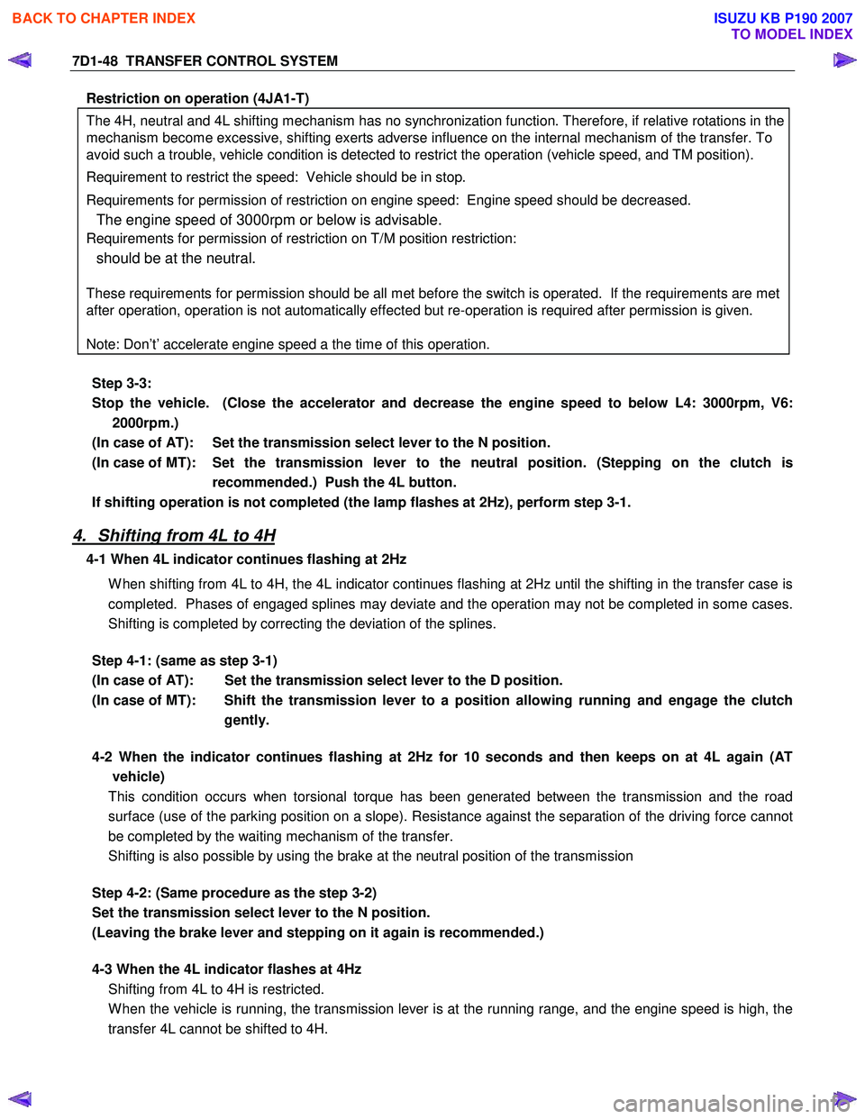
Restriction on operation (4JA1-T)
The 4H, neutral and 4L shifting mechanism has no synchronization function. Therefore, if relative rotations in the
mechanism become excessive, shifting exerts adverse influence on the internal mechanism of the transfer. To
avoid such a trouble, vehicle condition is detected to restrict the operation (vehicle speed, and TM position).
Requirement to restrict the speed: Vehicle should be in stop.
Requirements for permission of restriction on engine speed: Engine speed should be decreased.
The engine speed of 3000rpm or below is advisable.
Requirements for permission of restriction on T/M position restriction:
should be at the neutral.
These requirements for permission should be all met before the switch is operated. If the requirements are met
after operation, operation is not automatically effected but re-operation is required after permission is given.
Note: Don’t’ accelerate engine speed a the time of this operation.
Step 3-3:
Stop the vehicle. (Close the accelerator and decrease the engine speed to below L4: 3000rpm, V6: 2000rpm.)
(In case of AT): Set the transmission select lever to the N position.
(In case of MT): Set the transmission lever to the neutral position. (Stepping on the clutch is recommended.) Push the 4L button.
If shifting operation is not completed (the lamp flashes at 2Hz), perform step 3-1.
4. Shifting from 4L to 4H
4-1 When 4L indicator continues flashing at 2Hz
W hen shifting from 4L to 4H, the 4L indicator continues flashing at 2Hz until the shifting in the transfer case is
completed. Phases of engaged splines may deviate and the operation may not be completed in some cases.
Shifting is completed by correcting the deviation of the splines.
Step 4-1: (same as step 3-1)
(In case of AT): Set the transmission select lever to the D position.
(In case of MT): Shift the transmission lever to a position allowing running and engage the clutch gently.
4-2 When the indicator continues flashing at 2Hz for 10 seconds and then keeps on at 4L again (AT
vehicle)
This condition occurs when torsional torque has been generated between the transmission and the road
surface (use of the parking position on a slope). Resistance against the separation of the driving force cannot
be completed by the waiting mechanism of the transfer.
Shifting is also possible by using the brake at the neutral position of the transmission
Step 4-2: (Same procedure as the step 3-2)
Set the transmission select lever to the N position.
(Leaving the brake lever and stepping on it again is recommended.)
4-3 When the 4L indicator flashes at 4Hz
Shifting from 4L to 4H is restricted.
W hen the vehicle is running, the transmission lever is at the running range, and the engine speed is high, the
transfer 4L cannot be shifted to 4H.
BACK TO CHAPTER INDEX
TO MODEL INDEX
ISUZU KB P190 2007