Page 4733 of 6020
7B1-14 Manual Transmission (MUX)
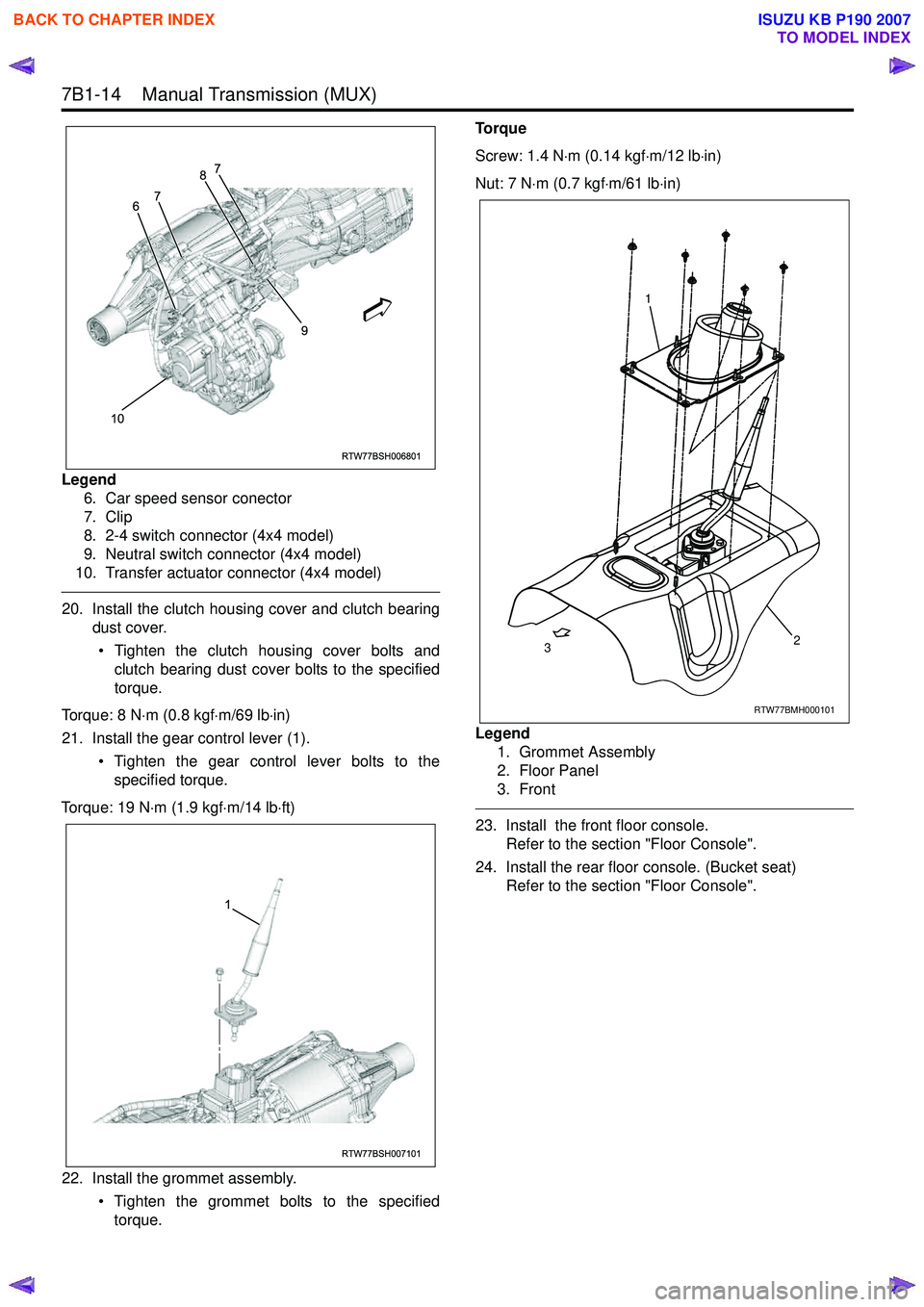
Legend6. Car speed sensor conector
7. Clip
8. 2-4 switch connector (4x4 model)
9. Neutral switch connector (4x4 model)
10. Transfer actuator connector (4x4 model)
20. Install the clutch housing cover and clutch bearing dust cover.
• Tighten the clutch housing cover bolts and clutch bearing dust cover bolts to the specified
torque.
Torque: 8 N ⋅m (0.8 kgf ⋅m/69 lb ⋅in)
21. Install the gear control lever (1). • Tighten the gear control lever bolts to thespecified torque.
Torque: 19 N ⋅m (1.9 kgf ⋅m/14 lb ⋅ft)
22. Install the grommet assembly. • Tighten the grommet bolts to the specifiedtorque. Torque
Screw: 1.4 N ⋅m (0.14 kgf ⋅m/12 lb ⋅in)
Nut: 7 N ⋅m (0.7 kgf ⋅m/61 lb ⋅in)
Legend 1. Grommet Assembly
2. Floor Panel
3. Front
23. Install the front floor console. Refer to the section "Floor Console".
24. Install the rear floor console. (Bucket seat) Refer to the section "Floor Console".
RTW77BSH006801
10 9
6
7 8
7
RTW77BSH007101
1
RTW77BMH000101
1
2
3
BACK TO CHAPTER INDEX
TO MODEL INDEX
ISUZU KB P190 2007
Page 4735 of 6020
7B1-16 Manual Transmission (MUX)
Transmission
Component
Legend1. Front case assembly with clutch housing
2. Front cover
3. Reverse switch
4. 1st switch
5. Reverse detent assembly
6. Neutral switch
7. Intermediate plate assembly
8. 5th detent assembly
9. Filler plug
10. Drain plug 11. Rear case assembly
12. End cover assembly (4x4 model) 13. Output shaft snap ring
14. Output rear bearing inner race
15. Speedometer driven gear
16. End cover assembly (4x2 model)
17. End cover gasket
18. Gear set clip
19. Speedometer drive gear
20. Straight plug
21. Dowel
22. Control rod detent assembly
23. Quadrant box
RTW77BLF001901
16
1718191314
1
23
22
20
12
13
14
2
3
4
5
6
21
21
11
10
9
8
7
15
BACK TO CHAPTER INDEX
TO MODEL INDEX
ISUZU KB P190 2007
Page 4738 of 6020
Manual Transmission (MUX) 7B1-19
b. Remove the taper bolt, and discard the usedtaper bolt.
c. Remove the control unit block.
7. Remove the reverse switch (Connector color Brown), 1st switch (Connector color Gray) and
neutral switch (Connector color Brown) with
gasket.
Remove the three detent assemblies, and discard
the used 5th & reverse detent assemblies.
8. Remove the two harness brackets.
9. Remove the speedometer driven gear and plate. (4x2 model)
10. Remove the end cover assembly. 11. Remove the gear set clip. (4x2 model)
12. Remove the speedometer drive gear. (4x2 model)
13. Stand the transmission assembly.
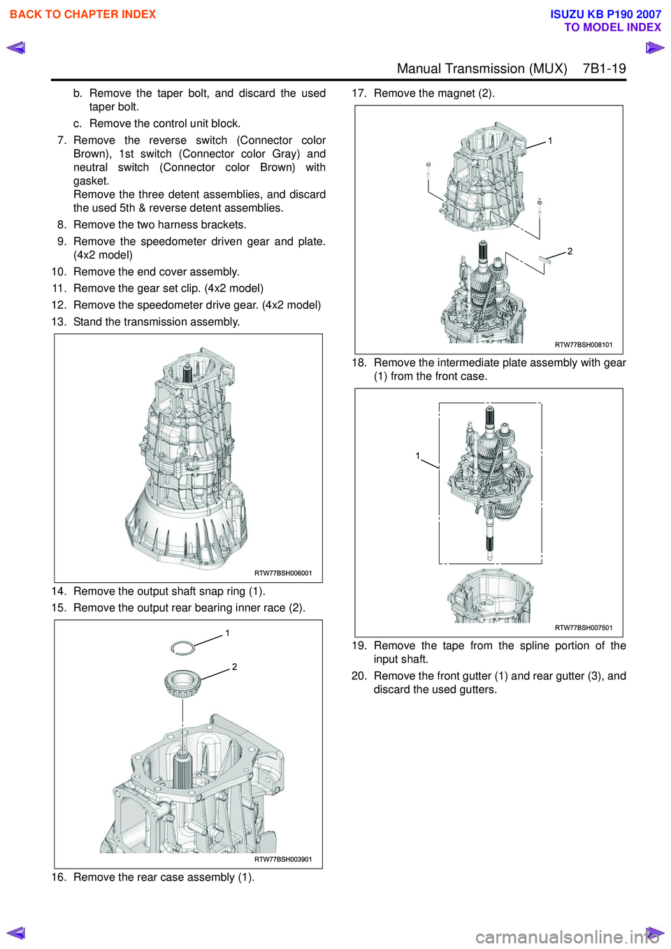
14. Remove the output shaft snap ring (1).
15. Remove the output rear bearing inner race (2).
16. Remove the rear case assembly (1). 17. Remove the magnet (2).
18. Remove the intermediate plate assembly with gear (1) from the front case.
19. Remove the tape from the spline portion of the input shaft.
20. Remove the front gutter (1) and rear gutter (3), and discard the used gutters.
RTW77BSH006001
RTW77BSH003901
2
1
RTW77BSH008101
1
2
RTW77BSH007501
1
BACK TO CHAPTER INDEX
TO MODEL INDEX
ISUZU KB P190 2007
Page 4751 of 6020
7B1-32 Manual Transmission (MUX)
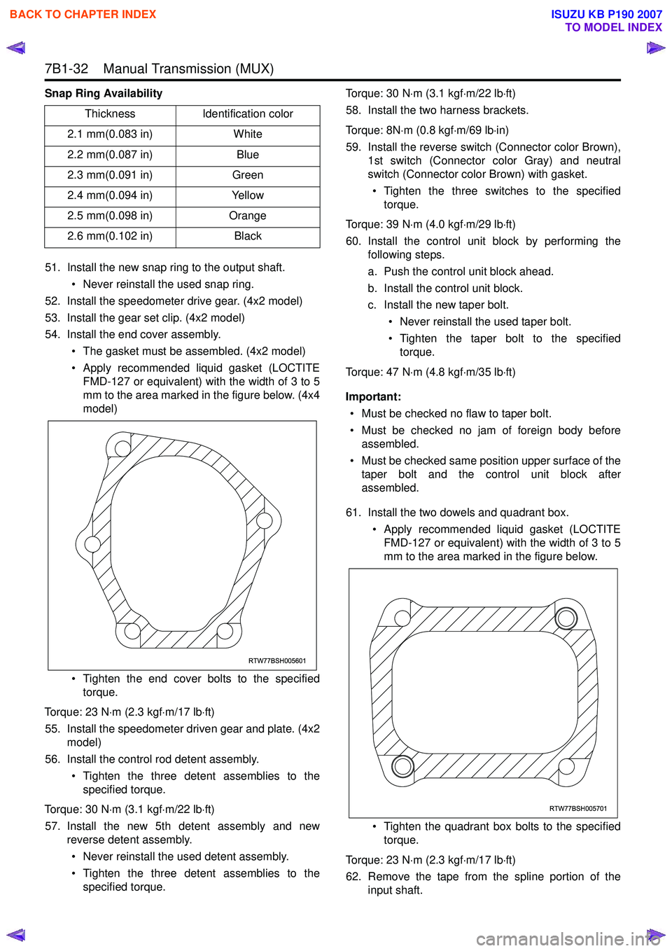
Snap Ring Availability51. Install the new snap ring to the output shaft. • Never reinstall the used snap ring.
52. Install the speedometer drive gear. (4x2 model)
53. Install the gear set clip. (4x2 model)
54. Install the end cover assembly.
• The gasket must be assembled. (4x2 model)
• Apply recommended liquid gasket (LOCTITE FMD-127 or equivalent) with the width of 3 to 5
mm to the area marked in the figure below. (4x4
model)
• Tighten the end cover bolts to the specified torque.
Torque: 23 N ⋅m (2.3 kgf ⋅m/17 lb ⋅ft)
55. Install the speedometer driven gear and plate. (4x2 model)
56. Install the control rod detent assembly.
• Tighten the three detent assemblies to thespecified torque.
Torque: 30 N ⋅m (3.1 kgf ⋅m/22 lb ⋅ft)
57. Install the new 5th detent assembly and new reverse detent assembly.
• Never reinstall the used detent assembly.
• Tighten the three detent assemblies to the specified torque. Torque: 30 N
⋅m (3.1 kgf ⋅m/22 lb ⋅ft)
58. Install the two harness brackets.
Torque: 8N ⋅m (0.8 kgf ⋅m/69 lb ⋅in)
59. Install the reverse switch (Connector color Brown), 1st switch (Connector color Gray) and neutral
switch (Connector color Brown) with gasket.
• Tighten the three switches to the specified torque.
Torque: 39 N ⋅m (4.0 kgf ⋅m/29 lb ⋅ft)
60. Install the control unit block by performing the following steps.
a. Push the control unit block ahead.
b. Install the control unit block.
c. Install the new taper bolt.
• Never reinstall the used taper bolt.
• Tighten the taper bolt to the specified torque.
Torque: 47 N ⋅m (4.8 kgf ⋅m/35 lb ⋅ft)
Important: • Must be checked no flaw to taper bolt.
• Must be checked no jam of foreign body before assembled.
• Must be checked same position upper surface of the taper bolt and the control unit block after
assembled.
61. Install the two dowels and quadrant box. • Apply recommended liquid gasket (LOCTITEFMD-127 or equivalent) with the width of 3 to 5
mm to the area marked in the figure below.
• Tighten the quadrant box bolts to the specified torque.
Torque: 23 N ⋅m (2.3 kgf ⋅m/17 lb ⋅ft)
62. Remove the tape from the spline portion of the input shaft.
Thickness
Identification color
2.1 mm(0.083 in) White
2.2 mm(0.087 in) Blue
2.3 mm(0.091 in) Green
2.4 mm(0.094 in) Yellow
2.5 mm(0.098 in) Orange
2.6 mm(0.102 in) Black
RTW77BSH005601
RTW77BSH005701
BACK TO CHAPTER INDEX
TO MODEL INDEX
ISUZU KB P190 2007
Page 4848 of 6020
7D-18 TRANSFER CASE
Transfer Disassembly
RTW 67DLF000101
Legend
(1) Transfer Case Speedometer Bushing, Plate and Driven Gear
(2) Companion Flange, O-ring and Nut
(8)
(M/T: MUA, MUX, A/T: JR405E, AW 30-40LE)
(3) Stoneguard (9) Speed sensor (M/T: AR-5, A/T: 4L60-E)
(4) Detent Plug, Spring and Detent Ball (10) Transfer Actuator (Diesel Engine)
(5) 2-4 Switch ASM (11) Transfer Actuator (Gasoline Engine)
(6) Switch Bracket (12) Breather Hose
(7) Neutral Switch ASM (13) Heat Protector (Gasoline Engine)
Removal
1. Remove the stoneguard.
2. Remove the drain plug from the transfer case to drain
the oil.
3. Remove the parts listed below.
• Speedometer bushing, plate, and speedomete
r
driven gear (M/T: MUA, MUX, A/T: JR405E,
AW 30-40LE)
• Speed sensor (M/T: AR-5, A/T: 4L60-E)
BACK TO CHAPTER INDEX
TO MODEL INDEX
ISUZU KB P190 2007
Page 4849 of 6020
TRANSFER CASE 7D-19
• Breather hose (Between the transfer case and the
transfer actuator assembly)
• Transfer actuator assembly
• Switch bracket
• 2-4 switch assembly (Gray harness cover)
• Neutral switch assembly (Black harness cover)
• Detent plugs, detent springs, and detent balls (2
parts each)
4. Use a flange holder (5-8840-0133-0) to remove the
end nut from the front companion flange.
RTW 77DSH000201
5. Remove the bolts attaching the rear cover to the
transfer case.
6. Strike the area around the front output shaft head and
the rear cover bolt holes with a plastic hammer to
remove the rear cover.
220R300022
BACK TO CHAPTER INDEX
TO MODEL INDEX
ISUZU KB P190 2007
Page 4857 of 6020
TRANSFER CASE 7D-27
Inspection and Repair
1. Make the necessary repair or parts replacement if
wear, damage or any other abnormal conditions are
found during inspection.
2. W ash all parts thoroughly in clean solvent. Be sure all
old lubricant, metallic particles, dirt, or foreign material
are removed from the surfaces of every part. Appl
y
compressed air to each oil feed port and channel in
each case half to remove any obstructions or cleaning
solvent residue.
Inspection and Repair (Transfer Case
Assembly)
W hen wear, damage, or any other defects are observed
during the inspection, the part or parts must be repaired
or replaced. W ash all the parts with clean detergent, and
check that old oil, metallic particles, dirt, or foreign
materials are completely removed. Blow the air into oil
holes and grooves to remove foreign materials or
residual detergent.
Chain
• Check whether the face that contacts the sprocket is
free from excessive wear or damage. If defects are
observed, replace the part.
• If the chain interference mark is found on the inside
wall of the transfer cover or the chain is so slack that a
skipped engagement occurs between the chain and
sprocket, replace the chain.
Sprocket
• Check whether the sprocket tooth surface is
excessively worn or damaged, and there is evidence
of burrs, chipping, wear, or damage on the gear
spline. Remove minor flaws or scratches with oil
stone. If excessive wear or damage is observed,
replace the part.
• If excessive wear or damage is observed on the
sprocket inside sliding surface, replace the part.
Gear
• Check whether the gear tooth surface is excessively
worn or damaged, and there is evidence of burrs,
chipping, wear, or damage on the gear spline.
• Remove minor flaws or scratches with oil stone. I
f
excessive wear or damage is observed, replace the
part.
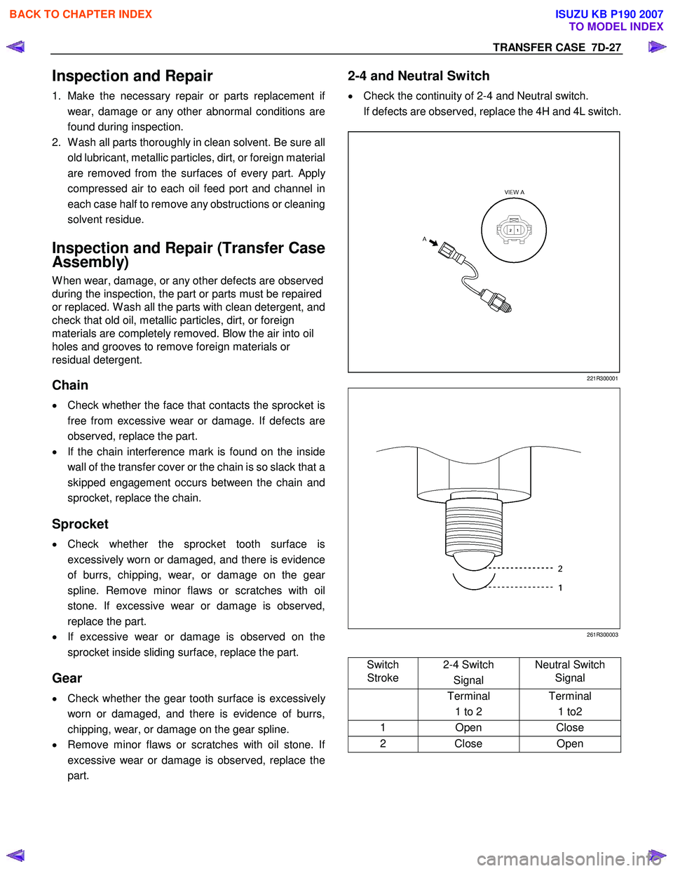
2-4 and Neutral Switch
• Check the continuity of 2-4 and Neutral switch.
If defects are observed, replace the 4H and 4L switch.
221R300001
261R300003
Switch
Stroke 2-4 Switch
Signal Neutral Switch
Signal
Terminal
1 to 2 Terminal
1 to2
1 Open Close
2 Close Open
BACK TO CHAPTER INDEX
TO MODEL INDEX
ISUZU KB P190 2007
Page 4869 of 6020
TRANSFER CASE 7D-39
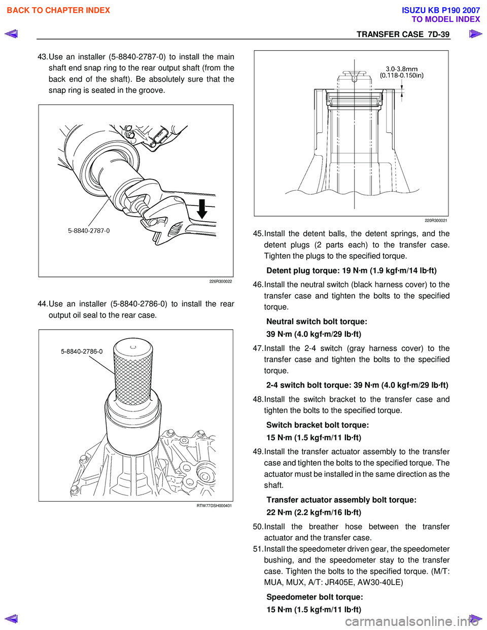
43. Use an installer (5-8840-2787-0) to install the main
shaft end snap ring to the rear output shaft (from the
back end of the shaft). Be absolutely sure that the
snap ring is seated in the groove.
226R300022
44. Use an installer (5-8840-2786-0) to install the rear
output oil seal to the rear case.
RTW 77DSH000401
220R300021
45.
Install the detent balls, the detent springs, and the
detent plugs (2 parts each) to the transfer case.
Tighten the plugs to the specified torque.
Detent plug torque: 19 N ·m (1.9 kgf ·m/14 lb ·ft)
46. Install the neutral switch (black harness cover) to the
transfer case and tighten the bolts to the specified
torque.
Neutral switch bolt torque:
39 N ·m (4.0 kgf ·m/29 lb ·ft)
47. Install the 2-4 switch (gray harness cover) to the
transfer case and tighten the bolts to the specified
torque.
2-4 switch bolt torque: 39 N ·m (4.0 kgf ·m/29 lb ·ft)
48. Install the switch bracket to the transfer case and
tighten the bolts to the specified torque.
Switch bracket bolt torque:
15 N ·m (1.5 kgf ·m/11 lb ·ft)
49. Install the transfer actuator assembly to the transfe
r
case and tighten the bolts to the specified torque. The
actuator must be installed in the same direction as the
shaft.
Transfer actuator assembly bolt torque:
22 N ·m (2.2 kgf ·m/16 lb ·ft)
50. Install the breather hose between the transfe
r
actuator and the transfer case.
51. Install the speedometer driven gear, the speedomete
r
bushing, and the speedometer stay to the transfe
r
case. Tighten the bolts to the specified torque. (M/T:
MUA, MUX, A/T: JR405E, AW 30-40LE)
Speedometer bolt torque:
15 N ·m (1.5 kgf ·m/11 lb ·ft)
BACK TO CHAPTER INDEX
TO MODEL INDEX
ISUZU KB P190 2007