Page 4937 of 6020

TRANSFER CONTROL SYSTEM 7D1-63
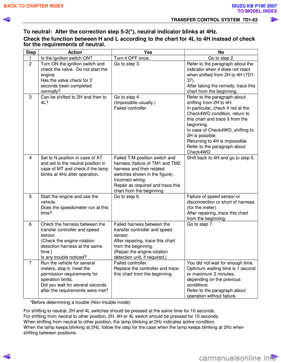
To neutral: After the correction step 5-2(*), neutral indicator blinks at 4Hz.
Check the function between H and L according to the chart for 4L to 4H instead of check
for the requirements of neutral.
Step Action Yes No
1 Is the ignition switch ON? Turn it OFF once. Go to step 2.
2 Turn ON the ignition switch and
check the valve. Do not start the
engine.
Has the valve check for 2
seconds been completed
normally? Go to step 3.
Refer to the paragraph about the
indicator when it does not react
when shifted from 2H to 4H (7D1-
37).
After taking the remedy, trace this
chart from the beginning.
3 Can be shifted to 2H and then to 4L? Go to step 4.
(Impossible usually.)
Failed controller Refer to the paragraph about
shifting from 2H to 4H.
In particular, check if not at the
Check4W D condition, return to
this chart and trace it from the
beginning.
In case of Check4W D, shifting to
2H is possible.
Returning to 4H is impossible.
Refer to the paragraph about
Check4W D.
4 Set to N position in case of AT and set to the neutral position in
case of MT and check if the lamp
blinks at 4Hz after operation. Failed T/M position switch and
harness (failure of TM1 and TM2
harness and their related
switches shown in the figure).
Incorrect wiring.
Repair as required and trace this
chart from the beginning. Shift back to 4H and go to step 5.
5 Start the engine and use the
vehicle.
Does the speedometer run at this
time? Go to step 6.
Failure of speed sensor or
disconnection or short of harness
(for the meter).
After repairing, trace this chart
from the beginning.
6 Check the harness between the transfer controller and speed
sensor.
(Check the engine rotation
detection harness at the same
time.)
Is any trouble noticed? Failed harness between the
transfer controller and speed
sensor.
After repairing, trace this chart
from the beginning.
(Repair the engine rotation
detection unit, if required.) Go to step 7.
7 Run the vehicle for several
meters, stop it, meet the
permission requirements for
operation limits.
Did you wait for several seconds
after the requirements were met? Failed controller.
Replace the controller and trace
this chart from the beginning. You did not wait for enough time.
Optimum waiting time is 1 second
or maximum 3 minutes,
depending on the previous
conditions.
Refer to the paragraph about
operation without failure.
*Before determining a trouble (Non-trouble mode)
For shifting to neutral, 2H and 4L switches should be pressed at the same time for 10 seconds.
For shifting from neutral to other position, 2H, 4H or 4L switch should be pressed for 10 seconds.
W hen shifting from neutral to other position, the lamp blinking at 2Hz indicates active condition.
W hen the lamp keeps blinking at 2Hz, follow the step for the case when the lamp keeps blinking at 2Hz when
shifting between positions.
BACK TO CHAPTER INDEX
TO MODEL INDEX
ISUZU KB P190 2007
Page 5181 of 6020
ELECTRICAL-BODY AND CHASSIS 8A-243
RTW 78ASH002001
A Type
RTW 78ASH002101
3. Push the horn switch area1 and area-2. At that time check
the audible noise from each snap stud. (Should be no noise
present)
4. Enable the SRS (Refer to “Enabling the SRS” in Section 9A).
B Type
RTW 780SH003101
INSPECTION AND REPAIR
Switch side Harness side
B60 B60
TURN SIGNAL SWITCH
Lighting Switch Connections
Terminal No.
SW position 5 6 7
Left
Neutral
Right
Turning
direction
BACK TO CHAPTER INDEX TO MODEL INDEXISUZU KB P190 2007
Page 5552 of 6020
8A-614 ELECTRICAL-BODY AND CHASSIS
No. Connector face No. Connector face
C106
NOT USED C117
Black
Anti theft horn
C107
White
J/B E2 C118
A/C Resister & Neutral switch
C108
White
J/B E1 C119
~
C120 NOT USED
C109
Silver
Body-CTR; ground C121
(C24SE)
IAT sensor
C110
NOT USED C122
(C24SE)
White
Co adjuster connector
C111
Black
Transfer case control module C123
NOT USED
C112
Black
Transfer case control module C124
BlackLower pressure sensor
C113
~
C114 NOT USED C125
White
Thermo switch (Air)
C115
Brown
EVRV EGR C126
WhiteGlow control unit
C116
Black
MAF sensor C127
~
C130 NOT USED
BACK TO CHAPTER INDEX
TO MODEL INDEXISUZU KB P190 2007
Page 5557 of 6020
ELECTRICAL-BODY AND CHASSIS 8A-619
No. Connector face No. Connector face
E1
Gray
Oil pressure switch E9
Gray
T.D.C sensor
E2
(C24SE)
Magnetic clutch E10
SilverEngine ground
E3
Black
Magnetic clutch AC COMP E11
Natural greenNeutral switch
E4
Green
Generator E12
Natural greenNeutral switch
E5
TPS EGR E13
Gray Injector nozzle 1
E6
(C24SE)
Fuel injector (C24SE) E14
Gray
Injector nozzle 2
E6
Injector pump E15
Gray Injector nozzle 3
E7
(C24SE)
Fuel injector (C24SE) E16
Gray
Injector nozzle 4
E8
(C24SE)
Fuel injector (C24SE) E17
Silver
Generator (B)
E9
(C24SE)
Fuel injector (C24SE) E18
(C24SE)
Ignition coil
BACK TO CHAPTER INDEX TO MODEL INDEXISUZU KB P190 2007
Page 5559 of 6020
ELECTRICAL-BODY AND CHASSIS 8A-621
No. Connector face No. Connector face
E44
Black
Vehicle speed sensor E53
NOT USED
E45
Gray
2W D-4W D switch E54
A/T term ASM (AW 30-40LE)
E46
Brown
H-L neutral switch E54
BlackA/T term ASM (JR405E)
E47
Black
MAF & IAT sensor E55
~
E58 NOT USED
E48
Black
Fuel rail pressure sensor E59
(C24SE)
Crank position sensor (C24SE)
E49
Silver
Glow plug E60
(C24SE)
ECM
E50
Gray
Suction control valve (SVC) E61
~
E63 NOT USED
E51
Gray
Inhibiter switch (AW 30-40LE) E64
(C24SE)
Oil pressure switch (P/STRG)
E51
Black
Inhibitor switch (JR405E) E65
(C24SE)
Thermo unit
E52
Black
Crankshaft position (CKP) sensor E66
(C24SE)
Duty solenoid
BACK TO CHAPTER INDEX TO MODEL INDEXISUZU KB P190 2007
Page 5561 of 6020
ELECTRICAL-BODY AND CHASSIS 8A-623
No. Connector face No. Connector face
E89
White
Immobilizer engine control unit E107
MAP sensor
E90
Black
ECM J1 E108
Blue Cylinder revolution
E92
Silver
Fuse & relay box E109
Blue SPGA
E94
~
E95 NOT USED E110
Brown
Backup light switch
E96
Black
Reverse switch E111
BrownNeutral switch
E97
~
E98 NOT USED E112
Gray
1st switch
E99
Black
O2 sensor-RH E113
Gray Clutch sleave cylinder
E100
Black
O2 sensor-LH E114
~
E115 NOT USED
E101
~
E105 NOT USED E116
Backup light switch
E106
EVRV: Turbo
BACK TO CHAPTER INDEX
TO MODEL INDEXISUZU KB P190 2007
Page 5567 of 6020
ELECTRICAL-BODY AND CHASSIS 8A-629
No. Connector face No. Connector face
M26
(C24SE)
Brown
2W D-4W D switch
M27
(C24SE)
Brown
Headlight leveling neutral switch
BACK TO CHAPTER INDEX
TO MODEL INDEXISUZU KB P190 2007
Page 5593 of 6020

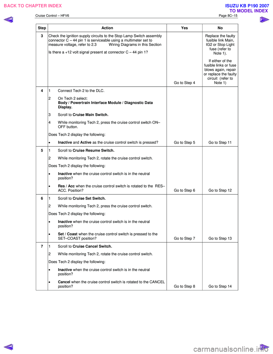
Cruise Control – HFV6 Page 8C–15
Step Action Yes No
3 Check the ignition supply circuits to the Stop Lamp Switch assembly
connector C – 44 pin 1 is serviceable using a multimeter set to
measure voltage, refer to 2.3 W iring Diagrams in this Section
Is there a +12 volt signal present at connector C – 44 pin 1?
Go to Step 4 Replace the faulty
fusible link Main,
IG2 or Stop Light fuse (refer to Note 1).
If either of the
fusible links or fuse blows again, repair
or replace the faulty circuit (refer to
Note 1)
4 1 Connect Tech 2 to the DLC.
2 On Tech 2 select: Body / Powertrain Interface Module / Diagnostic Data
Display.
3 Scroll to Cruise Main Switch.
4 W hile monitoring Tech 2, press the cruise control switch ON– OFF button.
Does Tech 2 display the following:
• Inactive and Active as the cruise control switch is pressed?
Go to Step 5 Go to Step 11
5 1 Scroll to Cruise Resume Switch.
2 While monitoring Tech 2, rotate the cruise control switch.
Does Tech 2 display the following:
• Inactive when the cruise control switch is in the neutral
position?
• Res / Acc when the cruise control switch is rotated to the RES–
ACC. Position? Go to Step 6 Go to Step 12
6
1 Scroll to Cruise Set Switch.
2 W hile monitoring Tech 2, press the cruise control switch.
Does Tech 2 display the following:
• Inactive when the cruise control switch is in the neutral
position?
• Set / Coast when the cruise control switch is pressed to the
SET–COAST position? Go to Step 7 Go to Step 13
7 1 Scroll to Cruise Cancel Switch.
2 While monitoring Tech 2, rotate the cruise control switch.
Does Tech 2 display the following:
• Inactive when the cruise control switch is in the neutral
position?
• Cancel when the cruise control switch is rotated to the CANCEL
position? Go to Step 8 Go to Step 14
BACK TO CHAPTER INDEX
TO MODEL INDEXISUZU KB P190 2007