Page 4558 of 6020
UNIT REPAIR (JR405E) 7A4-81
244L300001
21.Oil pan
• Install a new gasket and the oil pan.
• Tighten the bolts to the specified torque.
Torque: 8 N ⋅
⋅⋅
⋅
m (0.8 kgf ⋅
⋅⋅
⋅
m/69 lb ⋅
⋅⋅
⋅
in)
47INH-SW 01
22.Inhibitor switch
• Secure the inhibitor switch (1) by hand-tightening the 2
bolts.
• Use the inhibitor switch set plate to align the neutral
holes (manual shaft and inhibitor switch).
Turn the inhibitor switch to adjust it.
Inhibitor switch set plate: 5-8840-2763-0
NOTE:
Inhibitor switch adjustment is very important.
If the inhibitor switch is not correctly adjusted, the
automatic transmission will not function normally.
• Tighten the 2 inhibitor switch bolts to the specified
torque.
BACK TO CHAPTER INDEX
TO MODEL INDEX
ISUZU KB P190 2007
Page 4615 of 6020
MANUAL TRANSMISSION 7B1-9
6. Remove the gear control lever.
7. Raise and support the vehicle with suitable stands.
8. Remove the rear propeller shaft.
NOTE: Apply alignment marks on the flange at the
differential side.
401RS023
9. Loosen the front exhaust pipe fixing nuts at the engine side but do not remove them. (Diesel engine
only)
RTW 67BSH000101
10. Disconnect the harness connectors and clips on the
transmission.
• Neutral Switch
• Back up Switch
• Car Speed Sensor
11. Remove the fuel pipe bracket with pipes from the transmission.
Diesel engine
220R300012
Legend
(1) Bolt
(2) Nut
(3) Fuel Pipe Assembly
C24SE
Scan-1
BACK TO CHAPTER INDEX
TO MODEL INDEX
ISUZU KB P190 2007
Page 4620 of 6020

7B1-14 MANUAL TRANSMISSION
5. Install the starter. (Diesel engine only)
NOTE: Tighten the lower bolt temporarily.
After installing the fuel pipe assembly, tighten the bolt to
the specified torque.
Torque: 76 N ⋅
⋅⋅
⋅
m (7.7 kgf ⋅
⋅⋅
⋅
m/56 lb ⋅
⋅⋅
⋅
ft)
6. Install the rear support rubber on the transmission and tighten the nuts to the specified torque.
Torque: 52 N ⋅
⋅⋅
⋅
m (5.3 kgf ⋅
⋅⋅
⋅
m/38 lb ⋅
⋅⋅
⋅
ft)
7. Install the middle part of the transmission crossmember and the bolts.
Tighten the nuts to the specified torque.
Torque: 67 N ⋅
⋅⋅
⋅
m (6.8 kgf ⋅
⋅⋅
⋅
m/49 lb ⋅
⋅⋅
⋅
ft)
8. Install the engine rear mount nuts fixing on the transmission crossmember.
Torque: 52 N ⋅
⋅⋅
⋅
m (5.3 kgf ⋅
⋅⋅
⋅
m/38 lb ⋅
⋅⋅
⋅
ft)
Remove the transmission jack from transmission
side.
9. Apply grease to the top hole portion of the shift fork. Install the slave cylinder and tighten the bolts to the
specified torque.
Torque: 76 N ⋅
⋅⋅
⋅
m (7.7 kgf ⋅
⋅⋅
⋅
m/56 lb ⋅
⋅⋅
⋅
ft)
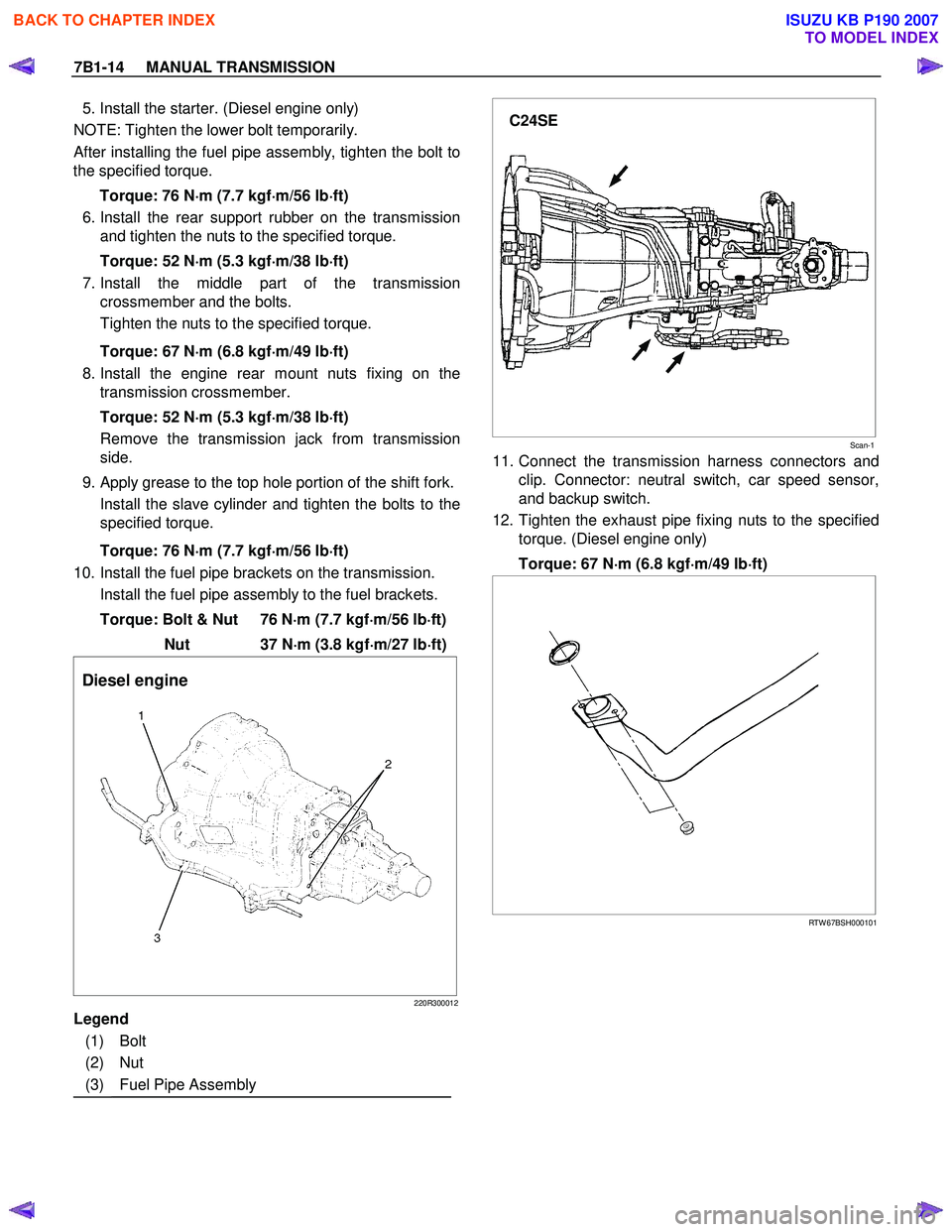
10. Install the fuel pipe brackets on the transmission.
Install the fuel pipe assembly to the fuel brackets.
Torque: Bolt & Nut 76 N ⋅
⋅⋅
⋅
m (7.7 kgf ⋅
⋅⋅
⋅
m/56 lb ⋅
⋅⋅
⋅
ft)
Nut 37 N ⋅
⋅⋅
⋅
m (3.8 kgf ⋅
⋅⋅
⋅
m/27 lb ⋅
⋅⋅
⋅
ft)
Diesel engine
220R300012
Legend
(1) Bolt
(2) Nut
(3) Fuel Pipe Assembly
C24SE
Scan-1
11. Connect the transmission harness connectors and
clip. Connector: neutral switch, car speed sensor,
and backup switch.
12. Tighten the exhaust pipe fixing nuts to the specified torque. (Diesel engine only)
Torque: 67 N ⋅
⋅⋅
⋅
m (6.8 kgf ⋅
⋅⋅
⋅
m/49 lb ⋅
⋅⋅
⋅
ft)
RTW 67BSH000101
BACK TO CHAPTER INDEX
TO MODEL INDEX
ISUZU KB P190 2007
Page 4669 of 6020
MANUAL TRANSMISSION 7B1-63
6. Remove the gear control lever.
7. Raise and support the vehicle with suitable stands.
8. Remove the rear propeller shaft.
NOTE: Apply alignment marks on the flange at the
differential side.
9. Remove the front propeller shaft.
NOTE:
Apply alignment marks on the flange at both
front and rear sides.
401RS023
10. Loosen the front exhaust pipe fixing nuts at the engine side but do not remove them. (Diesel engine
only)
RTW 67BSH000101
11. Disconnect the harness connectors and clips on the
transmission and transfer.
• Neutral Switch: Transmission
• Back up Switch
• Actuator
• 2W D-4W D Switch
• Neutral Switch: Transfer
• Car Speed Sensor
810R300069
Legend
(1) Neutral Switch Connector: Transmission
(2) Back up Switch Connector
(3) Speed Sensor Connector
(4) Actuator Connector
(5) 2W D - 4W D Switch Connector
(6) Neutral Switch Connector: Transfer
BACK TO CHAPTER INDEX
TO MODEL INDEX
ISUZU KB P190 2007
Page 4675 of 6020

MANUAL TRANSMISSION 7B1-69
8. Install the starter. (Diesel engine)
NOTE: Tighten the lower bolt temporarily.
After installing the fuel pipe assembly, tighten the bolt to
the specified torque.
Torque: 76 N ⋅
⋅⋅
⋅
m (7.7 kgf ⋅
⋅⋅
⋅
m/56 lb ⋅
⋅⋅
⋅
ft)
9. Install the rear support rubber on the transmission and tighten the bolts to the specified torque.
Torque: 50 N ⋅
⋅⋅
⋅
m (5.1 kgf ⋅
⋅⋅
⋅
m/37 lb ⋅
⋅⋅
⋅
ft)
10. Install the middle part of transmission crossmember and bolts.
Tighten the nuts to the specified torque.
Torque: 67 N ⋅
⋅⋅
⋅
m (6.8 kgf ⋅
⋅⋅
⋅
m/49 lb ⋅
⋅⋅
⋅
ft)
11. Install the engine rear mount nuts.
Torque: 52 N ⋅
⋅⋅
⋅
m (5.3 kgf ⋅
⋅⋅
⋅
m/38 lb ⋅
⋅⋅
⋅
ft)
Remove the transmission jack from the
transmission side.
12. Apply grease to top hole portion of the shift fork. Install the slave cylinder and tighten the bolts to the
specified torque.
Torque: 76 N ⋅
⋅⋅
⋅
m (7.7 kgf ⋅
⋅⋅
⋅
m/56 lb ⋅
⋅⋅
⋅
ft)
13. Install the fuel pipe brackets on the transmission.
Install the fuel pipe assembly to the fuel pipe brackets
Torque: Bolt & Nut 76 N ⋅
⋅⋅
⋅
m (7.7 kgf ⋅
⋅⋅
⋅
m/56 lb ⋅
⋅⋅
⋅
ft)
Nut 37 N ⋅
⋅⋅
⋅
m (3.8 kgf ⋅
⋅⋅
⋅
m/27 lb ⋅
⋅⋅
⋅
ft)
Diesel engine
220R300012
Legend
(1) Bolt
(2) Nut
(3) Fuel Pipe Assembly
C24SE
Scan-2
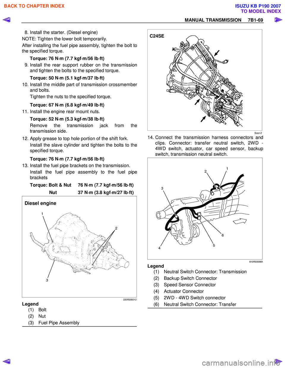
14. Connect the transmission harness connectors and
clips. Connector: transfer neutral switch, 2W D -
4W D switch, actuator, car speed sensor, backup
switch, transmission neutral switch.
810R300069
Legend
(1) Neutral Switch Connector: Transmission
(2) Backup Switch Connector
(3) Speed Sensor Connector
(4) Actuator Connector
(5) 2W D - 4W D Switch connector
(6) Neutral Switch Connector: Transfer
BACK TO CHAPTER INDEX
TO MODEL INDEX
ISUZU KB P190 2007
Page 4728 of 6020
Manual Transmission (MUX) 7B1-9
• Apply alignment marks on the flange at thedifferential side.
9. Remove the front propeller shaft. (4x4 model) • Apply alignment marks on the flange at bothfront and rear side. 10. Disconnect the harness connectors and clips on
the transmission.
Legend 1. Neutral switch connector
2. Clutch damper valve connector
Legend 3. Clip
4. Reverse switch connector
5. 1st switch connector
RTW77BSH000201
RTW77BSH000201
RTW77BSH006601
1
2
RTW77BSH006701
3
3 54
BACK TO CHAPTER INDEX
TO MODEL INDEX
ISUZU KB P190 2007
Page 4729 of 6020

7B1-10 Manual Transmission (MUX)
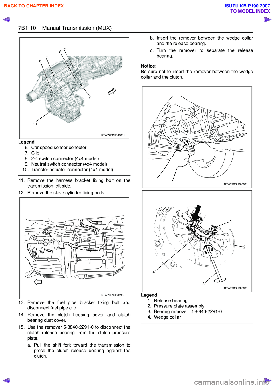
Legend6. Car speed sensor conector
7. Clip
8. 2-4 switch connector (4x4 model)
9. Neutral switch connector (4x4 model)
10. Transfer actuator connector (4x4 model)
11. Remove the harness bracket fixing bolt on the transmission left side.
12. Remove the slave cylinder fixing bolts.
13. Remove the fuel pipe bracket fixing bolt and disconnect fuel pipe clip.
14. Remove the clutch housing cover and clutch bearing dust cover.
15. Use the remover 5-8840-2291-0 to disconnect the clutch release bearing from the clutch pressure
plate.
a. Pull the shift fork toward the transmission to press the clutch release bearing against the
clutch. b. Insert the remover between the wedge collar
and the release bearing.
c. Turn the remover to separate the release bearing.
Notice:
Be sure not to insert the remover between the wedge
collar and the clutch.
Legend 1. Release bearing
2. Pressure plate assembly
3. Bearing remover : 5-8840-2291-0
4. Wedge collar
RTW77BSH006801
10 9
6
7 8
7
RTW77BSH000301
RTW77BSH000801
RTW77BSH000601
1
3
4
2
BACK TO CHAPTER INDEX
TO MODEL INDEX
ISUZU KB P190 2007
Page 4732 of 6020
Manual Transmission (MUX) 7B1-13
16. Install the front propeller shaft. (4x4 model)• Tighten the front propeller shaft bolts to thespecified torque.
Torque: 59 N ⋅m (6.0 kgf ⋅m/43 lb ⋅ft)
17. Install the rear propeller shaft.
• Tighten the rear propeller shaft bolts to thespecified torque.
Torque
Rear flange: 59 N ⋅m (6.0 kgf ⋅m/43 lb ⋅ft)
Center bearing: 69 N ⋅m (7.0 kgf ⋅m/51 lb ⋅ft)
18. Connect harness clip on the transmission left side bracket.
Install the harness bracket bolt.
• Tighten the harness bracket bolt to the specified torque.
Torque: 23 N ⋅m (2.3 kgf ⋅m/17 lb ⋅ft) 19. Connect the harness connectors and clips on the
transmission.
Legend 1. Neutral switch connector
2. Clutch damper valve connector
Legend 3. Clip
4. Reverse switch connector
5. 1st switch connector
RTW77BSH000301
RTW77BSH006601
1
2
RTW77BSH006701
3
3 54
BACK TO CHAPTER INDEX
TO MODEL INDEX
ISUZU KB P190 2007