2007 ISUZU KB P190 jack points
[x] Cancel search: jack pointsPage 9 of 6020

GENERAL INFORMATION 0A-7
LIFTING INSTRUCTIONS
If a lifting device other than the original jack is used, it is most important that the device be applied only to the
correct lifting points. (See the illustration.) Raising the vehicle from any other point may result in serious damage.
Lifting Points and Supportable Point-Locations
RTW 50AXF000201
BACK TO CHAPTER INDEX
TO MODEL INDEX
ISUZU KB P190 2007
Page 842 of 6020

ENGINE MECHANICAL 6A – 37
REMOVAL AND INSTALLATION
Read this section carefully before performing any removal and installation procedure. This section gives
you important points as well as the order of operation. Be sure that you understand everything in this section before
you begin.
Removal
P1010011
1. Battery
1) Disconnect the battery cable and the grounding cable from the battery terminals.
2) Remove the battery clamp. Take care not to accidentally short the battery with the wrench or some
other tool.
3) Remove the battery.
4) Disconnect the battery cable at the starter motor and the ground cable at the cylinder body.
2. Engine Hood Apply setting marks to the engine hood and the engine
hood hinges before removing the engine hood. This will
facilitate reinstallation of the engine hood to its original
position.
3. Supporting the Vehicle 1) Jack up the vehicle.
2) Place chassis stands at the front and the rear of the vehicle.
4. Under cover (for 4x4 model) 5. Rear propeller shaft 1) Remove the propeller shaft flange yoke at the rear differential.
2) Remove the center bearing retainer bolts.
3) Remove the propeller shaft together with the center bearing from the transmission mainshaft spline.
F06R300006 P1010002
BACK TO CHAPTER INDEX
TO MODEL INDEX
ISUZU KB P190 2007
Page 2567 of 6020
Engine Mechanical – V6 Page 6A1–88
NOTE
Do not disconnect the A/C compressor pipes.
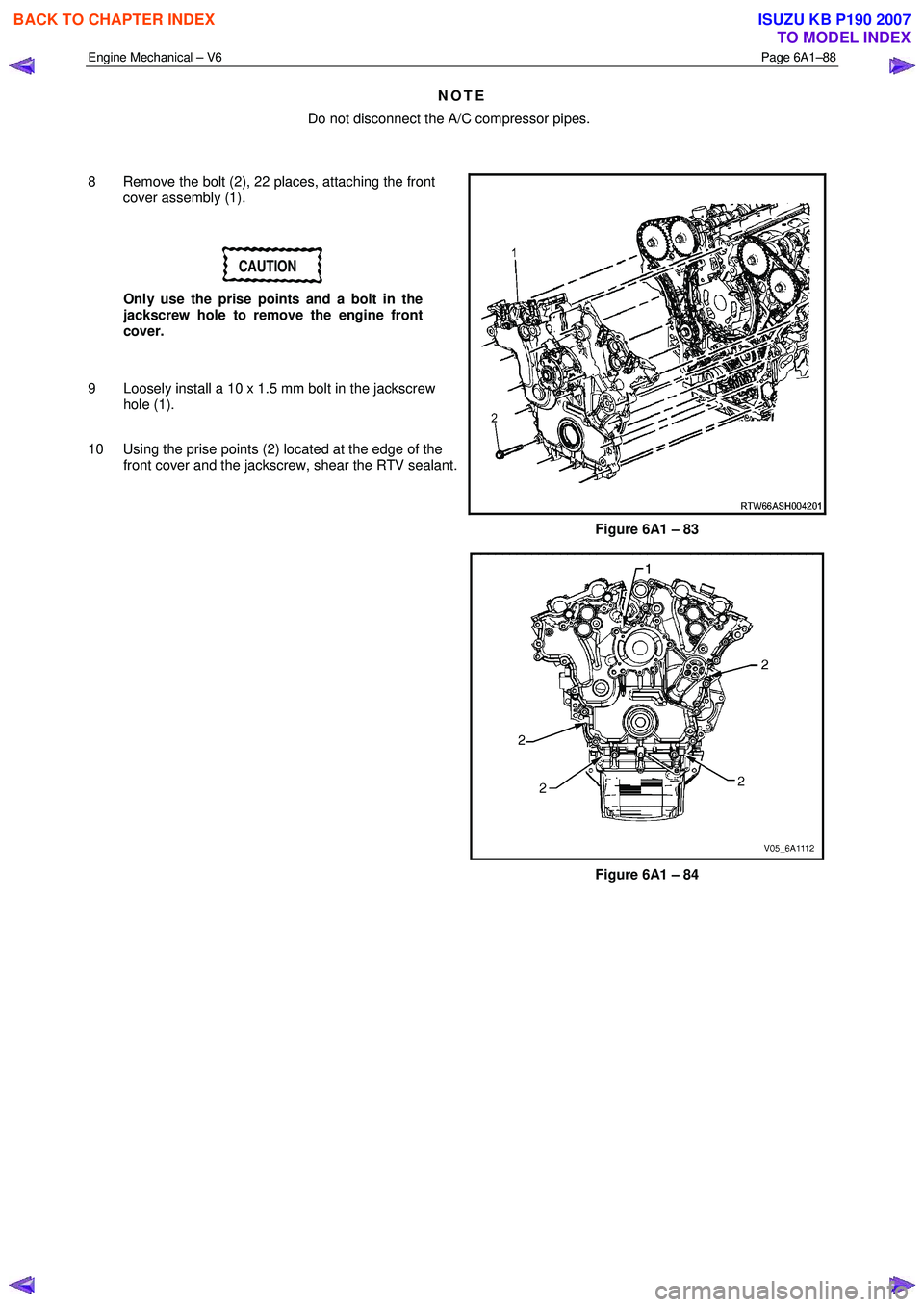
8 Remove the bolt (2), 22 places, attaching the front cover assembly (1).
CAUTION
Only use the prise points and a bolt in the
jackscrew hole to remove the engine front
cover.
9 Loosely install a 10 x 1.5 mm bolt in the jackscrew hole (1).
10 Using the prise points (2) located at the edge of the front cover and the jackscrew, shear the RTV sealant.
Figure 6A1 – 83
Figure 6A1 – 84
BACK TO CHAPTER INDEX
TO MODEL INDEX
ISUZU KB P190 2007
Page 2881 of 6020
Engine Mechanical – V6 Page 6A1–104
Page 6A1–104
3.15 Front Cover Assembly
Remove
1 Drain the engine coolant, refer to Section 6B1 Engine Cooling.
2 Remove the water outlet pipe and coolant pump assembly, refer to Section 6B1 Engine Cooling:
3 Remove the camsha ft covers, refer to 3.12 Camshaft Cover .
4 Remove the crankshaft bal ancer assembly, refer to 3.13 Crankshaft Balancer Assembly .
5 Disconnect the purge vent hose from the water outlet pipe.
NOTE
Do not disconnect the power steering pipes or
drain the power steering fluid.
6 Remove the power steering pump reservoir mounting bracket, refer to 3.8 Power Steering Pump Bracket.
7 Remove the camshaft position sensor, refer to Section 6C1-3 Engine Management – V6 – Service Operations.
NOTE
Do not disconnect the A/C compressor pipes.
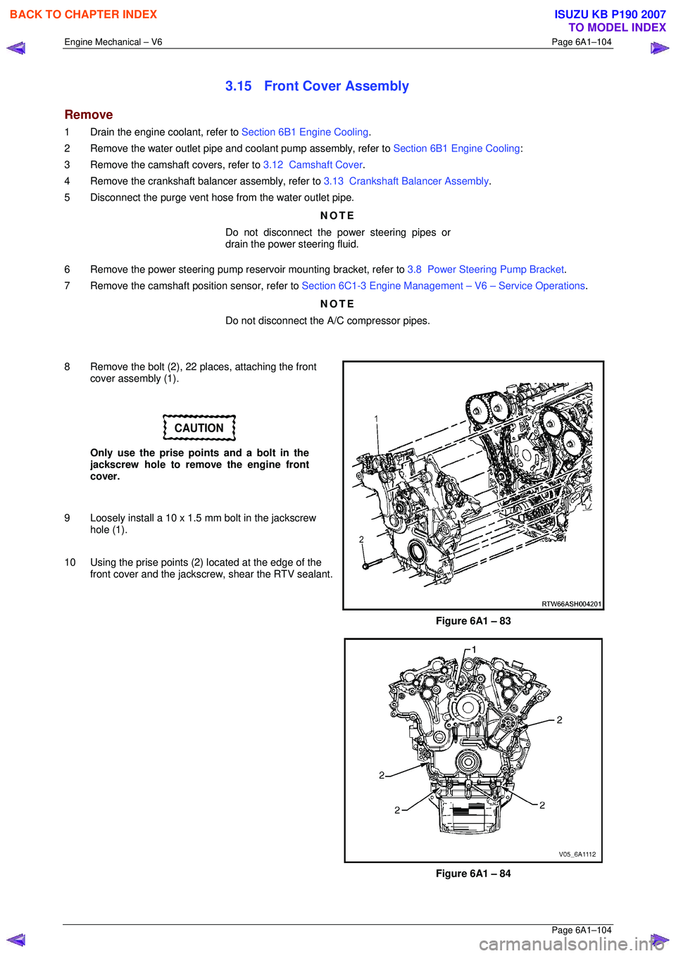
8 Remove the bolt (2), 22 places, attaching the front cover assembly (1).
CAUTION
Only use the prise points and a bolt in the
jackscrew hole to remove the engine front
cover.
9 Loosely install a 10 x 1.5 mm bolt in the jackscrew hole (1).
10 Using the prise points (2) located at the edge of the
front cover and the jackscrew, shear the RTV sealant.
Figure 6A1 – 83
Figure 6A1 – 84
BACK TO CHAPTER INDEX
TO MODEL INDEX
ISUZU KB P190 2007
Page 3182 of 6020
Engine Cooling – V6 Engine Page 6B1–47
Disconnection of the battery affects certain
vehicle electronic systems. Refer to 1.1
WARNING, CAUTION and NOTES, before
removing the ground lead.
2 Disconnect the battery ground lead. Refer to 8A – Electrical Body & Chassis.
Refer to ‘
‘‘
‘
Environmental Issues ’
’’
’
in 3.1
Service Notes, before draining the coolant.
3 Draining the coolant from the system. Refer to 3.3 Draining and Filling Cooling System in this Section.
4 Raise the front of the vehicle and support on safety stands. Refer to 0A General Information for the location of jacking and support points.
Always wear protective safety glasses when
working with spring type hose clamps.
Failure to do so could result in eye injury.
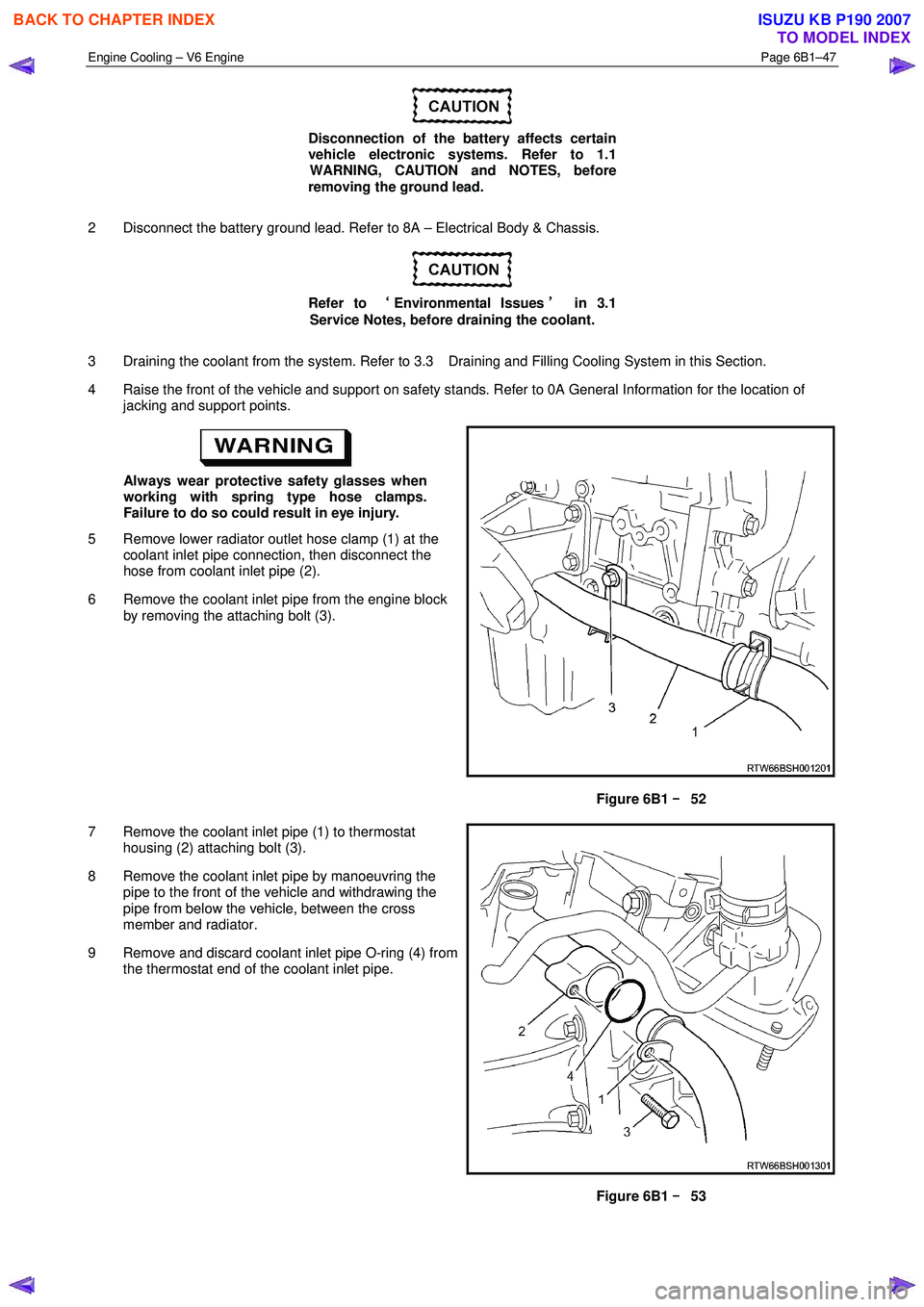
5 Remove lower radiator outlet hose clamp (1) at the coolant inlet pipe connection, then disconnect the
hose from coolant inlet pipe (2).
6 Remove the coolant inlet pipe from the engine block by removing the attaching bolt (3).
Figure 6B1 –
––
–
52
7 Remove the coolant inlet pipe (1) to thermostat housing (2) attaching bolt (3).
8 Remove the coolant inlet pipe by manoeuvring the pipe to the front of the vehicle and withdrawing the
pipe from below the vehicle, between the cross
member and radiator.
9 Remove and discard coolant inlet pipe O-ring (4) from the thermostat end of the coolant inlet pipe.
Figure 6B1 –
––
–
53
BACK TO CHAPTER INDEX
TO MODEL INDEX
ISUZU KB P190 2007
Page 3183 of 6020
Engine Cooling – V6 Engine Page 6B1–48
Install
1 Ensure that the coolant inlet pipe and thermostat housing mating surfaces are clean and dry.
2 Install new O-ring to the coolant inlet pipe.
3 Install coolant inlet pipe at the thermostat housing and secure with the attaching bolt. Tighten all bolts to the correct torque specification.
Coolant inlet pipe to thermostat
housing bolt torque specification ..........................23 N.m
4 Raise the front of the vehicle and support on safety stands. Refer to 0A General Information for the location of jacking and support points.
5 Reinstall the coolant inlet pipe to the engine block and secure with the bolt tightened to the correct torque specification.
Coolant inlet pipe to engine block bolt
torque specification .............................................25 N.m
Always wear protective safety glasses when
working with spring type hose clamps. Failure
to do so could result in eye injury.
6 Connect the lower radiator outlet hose and clamp to the coolant inlet pipe connection.
7 Close the radiator drain tap on the lower RHS of the radiator and remove the piece of rubber tubing to the tap outlet.
8 Lower the front of the vehicle.
9 Refill cooling system. Refer to 3.3 Draining and Filling Cooling System in this Section.
10 Check for coolant leaks. Refer to 3.7 Pressure Testing in this Section.
11 Reconnect battery ground lead. Refer to 8A – Electrical Body & Chassis.
3.13 Cooling Fan and Shroud Assembly
Remove
Disconnection of the battery affects certain
vehicle electronic systems. Refer to 1.1
WARNING, CAUTION and NOTES, before
removing the ground lead.
1 Disconnect the battery ground lead. Refer to 8A – Electrical Body & Chassis.
2 Remove the intake duct and mass air flow as an assembly. Refer to 6A1 Engine Mechanical.
3 Remove the coolant recovery hose from the fan shroud retaining clip.
BACK TO CHAPTER INDEX
TO MODEL INDEX
ISUZU KB P190 2007
Page 3410 of 6020
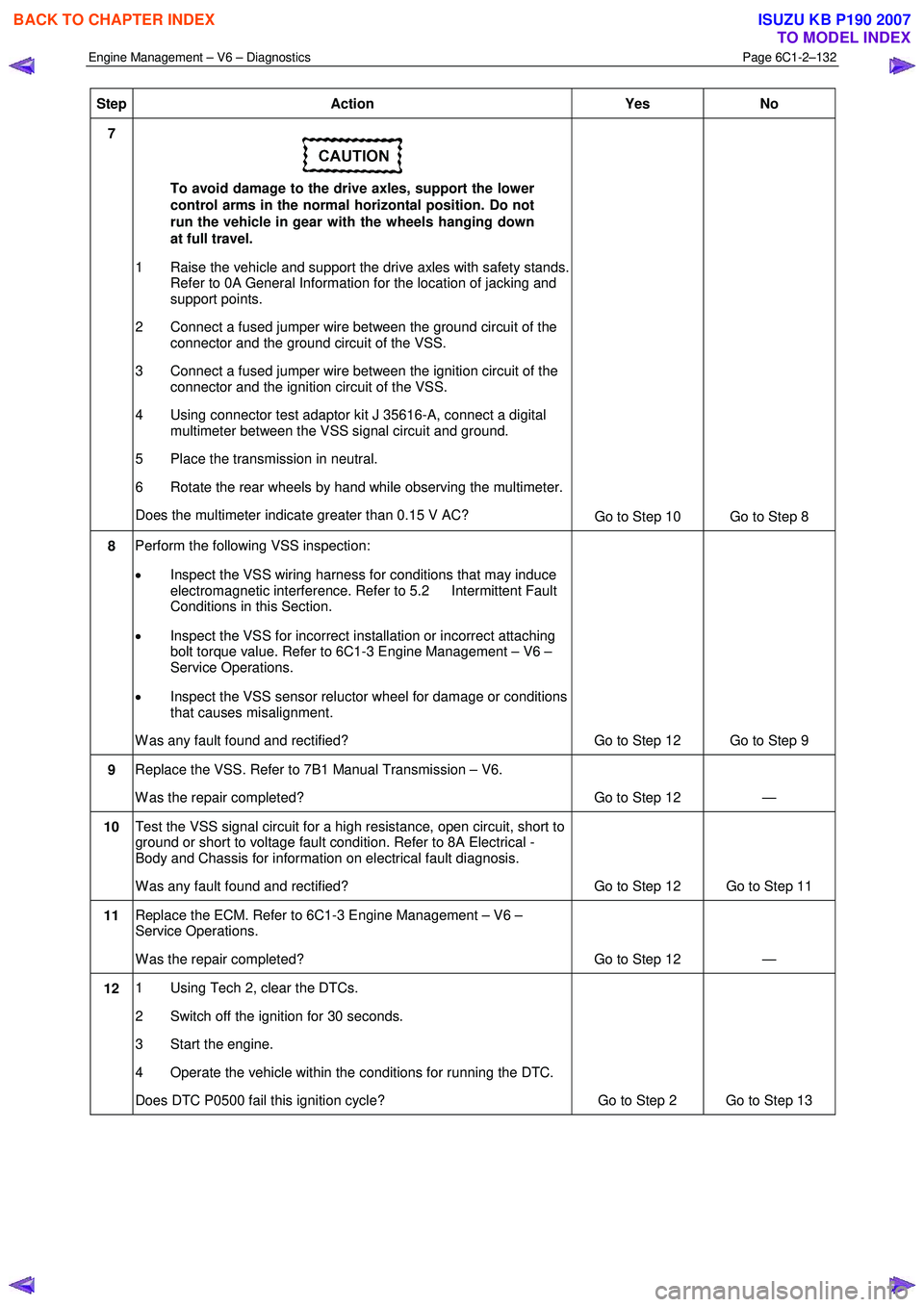
Engine Management – V6 – Diagnostics Page 6C1-2–132
Step Action Yes No
7
To avoid damage to the drive axles, support the lower
control arms in the normal horizontal position. Do not
run the vehicle in gear with the wheels hanging down
at full travel.
1 Raise the vehicle and support the drive axles with safety stands. Refer to 0A General Information for the location of jacking and
support points.
2 Connect a fused jumper wire between the ground circuit of the connector and the ground circuit of the VSS.
3 Connect a fused jumper wire between the ignition circuit of the connector and the ignition circuit of the VSS.
4 Using connector test adaptor kit J 35616-A, connect a digital multimeter between the VSS signal circuit and ground.
5 Place the transmission in neutral.
6 Rotate the rear wheels by hand while observing the multimeter.
Does the multimeter indicate greater than 0.15 V AC? Go to Step 10 Go to Step 8
8 Perform the following VSS inspection:
• Inspect the VSS wiring harness for conditions that may induce
electromagnetic interference. Refer to 5.2 Intermittent Fault
Conditions in this Section.
• Inspect the VSS for incorrect installation or incorrect attaching
bolt torque value. Refer to 6C1-3 Engine Management – V6 –
Service Operations.
• Inspect the VSS sensor reluctor wheel for damage or conditions
that causes misalignment.
W as any fault found and rectified? Go to Step 12 Go to Step 9
9 Replace the VSS. Refer to 7B1 Manual Transmission – V6.
W as the repair completed? Go to Step 12 —
10 Test the VSS signal circuit for a high resistance, open circuit, short to
ground or short to voltage fault condition. Refer to 8A Electrical -
Body and Chassis for information on electrical fault diagnosis.
W as any fault found and rectified? Go to Step 12 Go to Step 11
11 Replace the ECM. Refer to 6C1-3 Engine Management – V6 –
Service Operations.
W as the repair completed? Go to Step 12 —
12 1 Using Tech 2, clear the DTCs.
2 Switch off the ignition for 30 seconds.
3 Start the engine.
4 Operate the vehicle within the conditions for running the DTC.
Does DTC P0500 fail this ignition cycle? Go to Step 2 Go to Step 13
BACK TO CHAPTER INDEX
TO MODEL INDEX
ISUZU KB P190 2007
Page 3537 of 6020
Engine Management – V6 – Service Operations Page 6C1-3–13
Clean the area around the CMP sensor before
removal to avoid debris from entering the
engine.
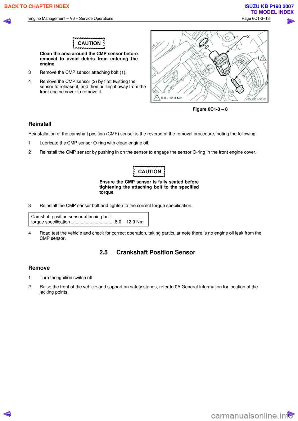
3 Remove the CMP sensor attaching bolt (1).
4 Remove the CMP sensor (2) by first twisting the sensor to release it, and then pulling it away from the
front engine cover to remove it.
Figure 6C1-3 – 8
Reinstall
Reinstallation of the camshaft position (CMP) sensor is the reverse of the removal procedure, noting the following:
1 Lubricate the CMP sensor O-ring with clean engine oil.
2 Reinstall the CMP sensor by pushing in on the sensor to engage the sensor O-ring in the front engine cover.
Ensure the CMP sensor is fully seated before
tightening the attaching bolt to the specified
torque.
3 Reinstall the CMP sensor bolt and tighten to the correct torque specification. Camshaft position sensor attaching bolt
torque specification ...................................8.0 – 12.0 Nm
4 Road test the vehicle and check for correct operation, taking particular note there is no engine oil leak from the CMP sensor.
2.5 Crankshaft Position Sensor
Remove
1 Turn the ignition switch off.
2 Raise the front of the vehicle and support on safety stands, refer to 0A General Information for location of the jacking points.
BACK TO CHAPTER INDEX
TO MODEL INDEX
ISUZU KB P190 2007