2007 ISUZU KB P190 jack points
[x] Cancel search: jack pointsPage 3546 of 6020
Engine Management – V6 – Service Operations Page 6C1-3–22
3 Road test the vehicle and check for correct operation.
2.9 Engine Oil Level and Temperature
Sensor
To avoid personal injury, take care when
draining the engine oil or removing the engine
oil level and temperature sensor whilst the
engine is hot. Allow the engine to cool before
performing this procedure.
Remove
1 Turn the ignition switch off.
2 Raise the front and rear of the vehicle and support on safety stands, refer to 0A General Information for location of the jacking points.
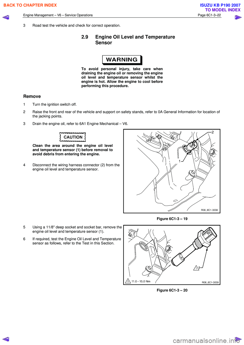
3 Drain the engine oil, refer to 6A1 Engine Mechanical – V6.
Clean the area around the engine oil level
and temperature sensor (1) before removal to
avoid debris from entering the engine.
4 Disconnect the wiring harness connector (2) from the engine oil level and temperature sensor.
Figure 6C1-3 – 19
5 Using a 11/8" deep socket and socket bar, remove the engine oil level and temperature sensor (1).
6 If required, test the Engine Oil Level and Temperature sensor as follows, refer to the Test in this Section.
Figure 6C1-3 – 20
BACK TO CHAPTER INDEX
TO MODEL INDEX
ISUZU KB P190 2007
Page 3558 of 6020
Engine Management – V6 – Service Operations Page 6C1-3–34
• If the HO2S has been removed, but not replaced, anti-seize compound must be applied to the threads prior to
installation. New HO2S will already have the anti-seize compound applied.
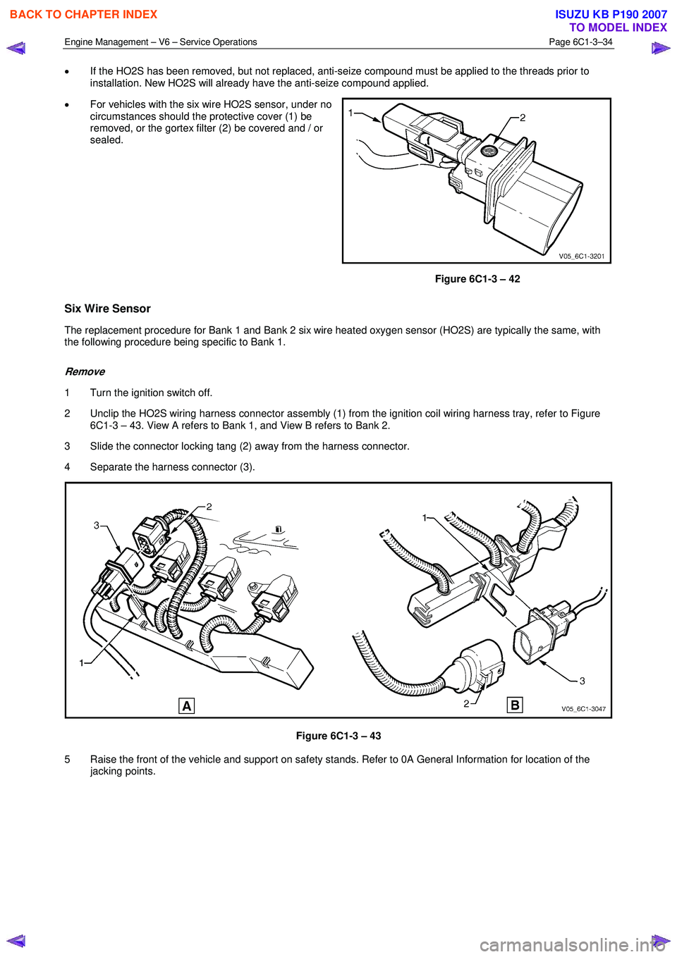
• For vehicles with the six wire HO2S sensor, under no
circumstances should the protective cover (1) be
removed, or the gortex filter (2) be covered and / or
sealed.
Figure 6C1-3 – 42
Six Wire Sensor
The replacement procedure for Bank 1 and Bank 2 six wire heated oxygen sensor (HO2S) are typically the same, with
the following procedure being specific to Bank 1.
Remove
1 Turn the ignition switch off.
2 Unclip the HO2S wiring harness connector assembly (1) from the ignition coil wiring harness tray, refer to Figure 6C1-3 – 43. View A refers to Bank 1, and View B refers to Bank 2.
3 Slide the connector locking tang (2) away from the harness connector.
4 Separate the harness connector (3).
Figure 6C1-3 – 43
5 Raise the front of the vehicle and support on safety stands. Refer to 0A General Information for location of the jacking points.
BACK TO CHAPTER INDEX
TO MODEL INDEX
ISUZU KB P190 2007
Page 3560 of 6020
Engine Management – V6 – Service Operations Page 6C1-3–36
Remove
1 Turn the ignition switch off.
2 Raise the vehicle and support on safety stands, refer to 0A General Information for location of the jacking points.
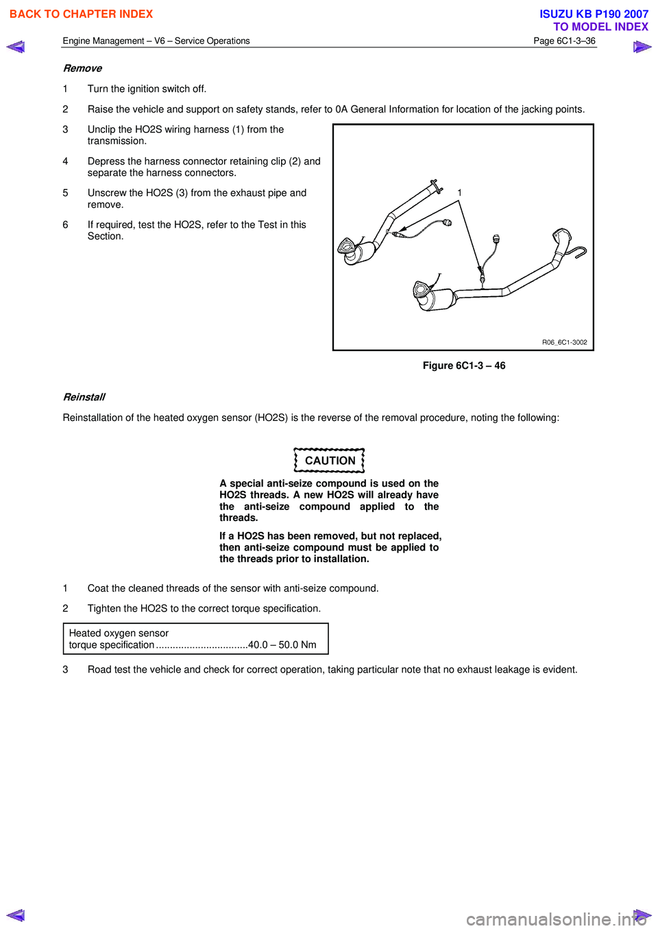
3 Unclip the HO2S wiring harness (1) from the transmission.
4 Depress the harness connector retaining clip (2) and separate the harness connectors.
5 Unscrew the HO2S (3) from the exhaust pipe and remove.
6 If required, test the HO2S, refer to the Test in this Section.
Figure 6C1-3 – 46
Reinstall
Reinstallation of the heated oxygen sensor (HO2S) is the reverse of the removal procedure, noting the following:
A special anti-seize compound is used on the
HO2S threads. A new HO2S will already have
the anti-seize compound applied to the
threads.
If a HO2S has been removed, but not replaced,
then anti-seize compound must be applied to
the threads prior to installation.
1 Coat the cleaned threads of the sensor with anti-seize compound.
2 Tighten the HO2S to the correct torque specification.
Heated oxygen sensor
torque specification .................................40.0 – 50.0 Nm
3 Road test the vehicle and check for correct operation, taking particular note that no exhaust leakage is evident.
BACK TO CHAPTER INDEX
TO MODEL INDEX
ISUZU KB P190 2007
Page 3566 of 6020
Engine Management – V6 – Service Operations Page 6C1-3–42
4 Observe the resistance values as the temperature
increases and compare the temperature / resistance
change to the specifications.
5 If the resistance is not within specifications, replace the MAF sensor.
Intake Air Temperature Vs Resistance
Temperature °C Resistance – Ohms (
Ω)
-40 35140 – 43760
-20 12660 – 15120
-10 7943 – 9307
0 5119 – 5892
20 2290 – 2551
25 1900 – 2100
40 1096 – 1238
60 565 – 654
80 312 – 370
100 184 – 222
120 114 – 141
140 74 – 93
2.18 Knock Sensor, Bank 2 (LHS)
Remove
1 Turn the ignition switch off.
2 Disconnect Bank 2 pre-catalytic converter HO2S wiring harness connector, refer to 2.14 Heated Oxygen Sensor.
3 Raise the front of the vehicle and support on safety stands. Refer to 0A General Information for location of the jacking points.
4 Remove the starter motor heat shield, refer to 6D1-2 Starting System – V6.
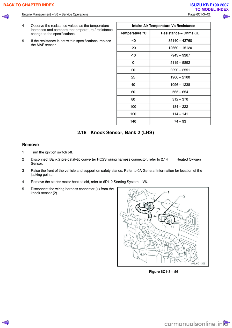
5 Disconnect the wiring harness connector (1) from the knock sensor (2).
Figure 6C1-3 – 56
BACK TO CHAPTER INDEX
TO MODEL INDEX
ISUZU KB P190 2007
Page 3567 of 6020
Engine Management – V6 – Service Operations Page 6C1-3–43
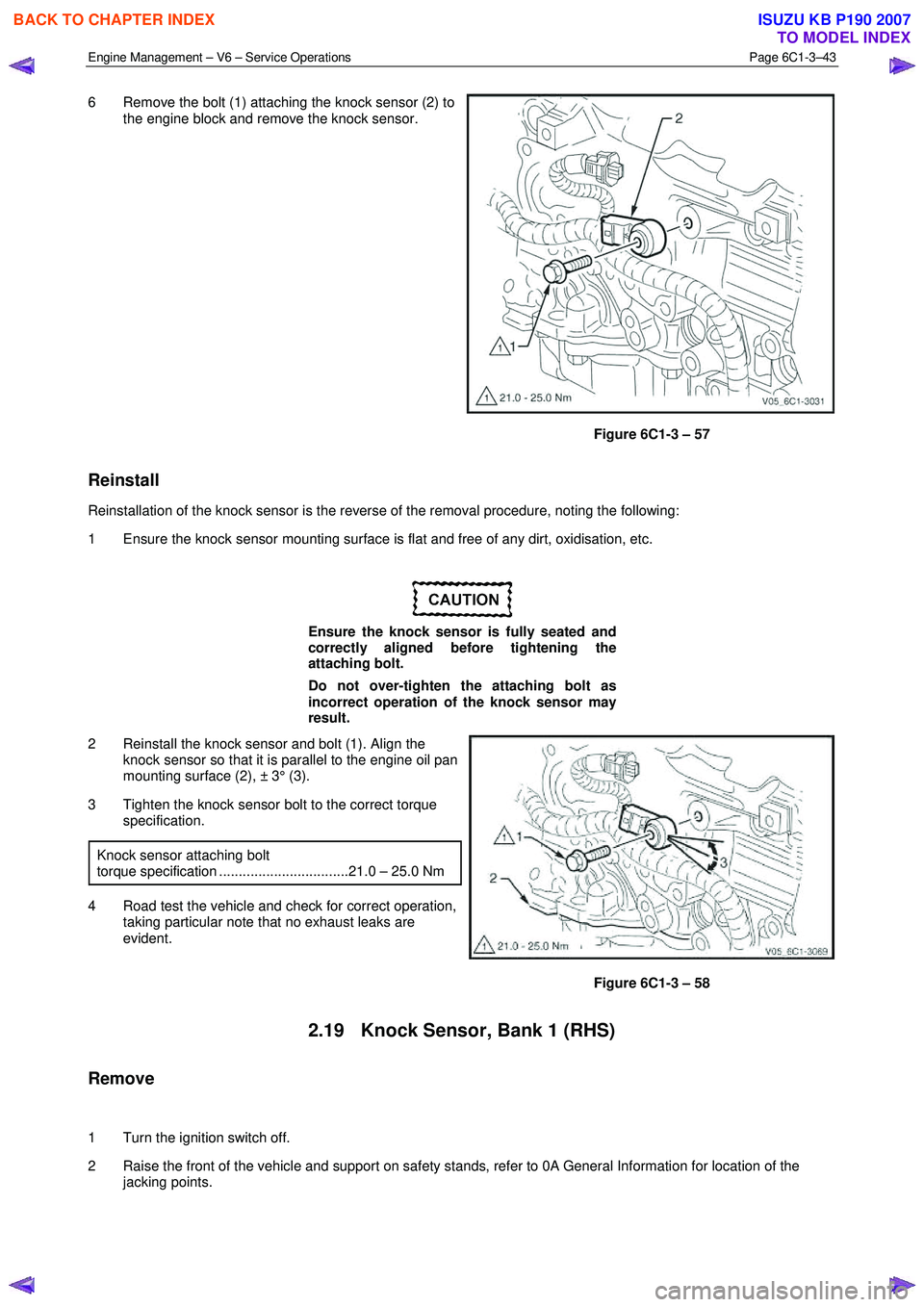
6 Remove the bolt (1) attaching the knock sensor (2) to
the engine block and remove the knock sensor.
Figure 6C1-3 – 57
Reinstall
Reinstallation of the knock sensor is the reverse of the removal procedure, noting the following:
1 Ensure the knock sensor mounting surface is flat and free of any dirt, oxidisation, etc.
Ensure the knock sensor is fully seated and
correctly aligned before tightening the
attaching bolt.
Do not over-tighten the attaching bolt as
incorrect operation of the knock sensor may
result.
2 Reinstall the knock sensor and bolt (1). Align the knock sensor so that it is parallel to the engine oil pan
mounting surface (2), ± 3° (3).
3 Tighten the knock sensor bolt to the correct torque specification.
Knock sensor attaching bolt
torque specification .................................21.0 – 25.0 Nm
4 Road test the vehicle and check for correct operation, taking particular note that no exhaust leaks are
evident.
Figure 6C1-3 – 58
2.19 Knock Sensor, Bank 1 (RHS)
Remove
1 Turn the ignition switch off.
2 Raise the front of the vehicle and support on safety stands, refer to 0A General Information for location of the jacking points.
BACK TO CHAPTER INDEX
TO MODEL INDEX
ISUZU KB P190 2007
Page 3933 of 6020
Automatic Transmission – 4L60E – On-vehicle Servicing Page 7C4–20
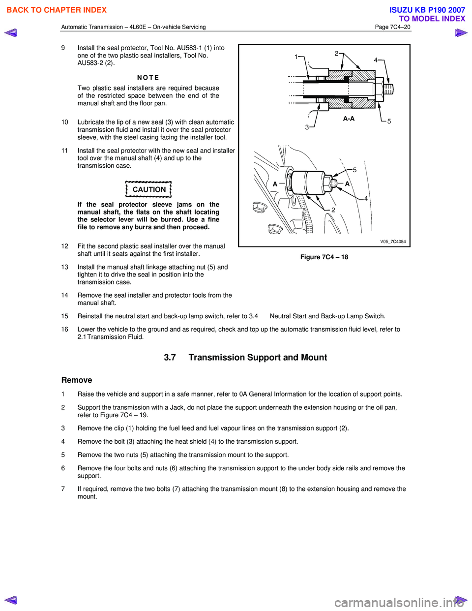
9 Install the seal protector, Tool No. AU583-1 (1) into
one of the two plastic seal installers, Tool No.
AU583-2 (2).
NOTE
Two plastic seal installers are required because
of the restricted space between the end of the
manual shaft and the floor pan.
10 Lubricate the lip of a new seal (3) with clean automatic transmission fluid and install it over the seal protector
sleeve, with the steel casing facing the installer tool.
11 Install the seal protector with the new seal and installer tool over the manual shaft (4) and up to the
transmission case.
If the seal protector sleeve jams on the
manual shaft, the flats on the shaft locating
the selector lever will be burred. Use a fine
file to remove any burrs and then proceed.
12 Fit the second plastic seal installer over the manual shaft until it seats against the first installer.
13 Install the manual shaft linkage attaching nut (5) and tighten it to drive the seal in position into the
transmission case.
14 Remove the seal installer and protector tools from the manual shaft.
Figure 7C4 – 18
15 Reinstall the neutral start and back-up lamp switch, refer to 3.4 Neutral Start and Back-up Lamp Switch.
16 Lower the vehicle to the ground and as required, check and top up the automatic transmission fluid level, refer to 2.1 Transmission Fluid.
3.7 Transmission Support and Mount
Remove
1 Raise the vehicle and support in a safe manner, refer to 0A General Information for the location of support points.
2 Support the transmission with a Jack, do not place the support underneath the extension housing or the oil pan, refer to Figure 7C4 – 19.
3 Remove the clip (1) holding the fuel feed and fuel vapour lines on the transmission support (2).
4 Remove the bolt (3) attaching the heat shield (4) to the transmission support.
5 Remove the two nuts (5) attaching the transmission mount to the support.
6 Remove the four bolts and nuts (6) attaching the transmission support to the under body side rails and remove the support.
7 If required, remove the two bolts (7) attaching the transmission mount (8) to the extension housing and remove the mount.
BACK TO CHAPTER INDEX
TO MODEL INDEX
ISUZU KB P190 2007
Page 4571 of 6020
MSG MODEL 7B-7
REMOVAL AND INSTALLATION
Read this Section carefully before performing any removal and installation procedure. This Section gives you
important points as well as the order of operation. Be sure that you understand everything in this Section before you
begin.
Important Operations - Removal
Battery Cable
Disconnect the negative (-) cable from the battery terminal.
Engine Hood
Apply setting marks to the engine hood and the engine hood
hinges before removing the engine hood.
Gear Shift Lever
1. Place the gear shift lever in the neutral position.
2. Remove the gear shift lever knob.
3. Remove the front console assembly.
4. Remove the gear shift lever grommet and dust cover.
5. Remove the gear shift lever cover bolts.
6. Remove the gear shift lever.
Note:
Cover the shift lever hole to prevent the entry of foreign
material into the transmission.
Lifting the Vehicle
1. Jack up the vehicle.
2. Place chassis stands at the front and the rear of the vehicle.
Transmission Oil Draining
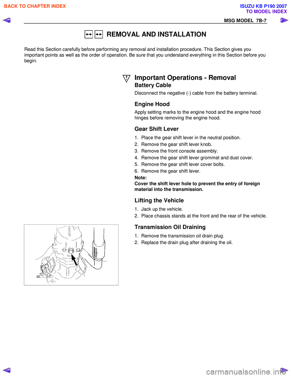
1. Remove the transmission oil drain plug.
2. Replace the drain plug after draining the oil.
BACK TO CHAPTER INDEX
TO MODEL INDEX
ISUZU KB P190 2007
Page 4575 of 6020
MSG MODEL 7B-11
Important Operations - Installation
Follow the removal procedure in the reverse order to perform
the installation procedure.
Pay careful attention to the important points during the
installation procedure.
Transmission
1. Apply a thin coat of molybdenum disulfide grease to the top
gear shaft spline.
2. Place the transmission on a transmission jack.
3. Carefully move the transmission jack and transmission into position behind the engine.
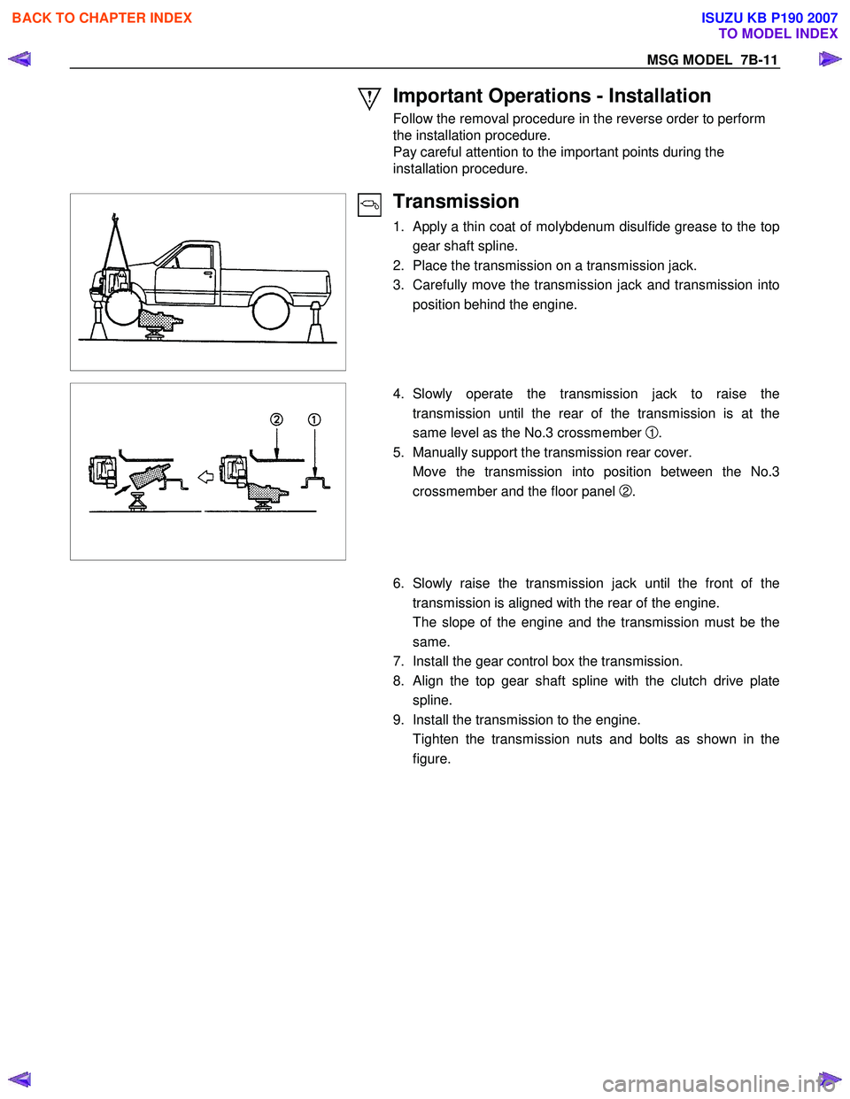
4. Slowly operate the transmission jack to raise the
transmission until the rear of the transmission is at the
same level as the No.3 crossmember
1 .
5. Manually support the transmission rear cover.
Move the transmission into position between the No.3 crossmember and the floor panel
2 .
6. Slowly raise the transmission jack until the front of the
transmission is aligned with the rear of the engine.
The slope of the engine and the transmission must be the same.
7. Install the gear control box the transmission.
8. Align the top gear shaft spline with the clutch drive plate spline.
9. Install the transmission to the engine.
Tighten the transmission nuts and bolts as shown in the figure.
BACK TO CHAPTER INDEX
TO MODEL INDEX
ISUZU KB P190 2007