2007 ISUZU KB P190 run flat
[x] Cancel search: run flatPage 251 of 6020
FRONT ALIGNMENT 3A-3
Inspection
Before making any adjustments affecting caster, camber or
toe-in, the following front end inspection should be made.
1. Inspect the tires for proper inflation pressure. Refer to
Main Data and Specifications in W heel and Tire System section.
2. Make sure that the vehicle is in an unladen condition (W ith no passengers or loading).
3. Make sure that the spare tire is installed at the normal position.
4. Inspect the front wheel bearings for proper adjustment. Refer to Front Hub and Disc Overhaul in Suspension
section.
5. Inspect the ball joints and tie rod ends. If excessive looseness is noted, correct before adjusting. Refer to
Steering Linkage in this section.
6. Inspect the wheel and tires for run-out. Refer to W heel Replacement in W heel and Tire System section.
7. Inspect the trim height. If not within specifications, the correction must be made before adjusting caster.
8. Inspect the steering unit for looseness at the frame.
9. Inspect shock absorbers for leaks or any noticeable noise. Refer to Shock Absorber in Suspension section.
10. Inspect the control arms or stabilizer bar attachment fo
r
looseness. Refer to Suspension section.
11. Inspect the front end alignment using alignment equipment. Follow the manufacturer’s instructions.
12. Park the vehicle on a level surface.
BACK TO CHAPTER INDEX
TO MODEL INDEX
ISUZU KB P190 2007
Page 1489 of 6020
ENGINE MECHANICAL (4JK1/4JJ1) 6A-129
015RY00012
• Install the bearing cap and tighten bolts to the
specified tightening torque.
• Tighten the bearing cap in the sequence shown
using a torque wrench and an angle gauge.
015LX129
Tightening torque: 166 N ⋅
⋅⋅
⋅
m (16.9 kg ⋅
⋅⋅
⋅
m / 122 lb ft)
Note:
Do not turn the crankshaft after you have tightened the
bearing cap.
• Loosen the bolts and gently remove the bearing
cap.
• Measure the widest part of the Plastigage
flattened by tightening the bearing cap to
determine the clearance.
Journal oil clearance mm (in)
Standard 0.032 - 0.077 (0.0013 - 0.0030)
Limit 0.11 (0.0043)
LNW 21BSH024401
•
If the journal oil clearance exceeds the limit,
replace the main bearings altogether or the
crankshaft.
• Remove the Plastigage from the bearings and
the crankshaft.
Inspection of the crankshaft
• Check the crankshaft journal and crank pin
surfaces for wear and damage. Check the oil
seal contact surface for excessive wear and
damage.
• Check the oil port for clogging.
3. Crankshaft run-out
Carefully set the crankshaft on the V block. Slowl
y
turn the crankshaft to measure the run-out. If the
crankshaft run-out exceeds the limit, replace the
crankshaft.
Crankshaft run-out mm (in)
Standard 0.05 or less (0.0020 or less)
Limit 0.08 (0.003)
BACK TO CHAPTER INDEX
TO MODEL INDEX
ISUZU KB P190 2007
Page 1932 of 6020
ENGINE CONTROL SYSTEM (4JK1/4JJ1) 6E-315
21. Drive the vehicle at 50 km/h (30 MPH) on a
flat level road.
2. Press and release the cruise main switch.
3. Press and release the cruise set/ coast switch.
4. Verify the 50 km/h (30 MPH) vehicle speed is maintained.
5. Tap the cruise set/ coast.
Did the vehicle maintain the set speed of 50 km/h
(30 MPH), and then decrease by 1 km/h (0.6 MPH)
each time the switch was tapped? —
Go to Step 3 Go to Step 7
3 Tap (momentarily apply) the cruise resume/ accel.
switch 10 times.
Does the vehicle speed increase by 1 km/h (0.6
MPH) each time the switch was tapped
(momentarily applied)? —
Go to Step 4 Go to Step 10
4 Are the cruise main and cruise set lamps
illuminated while in cruise control? —
Go to Step 5 Go to 2 of 2 Step 1
5 Apply the cruise cancel switch
Does the cruise control cancel? —
Go to Step 6 Go to Step 11
6 1. Reenter the cruise control.
2. Depress and release the brake pedal.
Does the cruise control cancel? —
System OK Refer to DTC P0571
for brake switch
diagnosis
7 1. Park the vehicle.
2. Install a scan tool.
3. Monitor the DTC Information with a scan tool.
Are any DTCs set in which the “Action Taken When
the DTC Sets ” under that particular code states,
“ The ECM inhibits cruise control ”? —
Refer to Applicable DTC Go to Step 8
8 Observe the Cruise Main Switch parameter with a
scan tool.
Does the scan tool indicate ON when the switch is
pushed and OFF when the switch is released? —
Go to Step 9 Go to Step 12
9 Observe the Cruise Set/ Coast Switch parameter
with a scan tool.
Does the scan tool indicate ON when the switch is
pushed and OFF when the switch is released? —Retest the cruise
control. Refer to Condition for
Running the Cruise
Control Go to Step 17
10 Observe the Cruise Resume/ Accel. Switch
parameter with a scan tool.
Does the scan tool indicate ON when the switch is
applied and OFF when the switch is released? —
Go to Intermittent
Conditions Go to Step 19
11 Observe the Cruise Cancel Switch parameter with
a scan tool.
Does the scan tool indicate OFF when the switch is
applied and ON when the switch is released? —
Go to Intermittent
Conditions Go to Step 23
Step
Action Value(s)Yes No
BACK TO CHAPTER INDEX
TO MODEL INDEX
ISUZU KB P190 2007
Page 2101 of 6020
ENGINE MECHANICAL (C24SE) 6A-87
Crankshaft, Cylinder Block (continued)
Flywheel
Starter ring gear Before fitting, heat ring gear to 180 °C -
230 °C
Lateral run-out Permissible lateral run-out of installed
starter ring gear to flywheel: 0.5mm
Precision turning Permissible removal of material in clutch disc lining surface area: 0.3mm
In order to achieve the functional
relationship again after removal of material,
the same removal of material must take
place on the fore part of the flywheel
(contact for clutch assembly)
Dimension A: 2.1 to 2.2mm
Cylinder block
Top deck flatness mm 0.05
Cylinder block height mm 280 ±0.075
BACK TO CHAPTER INDEX
TO MODEL INDEX
ISUZU KB P190 2007
Page 2647 of 6020
Engine Mechanical – V6 Page 6A1–168
2 Inspect the cylinder head camshaft bearing surfaces for any imperfections or scratches that could inhibit correct
camshaft clearances. Repair minor imperfections or scratches.
3 Install the camshafts in the cylinder head.
4 Install the camshaft bearing caps.
5 Install the camshaft cap bolts and tighten to the correct torque specification.
Camshaft bearing cap attaching bolt........8.0 – 12.0 Nm.
6 Ensure the camshafts spin freely in the cylinder head. If the camshaft does not run freely, replace the cylinder head.
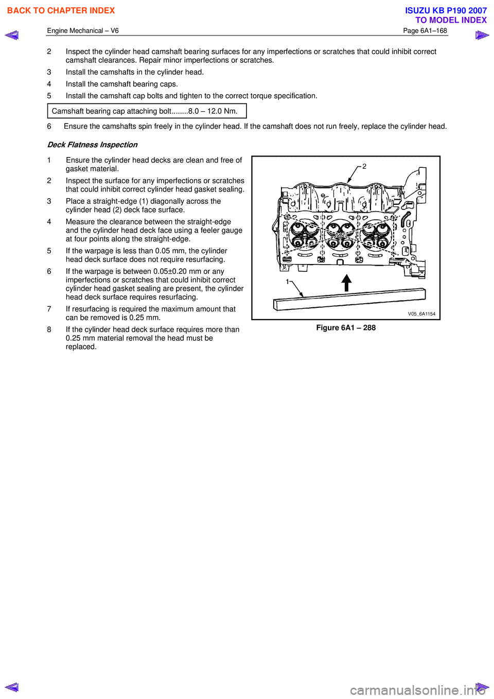
Deck Flatness Inspection
1 Ensure the cylinder head decks are clean and free of gasket material.
2 Inspect the surface for any imperfections or scratches that could inhibit correct cylinder head gasket sealing.
3 Place a straight-edge (1) diagonally across the cylinder head (2) deck face surface.
4 Measure the clearance between the straight-edge and the cylinder head deck face using a feeler gauge
at four points along the straight-edge.
5 If the warpage is less than 0.05 mm, the cylinder head deck surface does not require resurfacing.
6 If the warpage is between 0.05±0.20 mm or any imperfections or scratches that could inhibit correct
cylinder head gasket sealing are present, the cylinder
head deck surface requires resurfacing.
7 If resurfacing is required the maximum amount that can be removed is 0.25 mm.
8 If the cylinder head deck surface requires more than 0.25 mm material removal the head must be
replaced.
Figure 6A1 – 288
BACK TO CHAPTER INDEX
TO MODEL INDEX
ISUZU KB P190 2007
Page 2706 of 6020
Engine Mechanical – V6 Page 6A1–227
Crankshaft Main Bearing Inspection
CAUTION
All connecting rod and main journal bearings
that have been used in a running engine must
be replaced. Never re-use the crankshaft or
connecting rod bearings.
NOTE
The following bearing wear conditions should be
used to diagnose engine operating conditions or
root cause of a condition.
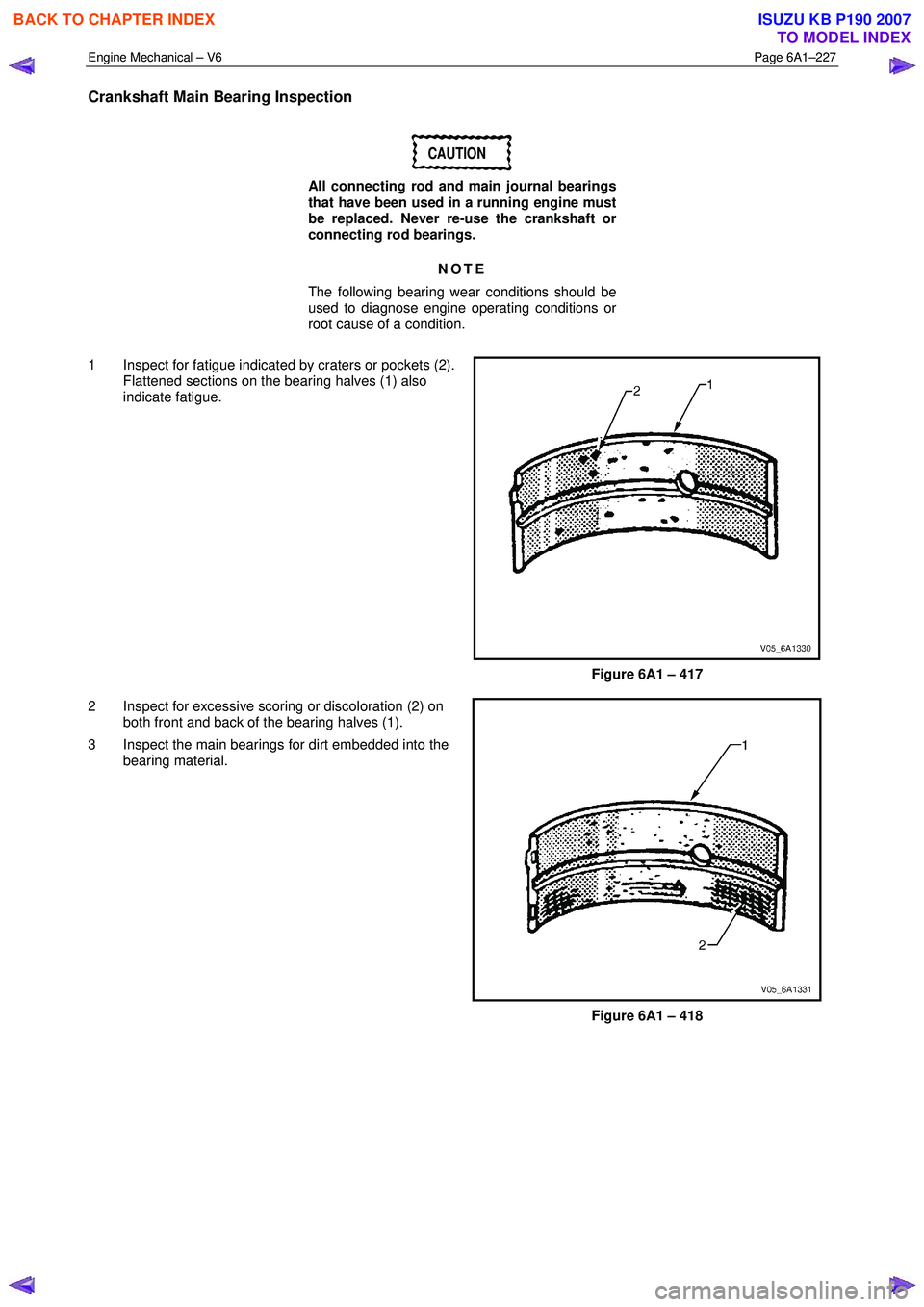
1 Inspect for fatigue indicated by craters or pockets (2). Flattened sections on the bearing halves (1) also
indicate fatigue.
Figure 6A1 – 417
2 Inspect for excessive scoring or discoloration (2) on both front and back of the bearing halves (1).
3 Inspect the main bearings for dirt embedded into the bearing material.
Figure 6A1 – 418
BACK TO CHAPTER INDEX
TO MODEL INDEX
ISUZU KB P190 2007
Page 2767 of 6020
Engine Mechanical – V6 Page 6A1–288
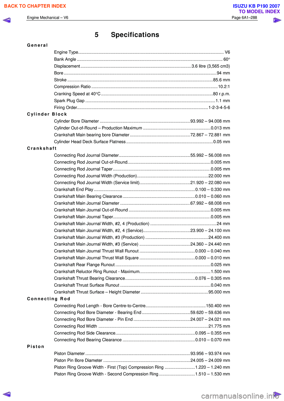
5 Specifications
General
Engine Type.................................................................................................................... ..... V6
Bank Angle ..................................................................................................................... .... 60°
Displacement ............................................................................................ 3.6 litre (3,565 cm3)
Bore ........................................................................................................................... .... 94 mm
Stroke ......................................................................................................................... 85.6 mm
Compression Ratio ......................................................................................................... 10.2: 1
Cranking Speed at 40 °C .............................................................................................80 r.p.m.
Spark Plug Gap ............................................................................................................ 1.1 m m
Firing Order............................................................................................................. 1-2-3- 4-5-6
Cylinder Block
Cylinder Bore Diameter ........................................................................... 93.992 – 94.008 mm
Cylinder Out-of-Round – Production Maximum ........................................................ 0.013 mm
Crankshaft Main bearing bore Diameter .................................................. 72.867 – 72.881 mm
Cylinder Head Deck Surface Flatness ........................................................................ 0.05 mm
Crankshaft
Connecting Rod Journal Diameter ........................................................... 55.992 – 56.008 mm
Connecting Rod Journal Out-of-Round..................................................................... 0.005 mm
Connecting Rod Journal Taper ................................................................................ .0.005 mm
Connecting Rod Journal Width (Production)........................................................... 22.000 mm
Connecting Rod Journal Width (Service limit).......................................... 21.920 – 22.080 mm
Crankshaft End Play .................................................................................... 0.100 – 0.330 mm
Crankshaft Main Bearing Clearance ............................................................ 0.010 – 0.060 mm
Crankshaft Main Journal Diameter ......................................................... .67.992 – 68.008 mm
Crankshaft Main Journal Out-of-Round .................................................................... 0.005 mm
Crankshaft Main Journal Taper................................................................................ .0.005 mm
Crankshaft Main Journal Width, #2, 4 (Production) ....................................................... 24 mm
Crankshaft Main Journal Width, #2, 4 (Service)....................................... 23.900 – 24.100 mm
Crankshaft Main Journal Width, #3 (Production) .................................................... 24.400 mm
Crankshaft Main Journal Width, #3 (Service) .......................................... 24.360 – 24.440 mm
Crankshaft Main Journal Thrust Wall Runout .............................................. 0.000 – 0.040 mm
Crankshaft Main Journal Thrust Wall Square .............................................. 0.000 – 0.010 mm
Crankshaft Rear Flange Runout ............................................................................... 0.025 mm
Crankshaft Reluctor Ring Runout - Maximum........................................................... 1.500 mm
Crankshaft Thrust Bearing Clearance.......................................................... 0.076 – 0.305 mm
Crankshaft Thrust Surface Runout ........................................................................... 0.040 mm
Crankshaft Thrust Surface – Height Diameter ........................................................ 95.000 mm
Connecting Rod
Connecting Rod Length - Bore Centre-to-Centre.................................................. 150.400 mm
Connecting Rod Bore Diameter - Bearing End ........................................ 59.620 – 59.636 mm
Connecting Rod Bore Diameter - Pin End ............................................... 24.007 – 24.021 mm
Connecting Rod Width ........................................................................................... 21.775 mm
Connecting Rod Side Clearance.................................................................. 0.095 – 0.355 mm
Connecting Rod Bearing Clearance ............................................................ 0.010 – 0.070 mm
Piston
Piston Diameter ....................................................................................... 93.956 – 93.974 mm
Piston Pin Bore Diameter ........................................................................ 24.005 – 24.009 mm
Piston Ring Groove Width - First (Top) Compression Ring ......................... 1.220 – 1.240 mm
Piston Ring Groove Width - Second Compression Ring .............................. 1.510 – 1.530 mm
BACK TO CHAPTER INDEX
TO MODEL INDEX
ISUZU KB P190 2007
Page 2768 of 6020
Engine Mechanical – V6 Page 6A1–289
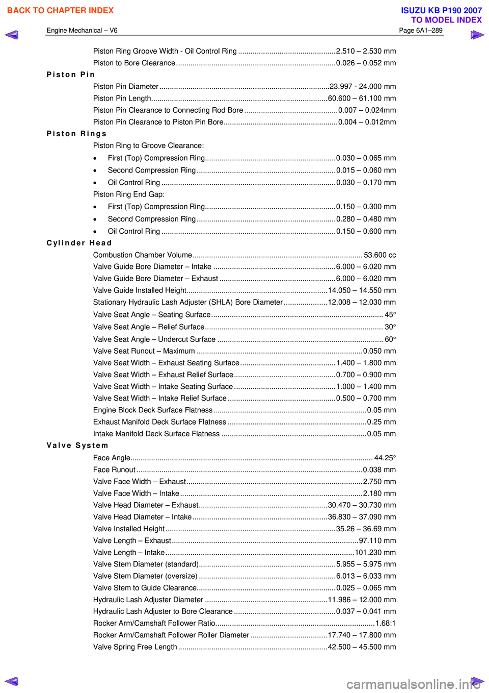
Piston Ring Groove Width - Oil Control Ring ............................................... 2.510 – 2.530 mm
Piston to Bore Clearance ............................................................................. 0.026 – 0.052 mm
Piston Pin
Piston Pin Diameter ..................................................................................23.997 - 24.000 mm
Piston Pin Length..................................................................................... 60.600 – 61.100 mm
Piston Pin Clearance to Connecting Rod Bore ............................................. 0.007 – 0.024mm
Piston Pin Clearance to Piston Pin Bore....................................................... 0.004 – 0.012mm
Piston Rings
Piston Ring to Groove Clearance:
• First (Top) Compression Ring............................................................... 0.030 – 0.065 mm
• Second Compression Ring ................................................................... 0.015 – 0.060 mm
• Oil Control Ring .................................................................................... 0.030 – 0.170 mm
Piston Ring End Gap:
• First (Top) Compression Ring............................................................... 0.150 – 0.300 mm
• Second Compression Ring ................................................................... 0.280 – 0.480 mm
• Oil Control Ring .................................................................................... 0.150 – 0.600 mm
Cylinder Head
Combustion Chamber Volume.................................................................................. 53.600 cc
Valve Guide Bore Diameter – Intake ........................................................... 6.000 – 6.020 mm
Valve Guide Bore Diameter – Exhaust ........................................................ 6.000 – 6.020 mm
Valve Guide Installed Height.................................................................... 14.050 – 14.550 mm
Stationary Hydraulic Lash Adjuster (SHLA) Bore Diameter ..................... 12.008 – 12.030 mm
Valve Seat Angle – Seating Surface ................................................................................... 45 °
Valve Seat Angle – Relief Surface ...................................................................................... 30 °
Valve Seat Angle – Undercut Surface ................................................................................ 60 °
Valve Seat Runout – Maximum ................................................................................ 0.050 mm
Valve Seat Width – Exhaust Seating Surface .............................................. 1.400 – 1.800 mm
Valve Seat Width – Exhaust Relief Surface ................................................. 0.700 – 0.900 mm
Valve Seat Width – Intake Seating Surface ................................................. 1.000 – 1.400 mm
Valve Seat Width – Intake Relief Surface .................................................... 0.500 – 0.700 mm
Engine Block Deck Surface Flatness .......................................................................... 0.05 mm
Exhaust Manifold Deck Surface Flatness ................................................................... 0.25 mm
Intake Manifold Deck Surface Flatness ...................................................................... 0.05 mm
Valve System
Face Angle..................................................................................................................... 44.25°
Face Runout ............................................................................................................. 0.038 m m
Valve Face Width – Exhaust..................................................................................... 2.750 mm
Valve Face Width – Intake ........................................................................................ 2.180 mm
Valve Head Diameter – Exhaust .............................................................. 30.470 – 30.730 mm
Valve Head Diameter – Intake ................................................................. 36.830 – 37.090 mm
Valve Installed Height .................................................................................. 35.26 – 36.69 mm
Valve Length – Exhaust .......................................................................................... 97.110 mm
Valve Length – Intake ........................................................................................... 101.230 mm
Valve Stem Diameter (standard).................................................................. 5.955 – 5.975 mm
Valve Stem Diameter (oversize) .................................................................. 6.013 – 6.033 mm
Valve Stem to Guide Clearance................................................................... 0.025 – 0.065 mm
Hydraulic Lash Adjuster Diameter ........................................................... 11.986 – 12.000 mm
Hydraulic Lash Adjuster to Bore Clearance ................................................. 0.037 – 0.041 mm
Rocker Arm/Camshaft Follower Ratio............................................................................. 1.68:1
Rocker Arm/Camshaft Follower Roller Diameter ..................................... 17.740 – 17.800 mm
Valve Spring Free Length ........................................................................ 42.500 – 45.500 mm
BACK TO CHAPTER INDEX
TO MODEL INDEX
ISUZU KB P190 2007