2007 ISUZU KB P190 run flat
[x] Cancel search: run flatPage 2825 of 6020

Engine Mechanical – V6 Page 6A1–48
Page 6A1–48
2.18 Engine Oil Leak Diagnosis
Introduction
It is important to correctly identify the source of an engine oil leak. For example, a power steering fluid leak or spillage
during servicing can travel across the va lley area of the engine and run-out the weep hole, which is located at the back of
the cylinder block. Failure to correctly identify the source of an engine oil leak can lead to unnecessary replacement of
engine components.
Most fluid leaks can be repaired by repairi ng or replacing the faulty component or resealing the gasket surface. However,
once a leak is identified it is im portant to determine and repair the c ause as well as the leak itself.
Locating and Identifying the Leak
Inspect the leaking fluid and determine whet her it is engine oil, transmission fluid, power steering fluid, brake fluid or
some other fluid. If unsure of the source of the leaking lubricant, a quick check of fluid levels should indicate where the
fluid is coming from, as one or more fluid level should be low.
Visual Inspection
Once the type of leaking fluid has been determined, a visual inspection of the affected system should be performed.
When performing the visual inspection:
1 Bring the vehicle to the normal operating temperature.
2 Park the vehicle over a large s heet of paper or other clean surface.
3 Leave the vehicle idling for 2-3 minut es, then check for dripping fluid.
4 If required, identify the type of fluid leak ing and the approximate location of the leak.
5 Visually inspect the suspected area. A small mirror may assist viewing areas that are difficult to see normally.
6 Check for leaks at all sealing surfaces and fittings.
7 Check for any cracked or damaged components.
8 If the leak cannot be located, completely clean the entire engine and surrounding components, drive the vehicle at
normal operating temperature for several k ilometres and then repeat Steps 3 to 8.
9 If the leak still cannot be located, proceed with either the Powder Method or Black Light and Dye Method as
outlined below.
Powder Method
1 Completely clean the entir e engine and surrounding components.
2 Apply an aerosol type powder (e.g. f oot powder) to the suspected area.
3 Operate the vehicle at normal operating temperature and at varying speeds for several kilometres.
4 Identify the source of the leak from the discoloration of the powder around the suspect components.
5 If required, use a small mirror to assist in vi ewing areas that are difficult to see normally.
6 Refer to Possible Causes for Engine Oil Leaks in this Section, and repair or replace components as required.
Black Light and Dye Method
A black light and die kit Tool No. J28428-E or a commercially av ailable equivalent is available to technicians to aid in
engine oil leak diagnosis. When using a black light and die kit fo r the first time, it is recommended the technician read the
manufacturers instructions prior to using the kit.
1 Add the specified amount of dye, as per manufacturers instructions, into the engine or suspected source of the oil
leak.
2 Operate the vehicle at normal operating temperature and at varying speeds for several kilometres.
3 With the vehicle parked on a flat leve l surface, aim the black light at the suspected component/s. The dyed fluid will
appear as a yellow path leading to the oil leak source
4 Refer to Possible Causes for Engine Oil Leaks in this Section, and repair or replace components as required.
BACK TO CHAPTER INDEX
TO MODEL INDEX
ISUZU KB P190 2007
Page 3000 of 6020
Engine Mechanical – V6 Page 6A1–223
Page 6A1–223
Cylinder Head Measurement
NOTE
For all cylinder head and associated component
specifications, refer to 5 Specifications.
Camshaft Journal Clearance
1 Install the camshaft bearing cap in the cylinder head without the camshaft.
2 Install the camshaft cap bolts and tight en to the correct torque specification
Camshaft bearing cap attach ing bolt........ 8.0 – 12.0 Nm.
3 Measure the camshaft bearings using an inside micrometer.
4 Subtract the camshaft journal diam eter from the camshaft bearing diameter. This will provide the running
clearance. If the running clearance exceeds specifications and the camshaft journals are within specification,
replace the cylinder head.
Camshaft Journal Alignment
1 Ensure the camshafts are serviceable, refer to 3.19 Camshaft for measuring procedures.
2 Inspect the cylinder head camshaft bearing surfaces for any imperfections or scratches that could inhibit correct
camshaft clearances. Repair minor imperfections or scratches.
3 Install the camshafts in the cylinder head.
4 Install the camshaft bearing caps.
5 Install the camshaft cap bolts and tighten to the correct torque specification.
Camshaft bearing cap attach ing bolt........ 8.0 – 12.0 Nm.
6 Ensure the camshafts spin freely in the cylinder head. If the camshaft does not run freely, replace the cylinder
head.
Deck Flatness Inspection
1 Ensure the cylinder head decks are clean and free of gasket material.
2 Inspect the surface for any imperfections or scratches
that could inhibit correct cylinder head gasket sealing.
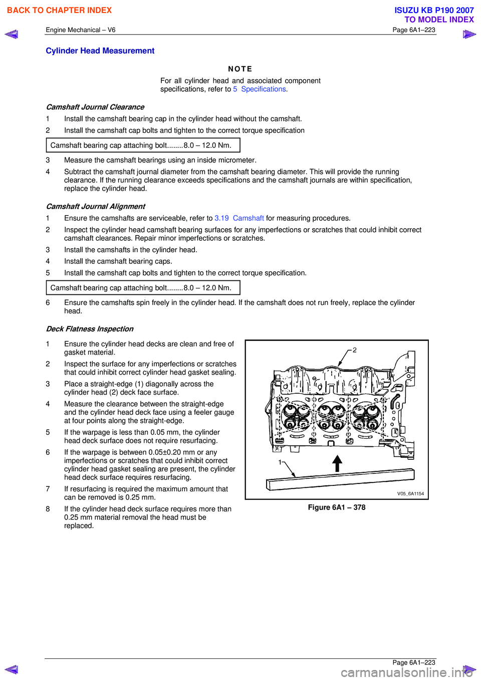
3 Place a straight-edge (1) diagonally across the cylinder head (2) deck face surface.
4 Measure the clearance between the straight-edge
and the cylinder head deck face using a feeler gauge
at four points along the straight-edge.
5 If the warpage is less t han 0.05 mm, the cylinder
head deck surface does not require resurfacing.
6 If the warpage is between 0.05±0.20 mm or any imperfections or scratches that could inhibit correct
cylinder head gasket sealing are present, the cylinder
head deck surface requires resurfacing.
7 If resurfacing is requir ed the maximum amount that
can be removed is 0.25 mm.
8 If the cylinder head deck surface requires more than 0.25 mm material removal the head must be
replaced.
Figure 6A1 – 378
BACK TO CHAPTER INDEX
TO MODEL INDEX
ISUZU KB P190 2007
Page 3062 of 6020
Engine Mechanical – V6 Page 6A1–285
Page 6A1–285
Crankshaft Main Bearing Inspection
CAUTION
All connecting rod and main journal bearings
that have been used in a running engine must
be replaced. Never re-use the crankshaft or
connecting rod bearings.
NOTE
The following bearing wear conditions should be
used to diagnose engine operating conditions or
root cause of a condition.
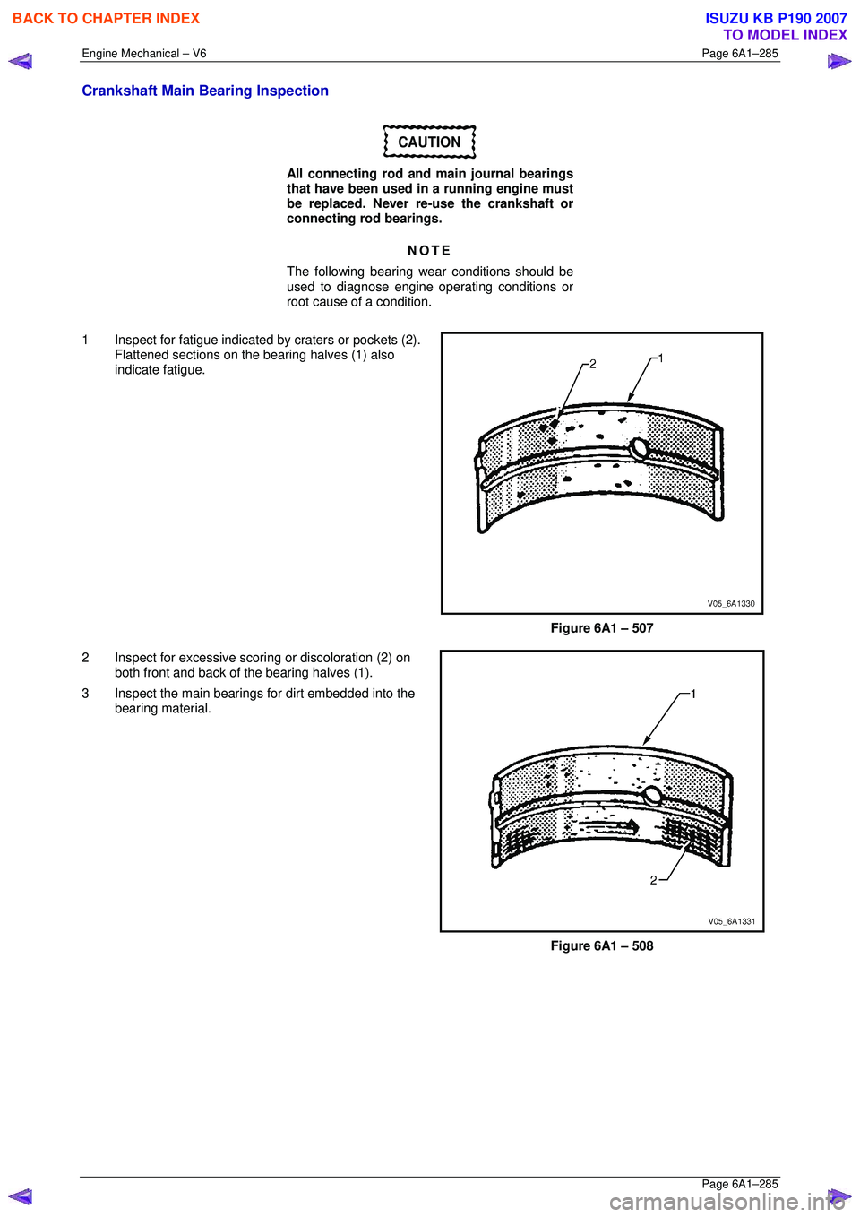
1 Inspect for fatigue indicated by craters or pockets (2). Flattened sections on the bearing halves (1) also
indicate fatigue.
Figure 6A1 – 507
2 Inspect for excessive sco ring or discoloration (2) on
both front and back of t he bearing halves (1).
3 Inspect the main bearings for dirt embedded into the bearing material.
Figure 6A1 – 508
BACK TO CHAPTER INDEX
TO MODEL INDEX
ISUZU KB P190 2007
Page 3124 of 6020
Engine Mechanical – V6 Page 6A1–347
Page 6A1–347
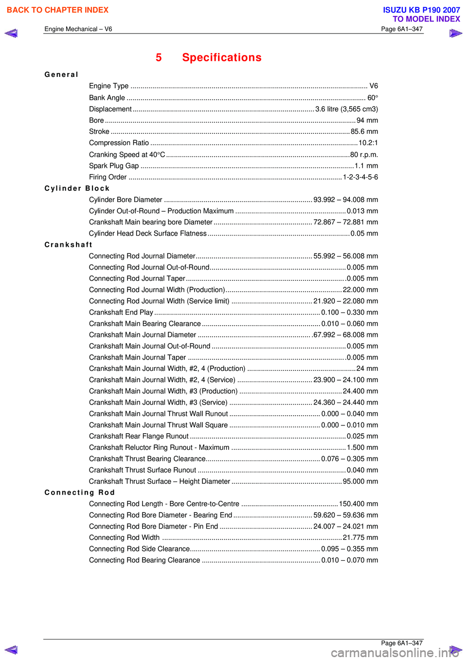
5 Specifications
General
Engine Type .................................................................................................................... .... V6
Bank An gle ..................................................................................................................... .... 60°
Displacement ............................................................................................ 3.6 litre (3,565 cm3)
Bore ........................................................................................................................... .... 94 mm
Stroke ......................................................................................................................... 85.6 mm
Compression Ratio......................................................................................................... 10. 2:1
Cranking Speed at 40 °C .............................................................................................80 r.p.m.
Spark Plug Gap ............................................................................................................ 1.1 mm
Firing Order ............................................................................................................ 1- 2-3-4-5-6
Cylinder Block
Cylinder Bore Diame ter ........................................................................... 93.992 – 94.008 mm
Cylinder Out-of-Round – Pr oduction Maximum ........................................................ 0.013 mm
Crankshaft Main bearing bor e Diameter .................................................. 72. 867 – 72.881 mm
Cylinder Head Deck Surf ace Flatness ........................................................................ 0. 05 mm
Crankshaft
Connecting Rod Journal Diameter........................................................... 55. 992 – 56.008 mm
Connecting Rod Journa l Out-of-Round..................................................................... 0.005 mm
Connecting Rod Jour nal Taper................................................................................ .0. 005 mm
Connecting Rod Journal Width (Production)........................................................... 22.000 mm
Connecting Rod Journal Width (Service limit)......................................... 21. 920 – 22.080 mm
Crankshaft End Pl ay .................................................................................... 0.100 – 0.330 mm
Crankshaft Main Bearing Clearance ............................................................ 0.010 – 0.060 mm
Crankshaft Main Journal Diameter......................................................... .67. 992 – 68.008 mm
Crankshaft Main Journa l Out-of-Round .................................................................... 0.005 mm
Crankshaft Main Journal Taper ............................................................................... .0. 005 mm
Crankshaft Main Journal Width, #2, 4 (Pr oduction)....................................................... 24 mm
Crankshaft Main Journal Width, #2, 4 (Service)...................................... 23. 900 – 24.100 mm
Crankshaft Main Journal Wi dth, #3 (Production) .................................................... 24.400 mm
Crankshaft Main Journal Width, #3 (Service).......................................... 24. 360 – 24.440 mm
Crankshaft Main Journal Thru st Wall Runout.............................................. 0.
000 – 0.040 mm
Crankshaft Main Journal Thru st Wall Square.............................................. 0. 000 – 0.010 mm
Crankshaft Rear Fl ange Runout............................................................................... 0. 025 mm
Crankshaft Reluctor Ring Ru nout - Maximum .......................................................... 1.500 mm
Crankshaft Thrust Bearin g Clearance.......................................................... 0. 076 – 0.305 mm
Crankshaft Thrust Su rface Runout........................................................................... 0. 040 mm
Crankshaft Thrust Surface – Height Diameter ........................................................ 95.000 mm
Connecting Rod
Connecting Rod Length - Bore Centre-to-Centre ................................................. 150.400 mm
Connecting Rod Bore Diameter - Bearing End........................................ 59. 620 – 59.636 mm
Connecting Rod Bore Diamet er - Pin End............................................... 24. 007 – 24.021 mm
Connecting Rod Width ........................................................................................... 21.775 mm
Connecting Rod Side Cl earance.................................................................. 0.095 – 0.355 mm
Connecting Rod Bearing Clearance ............................................................ 0.010 – 0.070 mm
BACK TO CHAPTER INDEX
TO MODEL INDEX
ISUZU KB P190 2007
Page 3125 of 6020
Engine Mechanical – V6 Page 6A1–348
Page 6A1–348
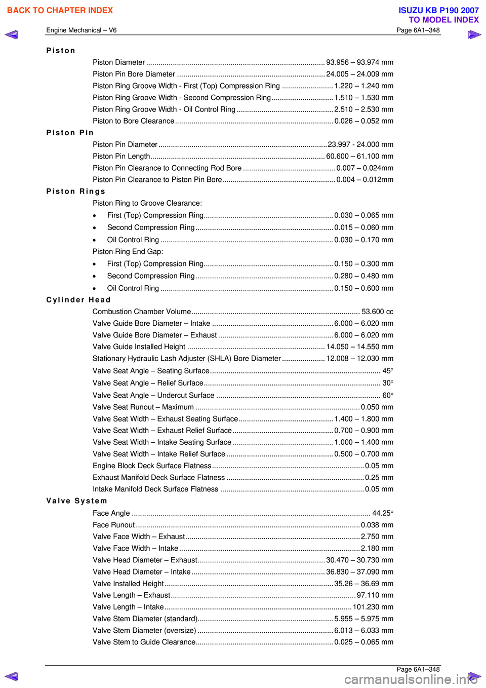
Piston
Piston Diameter ....................................................................................... 93. 956 – 93.974 mm
Piston Pin Bore Diame ter ........................................................................ 24.005 – 24.009 mm
Piston Ring Groove Width - First (Top) Compression Ring ......................... 1.220 – 1.240 mm
Piston Ring Groove Width - Second Compression Ring.............................. 1. 510 – 1.530 mm
Piston Ring Groove Width - Oil Control Ring ............................................... 2. 510 – 2.530 mm
Piston to Bore Clear ance ............................................................................. 0.026 – 0.052 mm
Piston Pin
Piston Pin Diamet er .................................................................................. 23.997 - 24.000 mm
Piston Pin Length ..................................................................................... 60. 600 – 61.100 mm
Piston Pin Clearance to Connec ting Rod Bore............................................. 0. 007 – 0.024mm
Piston Pin Clearance to Pist on Pin Bore....................................................... 0. 004 – 0.012mm
Piston Rings
Piston Ring to Groove Clearance:
• First (Top) Compression Ring............................................................... 0. 030 – 0.065 mm
• Second Compression Ring ................................................................... 0.015 – 0.060 mm
• Oil Control Ring .................................................................................... 0. 030 – 0.170 mm
Piston Ring End Gap:
• First (Top) Compression Ring............................................................... 0. 150 – 0.300 mm
• Second Compression Ring ................................................................... 0.280 – 0.480 mm
• Oil Control Ring .................................................................................... 0. 150 – 0.600 mm
Cylinder Head
Combustion Chambe r Volume.................................................................................. 53. 600 cc
Valve Guide Bore Diameter – Intake ........................................................... 6.000 – 6.020 mm
Valve Guide Bore Diameter – Exhaust ........................................................ 6.000 – 6.020 mm
Valve Guide Installed Height................................................................... 14. 050 – 14.550 mm
Stationary Hydraulic Lash Adjuster (S HLA) Bore Diameter .....................12.008 – 12.030 mm
Valve Seat Angle – Seating Surface ................................................................................... 45 °
Valve Seat Angle – Relief Surface...................................................................................... 30 °
Valve Seat Angle – Un dercut Surface ................................................................................ 60 °
Valve Seat Runout – Maximum................................................................................ 0. 050 mm
Valve Seat Width – Exhaust S eating Surface.............................................. 1. 400 – 1.800 mm
Valve Seat Width – Exhaust Re lief Surface................................................. 0. 700 – 0.900 mm
Valve Seat Width – Intake Se ating Surface................................................. 1. 000 – 1.400 mm
Valve Seat Width – Intake Relief Surface.................................................... 0. 500 – 0.700 mm
Engine Block Deck Surf ace Flatness .......................................................................... 0. 05 mm
Exhaust Manifold Deck Su rface Flatness ................................................................... 0. 25 mm
Intake Manifold Deck Su rface Flatness ...................................................................... 0. 05 mm
Valve System
Face Angle .................................................................................................................... 4 4.25°
Face Run out ............................................................................................................. 0.038 mm
Valve Face Width – Exhaust..................................................................................... 2. 750 mm
Valve Face Width – Intake........................................................................................ 2. 180 mm
Valve Head Diameter – Ex haust .............................................................. 30.470 – 30.730 mm
Valve Head Diameter – Intake ................................................................. 36. 830 – 37.090 mm
Valve Installed He ight .................................................................................. 35.26 – 36.69 mm
Valve Length – Exhaust.......................................................................................... 97. 110 mm
Valve Length – Intake ........................................................................................... 101.230 mm
Valve Stem Diameter (s tandard).................................................................. 5. 955 – 5.975 mm
Valve Stem Diameter (o versize).................................................................. 6.013 – 6.033 mm
Valve Stem to Guide Clearance................................................................... 0. 025 – 0.065 mm
BACK TO CHAPTER INDEX
TO MODEL INDEX
ISUZU KB P190 2007
Page 3778 of 6020
Automatic Transmission – 4L60E – General Information Page 7C1–18
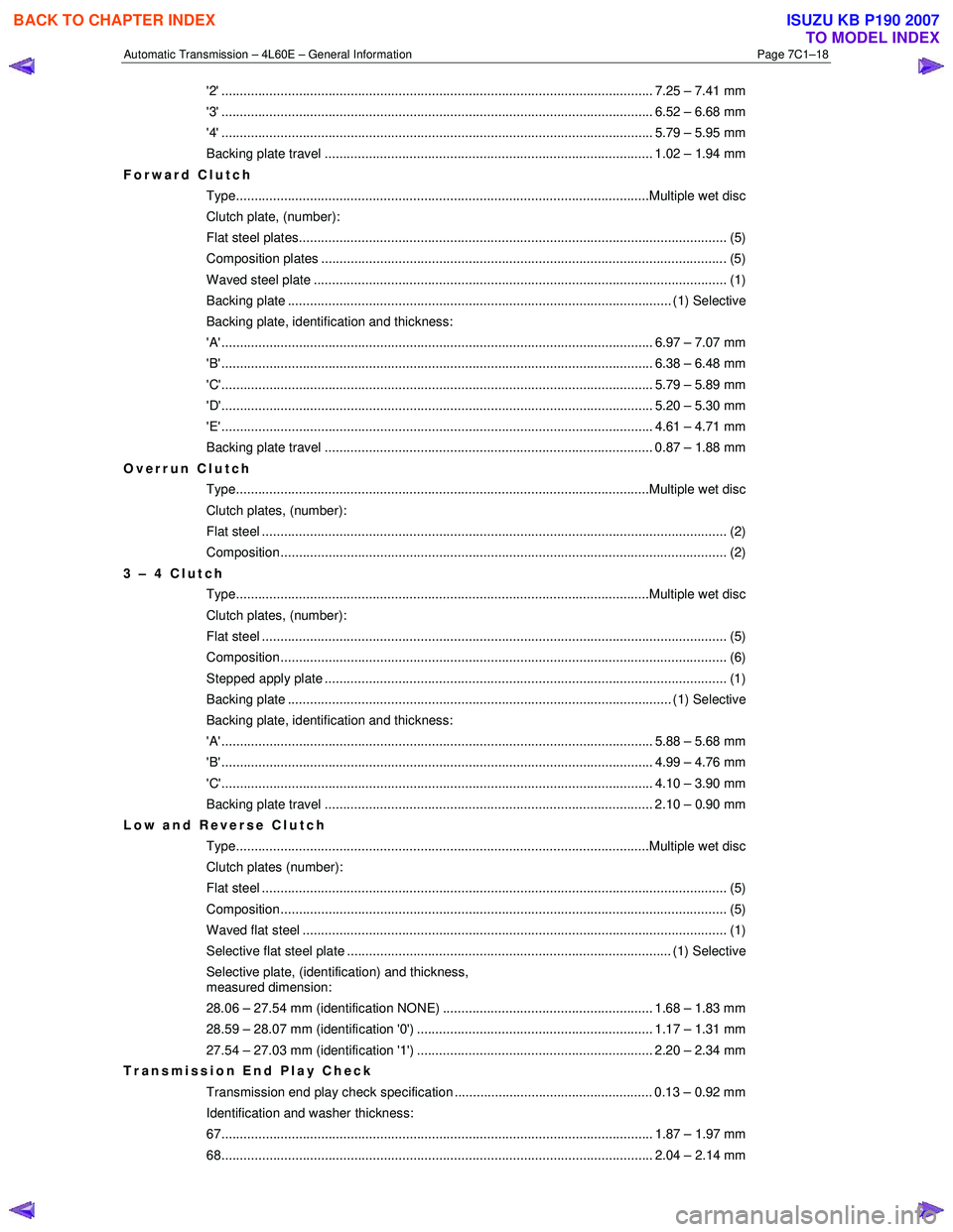
'2' ..................................................................................................................... 7.25 – 7.41 mm
'3' ..................................................................................................................... 6.52 – 6.68 mm
'4' ..................................................................................................................... 5.79 – 5.95 mm
Backing plate travel ......................................................................................... 1.02 – 1.94 mm
Forward Clutch Type................................................................................................................Multiple we t disc
Clutch plate, (number):
Flat steel plates.............................................................................................................. ...... (5)
Composition plates ............................................................................................................. .(5)
Waved steel plate .............................................................................................................. .. (1)
Backing plate ........................................................................................................ (1) Select ive
Backing plate, identification and thickness:
'A' ..................................................................................................................... 6.97 – 7.07 mm
'B' ..................................................................................................................... 6.38 – 6.48 mm
'C'..................................................................................................................... 5.79 – 5.89 mm
'D'..................................................................................................................... 5.20 – 5.30 mm
'E' ..................................................................................................................... 4.61 – 4.71 mm
Backing plate travel ......................................................................................... 0.87 – 1.88 mm
Overrun Clutch Type................................................................................................................Multiple we t disc
Clutch plates, (number):
Flat steel ..................................................................................................................... ......... (2)
Composition.................................................................................................................... ..... (2)
3 – 4 Clutch Type................................................................................................................Multiple we t disc
Clutch plates, (number):
Flat steel ..................................................................................................................... ......... (5)
Composition.................................................................................................................... ..... (6)
Stepped apply plate ............................................................................................................ .(1)
Backing plate ........................................................................................................ (1) Select ive
Backing plate, identification and thickness:
'A' ..................................................................................................................... 5.88 – 5.68 mm
'B' ..................................................................................................................... 4.99 – 4.76 mm
'C'..................................................................................................................... 4.10 – 3.90 mm
Backing plate travel ......................................................................................... 2.10 – 0.90 mm
Low and Reverse Clutch Type................................................................................................................Multiple we t disc
Clutch plates (number):
Flat steel ..................................................................................................................... ......... (5)
Composition.................................................................................................................... ..... (5)
Waved flat steel ............................................................................................................... .... (1)
Selective flat steel plate ........................................................................................ (1) Selective
Selective plate, (identification) and thickness,
measured dimension:
28.06 – 27.54 mm (identification NONE) ......................................................... 1.68 – 1.83 mm
28.59 – 28.07 mm (identification '0') ................................................................ 1.17 – 1.31 mm
27.54 – 27.03 mm (identification '1') ................................................................ 2.20 – 2.34 mm
Transmission End Play Check
Transmission end play check specification ...................................................... 0.13 – 0.92 mm
Identification and washer thickness:
67..................................................................................................................... 1.87 – 1 .97 mm
68..................................................................................................................... 2.04 – 2 .14 mm
BACK TO CHAPTER INDEX
TO MODEL INDEX
ISUZU KB P190 2007
Page 4400 of 6020
7A2-116 TRANSMISSION CONTROL SYSTEM (JR405E)
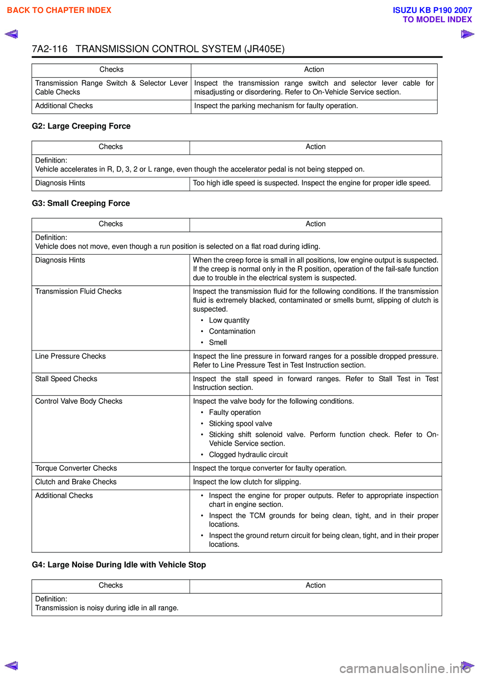
G2: Large Creeping Force
G3: Small Creeping Force
G4: Large Noise During Idle with Vehicle Stop
Transmission Range Switch & Selector Lever
Cable Checks Inspect the transmission range switch and selector lever cable for
misadjusting or disordering. Refer to On-Vehicle Service section.
Additional Checks Inspect the parking mechanism for faulty operation. Checks Action
Checks
Action
Definition:
Vehicle accelerates in R, D, 3, 2 or L range, even though the accelerator pedal is not being stepped on.
Diagnosis Hints Too high idle speed is suspected. Inspect the engine for proper idle speed.
Checks Action
Definition:
Vehicle does not move, even though a run position is selected on a flat road during idling.
Diagnosis Hints When the creep force is small in all positions, low engine output is suspected.
If the creep is normal only in the R position, operation of the fail-safe function
due to trouble in the electrical system is suspected.
Transmission Fluid Checks Inspect the transmission fluid for the following conditions. If the transmission
fluid is extremely blacked, contaminated or smells burnt, slipping of clutch is
suspected.
• Low quantity
• Contamination
•Smell
Line Pressure Checks Inspect the line pressure in forward ranges for a possible dropped pressure.
Refer to Line Pressure Test in Test Instruction section.
Stall Speed Checks Inspect the stall speed in forward ranges. Refer to Stall Test in Test
Instruction section.
Control Valve Body Checks Inspect the valve body for the following conditions.
• Faulty operation
• Sticking spool valve
• Sticking shift solenoid valve. Perform function check. Refer to On- Vehicle Service section.
• Clogged hydraulic circuit
Torque Converter Checks Inspect the torque converter for faulty operation.
Clutch and Brake Checks Inspect the low clutch for slipping.
Additional Checks • Inspect the engine for proper outputs. Refer to appropriate inspection
chart in engine section.
• Inspect the TCM grounds for being clean, tight, and in their proper locations.
• Inspect the ground return circuit for being clean, tight, and in their proper locations.
Checks Action
Definition:
Transmission is noisy during idle in all range.
BACK TO CHAPTER INDEX
TO MODEL INDEX
ISUZU KB P190 2007
Page 5651 of 6020
9A-16 SUPPLEMENTAL RESTRAINT SYSTEM
RTW 79ASH000201
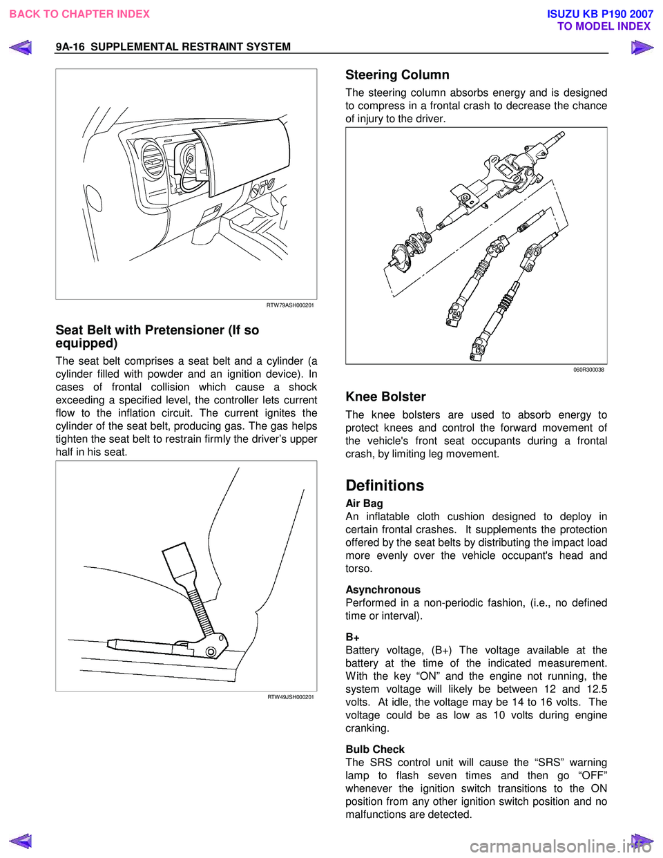
Seat Belt with Pretensioner (If so
equipped)
The seat belt comprises a seat belt and a cylinder (a
cylinder filled with powder and an ignition device). In
cases of frontal collision which cause a shock
exceeding a specified level, the controller lets current
flow to the inflation circuit. The current ignites the
cylinder of the seat belt, producing gas. The gas helps
tighten the seat belt to restrain firmly the driver’s uppe
r
half in his seat.
RTW 49JSH000201
Steering Column
The steering column absorbs energy and is designed
to compress in a frontal crash to decrease the chance
of injury to the driver.
060R300038
Knee Bolster
The knee bolsters are used to absorb energy to
protect knees and control the forward movement o
f
the vehicle's front seat occupants during a frontal
crash, by limiting leg movement.
Definitions
Air Bag
An inflatable cloth cushion designed to deploy in
certain frontal crashes. It supplements the protection
offered by the seat belts by distributing the impact load
more evenly over the vehicle occupant's head and
torso.
Asynchronous
Performed in a non-periodic fashion, (i.e., no defined
time or interval).
B+
Battery voltage, (B+) The voltage available at the
battery at the time of the indicated measurement.
W ith the key “ON” and the engine not running, the
system voltage will likely be between 12 and 12.5
volts. At idle, the voltage may be 14 to 16 volts. The
voltage could be as low as 10 volts during engine
cranking.
Bulb Check
The SRS control unit will cause the “SRS” warning
lamp to flash seven times and then go “OFF”
whenever the ignition switch transitions to the ON
position from any other ignition switch position and no
malfunctions are detected.
BACK TO CHAPTER INDEX TO MODEL INDEXISUZU KB P190 2007