2007 ISUZU KB P190 Immobilizer
[x] Cancel search: ImmobilizerPage 1097 of 6020
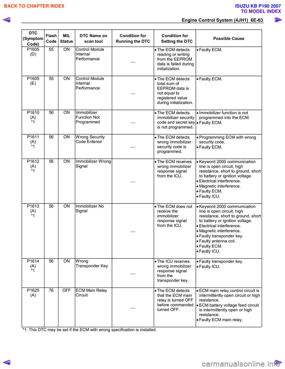
Engine Control System (4JH1) 6E-63
DTC
(Symptom Code) Flash
Code MIL
Status DTC Name on
scan tool Condition for
Running the DTC Condition for
Setting the DTC Possible Cause
P1605
(D) 55 ON Control Module
Internal
Performance •
The ECM detects
reading or writing
from the EEPROM
data is failed during
initialization.
•
Faulty ECM.
P1605
(E) 55 ON Control Module
Internal
Performance
•
The ECM detects
total sum of
EEPROM data is
not equal to
registered value
during initialization.
•
Faulty ECM.
P1610
(A) *1 56 ON Immobilizer
Function Not
Programmed •
The ECM detects
immobilizer security
code and secret key
is not programmed.
•
Immobilizer function is not
programmed into the ECM.
• Faulty ECM.
P1611 (A) *1 56 ON W rong Security
Code Entered
•
The ECM detects
wrong immobilizer
security code is
programmed.
•
Programming ECM with wrong
security code.
• Faulty ECM.
P1612 (A) *1 56 ON Immobilizer W rong
Signal
•
The ECM receives
wrong immobilizer
response signal
from the ICU.
•
Keyword 2000 communication
line is open circuit, high
resistance, short to ground, short
to battery or ignition voltage.
• Electrical interference.
• Magnetic interference.
• Faulty ECM.
• Faulty ICU.
P1613 (A) *1 56 ON Immobilizer No
Signal
•
The ECM does not
receive the
immobilizer
response signal
from the ICU.
•
Keyword 2000 communication
line is open circuit, high
resistance, short to ground, short
to battery or ignition voltage.
• Electrical interference.
• Magnetic interference.
• Faulty transponder key.
• Faulty antenna coil.
• Faulty ECM.
• Faulty ICU.
P1614 (A) *1 56 ON W rong
Transponder Key
•
The ICU receives
wrong immobilizer
response signal
from the
transponder key.
•
Faulty transponder key.
• Faulty ICU.
P1625 (A) 76 OFF ECM Main Relay
Circuit
•
The ECM detects
that the ECM main
relay is turned OFF
before commanded
turned OFF.
•
ECM main relay control circuit is
intermittently open circuit or high
resistance.
• ECM battery voltage feed circuit
is intermittently open or high
resistance.
• Faulty ECM main relay.
*1: This DTC may be set if the ECM with wrong specification is installed.
BACK TO CHAPTER INDEX
TO MODEL INDEX
ISUZU KB P190 2007
Page 1251 of 6020
Engine Control System (4JH1) 6E-217
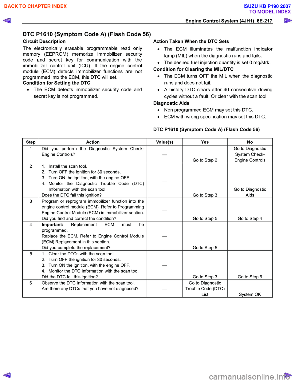
DTC P1610 (Symptom Code A) (Flash Code 56)
Circuit Description
The electronically erasable programmable read onl
y
memory (EEPROM) memorize immobilizer securit
y
code and secret key for communication with the
immobilizer control unit (ICU). If the engine control
module (ECM) detects immobilizer functions are not
programmed into the ECM, this DTC will set.
Condition for Setting the DTC
• The ECM detects immobilizer security code and
secret key is not programmed.
Action Taken When the DTC Sets
• The ECM illuminates the malfunction indicato
r
lamp (MIL) when the diagnostic runs and fails.
• The desired fuel injection quantity is set 0 mg/strk.
Condition for Clearing the MIL/DTC • The ECM turns OFF the MIL when the diagnostic
runs and does not fail.
• A history DTC clears after 40 consecutive driving
cycles without a fault. Or clear with the scan tool.
Diagnostic Aids • Non programmed ECM may set this DTC.
• ECM with wrong specification may set this DTC.
DTC P1610 (Symptom Code A) (Flash Code 56)
Step Action Value(s) Yes No
1 Did you perform the Diagnostic System Check-
Engine Controls?
Go to Step 2 Go to Diagnostic
System Check-
Engine Controls
2 1. Install the scan tool. 2. Turn OFF the ignition for 30 seconds.
3. Turn ON the ignition, with the engine OFF.
4. Monitor the Diagnostic Trouble Code (DTC) Information with the scan tool.
Does the DTC fail this ignition?
Go to Step 3 Go to Diagnostic
Aids
3 Program or reprogram immobilizer function into the engine control module (ECM). Refer to Programming
Engine Control Module (ECM) in immobilizer section.
Did you find and correct the condition?
Go to Step 5 Go to Step 4
4 Important: Replacement ECM must be
programmed.
Replace the ECM. Refer to Engine Control Module
(ECM) Replacement in this section.
Did you complete the replacement?
Go to Step 5
5 1. Clear the DTCs with the scan tool.
2. Turn OFF the ignition for 30 seconds.
3. Turn ON the ignition, with the engine OFF.
4. Monitor the DTC Information with the scan tool.
Did the DTC fail this ignition?
Go to Step 3 Go to Step 6
6 Observe the DTC Information with the scan tool. Are there any DTCs that you have not diagnosed? Go to Diagnostic
Trouble Code (DTC) List System OK
BACK TO CHAPTER INDEX
TO MODEL INDEX
ISUZU KB P190 2007
Page 1252 of 6020
6E-218 Engine Control System (4JH1)
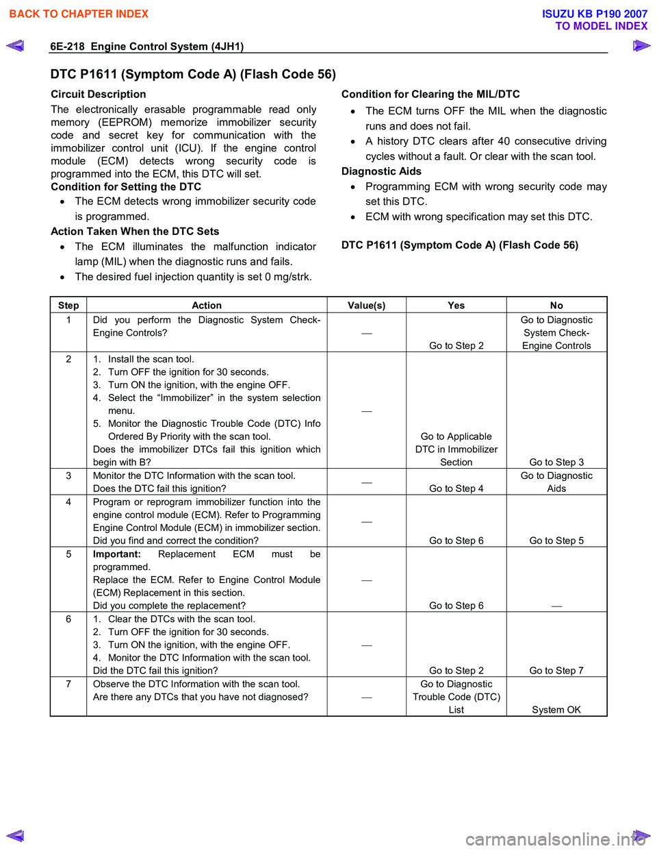
DTC P1611 (Symptom Code A) (Flash Code 56)
Circuit Description
The electronically erasable programmable read onl
y
memory (EEPROM) memorize immobilizer securit
y
code and secret key for communication with the
immobilizer control unit (ICU). If the engine control
module (ECM) detects wrong security code is
programmed into the ECM, this DTC will set.
Condition for Setting the DTC
• The ECM detects wrong immobilizer security code
is programmed.
Action Taken When the DTC Sets • The ECM illuminates the malfunction indicato
r
lamp (MIL) when the diagnostic runs and fails.
• The desired fuel injection quantity is set 0 mg/strk.
Condition for Clearing the MIL/DTC
• The ECM turns OFF the MIL when the diagnostic
runs and does not fail.
• A history DTC clears after 40 consecutive driving
cycles without a fault. Or clear with the scan tool.
Diagnostic Aids • Programming ECM with wrong security code ma
y
set this DTC.
• ECM with wrong specification may set this DTC.
DTC P1611 (Symptom Code A) (Flash Code 56)
Step Action Value(s) Yes No
1 Did you perform the Diagnostic System Check-
Engine Controls?
Go to Step 2 Go to Diagnostic
System Check-
Engine Controls
2 1. Install the scan tool. 2. Turn OFF the ignition for 30 seconds.
3. Turn ON the ignition, with the engine OFF.
4. Select the “Immobilizer” in the system selection menu.
5. Monitor the Diagnostic Trouble Code (DTC) Info Ordered By Priority with the scan tool.
Does the immobilizer DTCs fail this ignition which
begin with B?
Go to Applicable
DTC in Immobilizer Section Go to Step 3
3 Monitor the DTC Information with the scan tool. Does the DTC fail this ignition?
Go to Step 4 Go to Diagnostic
Aids
4 Program or reprogram immobilizer function into the engine control module (ECM). Refer to Programming
Engine Control Module (ECM) in immobilizer section.
Did you find and correct the condition?
Go to Step 6 Go to Step 5
5 Important: Replacement ECM must be
programmed.
Replace the ECM. Refer to Engine Control Module
(ECM) Replacement in this section.
Did you complete the replacement?
Go to Step 6
6 1. Clear the DTCs with the scan tool.
2. Turn OFF the ignition for 30 seconds.
3. Turn ON the ignition, with the engine OFF.
4. Monitor the DTC Information with the scan tool.
Did the DTC fail this ignition?
Go to Step 2 Go to Step 7
7 Observe the DTC Information with the scan tool. Are there any DTCs that you have not diagnosed? Go to Diagnostic
Trouble Code (DTC) List System OK
BACK TO CHAPTER INDEX
TO MODEL INDEX
ISUZU KB P190 2007
Page 1253 of 6020
Engine Control System (4JH1) 6E-219
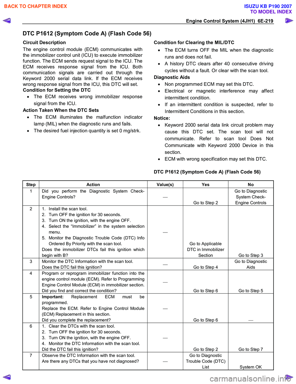
DTC P1612 (Symptom Code A) (Flash Code 56)
Circuit Description
The engine control module (ECM) communicates with
the immobilizer control unit (ICU) to execute immobilize
r
function. The ECM sends request signal to the ICU. The
ECM receives response signal from the ICU. Both
communication signals are carried out through the
Keyword 2000 serial data link. If the ECM receives
wrong response signal from the ICU, this DTC will set.
Condition for Setting the DTC
• The ECM receives wrong immobilizer response
signal from the ICU.
Action Taken When the DTC Sets • The ECM illuminates the malfunction indicato
r
lamp (MIL) when the diagnostic runs and fails.
• The desired fuel injection quantity is set 0 mg/strk.
Condition for Clearing the MIL/DTC
• The ECM turns OFF the MIL when the diagnostic
runs and does not fail.
• A history DTC clears after 40 consecutive driving
cycles without a fault. Or clear with the scan tool.
Diagnostic Aids • Non programmed ECM may set this DTC.
• Electrical or magnetic interference may affect
intermittent condition.
• If an intermittent condition is suspected, refer to
Intermittent Conditions in this section.
Notice: • Keyword 2000 serial data link circuit problem may
cause this DTC set. The scan tool will not
communicate. Refer to scan tool Does Not
Communicate with Keyword 2000 Device in this
section.
• ECM with wrong specification may set this DTC.
DTC P1612 (Symptom Code A) (Flash Code 56)
Step Action Value(s) Yes No
1 Did you perform the Diagnostic System Check-
Engine Controls?
Go to Step 2 Go to Diagnostic
System Check-
Engine Controls
2 1. Install the scan tool. 2. Turn OFF the ignition for 30 seconds.
3. Turn ON the ignition, with the engine OFF.
4. Select the “Immobilizer” in the system selection menu.
5. Monitor the Diagnostic Trouble Code (DTC) Info Ordered By Priority with the scan tool.
Does the immobilizer DTCs fail this ignition which
begin with B?
Go to Applicable
DTC in Immobilizer Section Go to Step 3
3 Monitor the DTC Information with the scan tool. Does the DTC fail this ignition?
Go to Step 4 Go to Diagnostic
Aids
4 Program or reprogram immobilizer function into the engine control module (ECM). Refer to Programming
Engine Control Module (ECM) in immobilizer section.
Did you find and correct the condition?
Go to Step 6 Go to Step 5
5 Important: Replacement ECM must be
programmed.
Replace the ECM. Refer to Engine Control Module
(ECM) Replacement in this section.
Did you complete the replacement?
Go to Step 6
6 1. Clear the DTCs with the scan tool.
2. Turn OFF the ignition for 30 seconds.
3. Turn ON the ignition, with the engine OFF.
4. Monitor the DTC Information with the scan tool.
Did the DTC fail this ignition?
Go to Step 2 Go to Step 7
7 Observe the DTC Information with the scan tool. Are there any DTCs that you have not diagnosed? Go to Diagnostic
Trouble Code (DTC) List System OK
BACK TO CHAPTER INDEX
TO MODEL INDEX
ISUZU KB P190 2007
Page 1254 of 6020
6E-220 Engine Control System (4JH1)
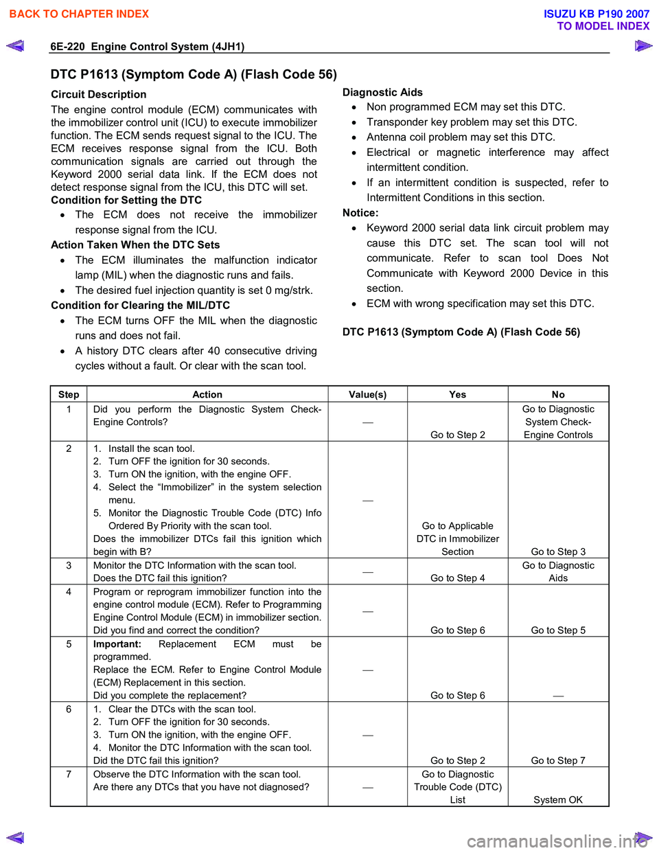
DTC P1613 (Symptom Code A) (Flash Code 56)
Circuit Description
The engine control module (ECM) communicates with
the immobilizer control unit (ICU) to execute immobilize
r
function. The ECM sends request signal to the ICU. The
ECM receives response signal from the ICU. Both
communication signals are carried out through the
Keyword 2000 serial data link. If the ECM does not
detect response signal from the ICU, this DTC will set.
Condition for Setting the DTC
• The ECM does not receive the immobilize
r
response signal from the ICU.
Action Taken When the DTC Sets • The ECM illuminates the malfunction indicato
r
lamp (MIL) when the diagnostic runs and fails.
• The desired fuel injection quantity is set 0 mg/strk.
Condition for Clearing the MIL/DTC • The ECM turns OFF the MIL when the diagnostic
runs and does not fail.
• A history DTC clears after 40 consecutive driving
cycles without a fault. Or clear with the scan tool.
Diagnostic Aids
• Non programmed ECM may set this DTC.
• Transponder key problem may set this DTC.
• Antenna coil problem may set this DTC.
• Electrical or magnetic interference may affect
intermittent condition.
• If an intermittent condition is suspected, refer to
Intermittent Conditions in this section.
Notice: • Keyword 2000 serial data link circuit problem ma
y
cause this DTC set. The scan tool will not
communicate. Refer to scan tool Does Not
Communicate with Keyword 2000 Device in this
section.
• ECM with wrong specification may set this DTC.
DTC P1613 (Symptom Code A) (Flash Code 56)
Step Action Value(s) Yes No
1 Did you perform the Diagnostic System Check-
Engine Controls?
Go to Step 2 Go to Diagnostic
System Check-
Engine Controls
2 1. Install the scan tool. 2. Turn OFF the ignition for 30 seconds.
3. Turn ON the ignition, with the engine OFF.
4. Select the “Immobilizer” in the system selection menu.
5. Monitor the Diagnostic Trouble Code (DTC) Info Ordered By Priority with the scan tool.
Does the immobilizer DTCs fail this ignition which
begin with B?
Go to Applicable
DTC in Immobilizer Section Go to Step 3
3 Monitor the DTC Information with the scan tool. Does the DTC fail this ignition?
Go to Step 4 Go to Diagnostic
Aids
4 Program or reprogram immobilizer function into the engine control module (ECM). Refer to Programming
Engine Control Module (ECM) in immobilizer section.
Did you find and correct the condition?
Go to Step 6 Go to Step 5
5 Important: Replacement ECM must be
programmed.
Replace the ECM. Refer to Engine Control Module
(ECM) Replacement in this section.
Did you complete the replacement?
Go to Step 6
6 1. Clear the DTCs with the scan tool.
2. Turn OFF the ignition for 30 seconds.
3. Turn ON the ignition, with the engine OFF.
4. Monitor the DTC Information with the scan tool.
Did the DTC fail this ignition?
Go to Step 2 Go to Step 7
7 Observe the DTC Information with the scan tool. Are there any DTCs that you have not diagnosed? Go to Diagnostic
Trouble Code (DTC) List System OK
BACK TO CHAPTER INDEX
TO MODEL INDEX
ISUZU KB P190 2007
Page 1255 of 6020
Engine Control System (4JH1) 6E-221
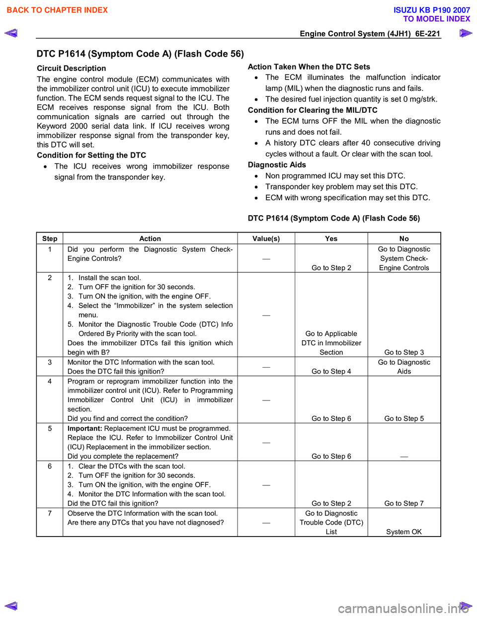
DTC P1614 (Symptom Code A) (Flash Code 56)
Circuit Description
The engine control module (ECM) communicates with
the immobilizer control unit (ICU) to execute immobilize
r
function. The ECM sends request signal to the ICU. The
ECM receives response signal from the ICU. Both
communication signals are carried out through the
Keyword 2000 serial data link. If ICU receives wrong
immobilizer response signal from the transponder key,
this DTC will set.
Condition for Setting the DTC
• The ICU receives wrong immobilizer response
signal from the transponder key.
Action Taken When the DTC Sets
• The ECM illuminates the malfunction indicato
r
lamp (MIL) when the diagnostic runs and fails.
• The desired fuel injection quantity is set 0 mg/strk.
Condition for Clearing the MIL/DTC • The ECM turns OFF the MIL when the diagnostic
runs and does not fail.
• A history DTC clears after 40 consecutive driving
cycles without a fault. Or clear with the scan tool.
Diagnostic Aids • Non programmed ICU may set this DTC.
• Transponder key problem may set this DTC.
• ECM with wrong specification may set this DTC.
DTC P1614 (Symptom Code A) (Flash Code 56)
Step Action Value(s) Yes No
1 Did you perform the Diagnostic System Check-
Engine Controls?
Go to Step 2 Go to Diagnostic
System Check-
Engine Controls
2 1. Install the scan tool. 2. Turn OFF the ignition for 30 seconds.
3. Turn ON the ignition, with the engine OFF.
4. Select the “Immobilizer” in the system selection menu.
5. Monitor the Diagnostic Trouble Code (DTC) Info Ordered By Priority with the scan tool.
Does the immobilizer DTCs fail this ignition which
begin with B?
Go to Applicable
DTC in Immobilizer Section Go to Step 3
3 Monitor the DTC Information with the scan tool. Does the DTC fail this ignition?
Go to Step 4 Go to Diagnostic
Aids
4 Program or reprogram immobilizer function into the immobilizer control unit (ICU). Refer to Programming
Immobilizer Control Unit (ICU) in immobilizer
section.
Did you find and correct the condition?
Go to Step 6 Go to Step 5
5 Important: Replacement ICU must be programmed.
Replace the ICU. Refer to Immobilizer Control Unit
(ICU) Replacement in the immobilizer section.
Did you complete the replacement?
Go to Step 6
6 1. Clear the DTCs with the scan tool.
2. Turn OFF the ignition for 30 seconds.
3. Turn ON the ignition, with the engine OFF.
4. Monitor the DTC Information with the scan tool.
Did the DTC fail this ignition?
Go to Step 2 Go to Step 7
7 Observe the DTC Information with the scan tool. Are there any DTCs that you have not diagnosed? Go to Diagnostic
Trouble Code (DTC) List System OK
BACK TO CHAPTER INDEX
TO MODEL INDEX
ISUZU KB P190 2007
Page 1623 of 6020
6E-6 ENGINE CONTROL SYSTEM (4JK1/4JJ1)
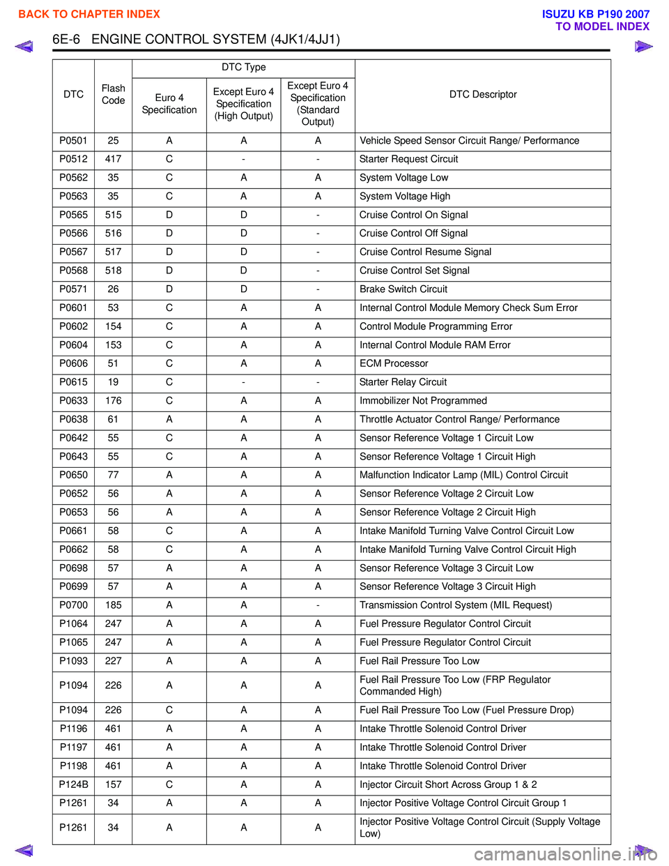
P0501 25 AAA Vehicle Speed Sensor Circuit Range/ Performance
P0512 417 C -- Starter Request Circuit
P0562 35 C AA System Voltage Low
P0563 35 C AA System Voltage High
P0565 515 D D- Cruise Control On Signal
P0566 516 D D- Cruise Control Off Signal
P0567 517 D D- Cruise Control Resume Signal
P0568 518 D D- Cruise Control Set Signal
P0571 26 D D- Brake Switch Circuit
P0601 53 C AA Internal Control Module Memory Check Sum Error
P0602 154 C AA Control Module Programming Error
P0604 153 C AA Internal Control Module RAM Error
P0606 51 C AA ECM Processor
P0615 19 C -- Starter Relay Circuit
P0633 176 C AA Immobilizer Not Programmed
P0638 61 A AA Throttle Actuator Control Range/ Performance
P0642 55 C AA Sensor Reference Voltage 1 Circuit Low
P0643 55 C AA Sensor Reference Voltage 1 Circuit High
P0650 77 A AA Malfunction Indicator Lamp (MIL) Control Circuit
P0652 56 A AA Sensor Reference Voltage 2 Circuit Low
P0653 56 A AA Sensor Reference Voltage 2 Circuit High
P0661 58 C AA Intake Manifold Turning Valve Control Circuit Low
P0662 58 C AA Intake Manifold Turning Valve Control Circuit High
P0698 57 A AA Sensor Reference Voltage 3 Circuit Low
P0699 57 A AA Sensor Reference Voltage 3 Circuit High
P0700 185 A A- Transmission Control System (MIL Request)
P1064 247 A AA Fuel Pressure Regulator Control Circuit
P1065 247 A AA Fuel Pressure Regulator Control Circuit
P1093 227 A AA Fuel Rail Pressure Too Low
P1094 226 A AAFuel Rail Pressure Too Low (FRP Regulator
Commanded High)
P1094 226 C AA Fuel Rail Pressure Too Low (Fuel Pressure Drop)
P1196 461 A AA Intake Throttle Solenoid Control Driver
P1197 461 A AA Intake Throttle Solenoid Control Driver
P1198 461 A AA Intake Throttle Solenoid Control Driver
P124B 157 C AA Injector Circuit Short Across Group 1 & 2
P1261 34 A AA Injector Positive Voltage Control Circuit Group 1
P1261 34 A AAInjector Positive Voltage Control Circuit (Supply Voltage
Low)
DTC
Flash
Code DTC Type
DTC Descriptor
Euro 4
Specification Except Euro 4
Specification
(High Output) Except Euro 4
Specification (Standard Output)
BACK TO CHAPTER INDEX
TO MODEL INDEX
ISUZU KB P190 2007
Page 1624 of 6020
ENGINE CONTROL SYSTEM (4JK1/4JJ1) 6E-7
P1261 34 CAAInjector Positive Voltage Control Circuit (Supply Voltage
High)
P1262 34 A AA Injector Positive Voltage Control Circuit Group 2
P1404 45 A AA EGR Position Fault (Closed Position Error)
P1404 45 A -- EGR Position Fault (Learned Position Error)
P1411 445 A AA EGR Solenoid Control Driver
P1412 445 A AA EGR Solenoid Control Driver
P1413 445 A AA EGR Solenoid Control Driver
P156A 135 C AA Battery Voltage Low
P156B 135 C AA Battery Voltage High
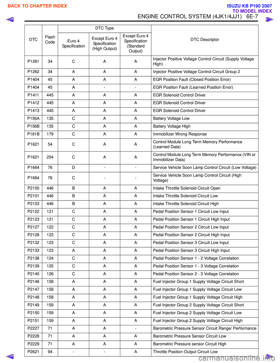
P161B 179 C AA Immobilizer Wrong Response
P1621 54 C AAControl Module Long Term Memory Performance
(Learned Data)
P1621 254 C AAControl Module Long Term Memory Performance (VIN or
Immobilizer Data)
P1664 76 D -- Service Vehicle Soon Lamp Control Circuit (Low Voltage)
P1664 76 C --Service Vehicle Soon Lamp Control Circuit (High
Voltage)
P2100 446 B AA Intake Throttle Solenoid Circuit Open
P2101 446 B AA Intake Throttle Solenoid Circuit Low
P2103 446 B AA Intake Throttle Solenoid Circuit High
P2122 121 C AA Pedal Position Sensor 1 Circuit Low Input
P2123 121 C AA Pedal Position Sensor 1 Circuit High Input
P2127 122 C AA Pedal Position Sensor 2 Circuit Low Input
P2128 122 C AA Pedal Position Sensor 2 Circuit High Input
P2132 123 C AA Pedal Position Sensor 3 Circuit Low Input
P2133 123 A AA Pedal Position Sensor 3 Circuit High Input
P2138 124 C AA Pedal Position Sensor 1 - 2 Voltage Correlation
P2139 125 C AA Pedal Position Sensor 1 - 3 Voltage Correlation
P2140 126 C AA Pedal Position Sensor 2 - 3 Voltage Correlation
P2146 158 A AA Fuel Injector Group 1 Supply Voltage Circuit Short
P2147 158 A AA Fuel Injector Group 1 Supply Voltage Circuit Low
P2148 158 A AA Fuel Injector Group 1 Supply Voltage Circuit High
P2149 159 A AA Fuel Injector Group 2 Supply Voltage Circuit Short
P2150 159 A AA Fuel Injector Group 2 Supply Voltage Circuit Low
P2151 159 A AA Fuel Injector Group 2 Supply Voltage Circuit High
P2227 71 A A- Barometric Pressure Sensor Circuit Range/ Performance
P2228 71 A AA Barometric Pressure Sensor Circuit Low
P2229 71 A AA Barometric Pressure sensor Circuit High
P2621 94 - -A Throttle Position Output Circuit Low
DTC
Flash
Code DTC Type
DTC Descriptor
Euro 4
Specification Except Euro 4
Specification
(High Output) Except Euro 4
Specification (Standard Output)
BACK TO CHAPTER INDEX
TO MODEL INDEX
ISUZU KB P190 2007