2007 ISUZU KB P190 Immobilizer
[x] Cancel search: ImmobilizerPage 1675 of 6020
6E-58 ENGINE CONTROL SYSTEM (4JK1/4JJ1)
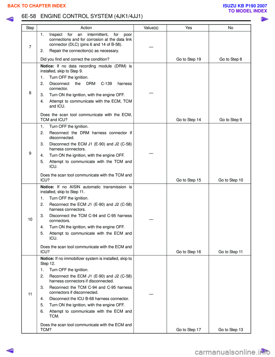
71. Inspect for an intermittent, for poor
connections and for corrosion at the data link
connector (DLC) (pins 6 and 14 of B-58).
2. Repair the connection(s) as necessary.
Did you find and correct the condition? —
Go to Step 19 Go to Step 8
8 Notice:
If no data recording module (DRM) is
installed, skip to Step 9.
1. Turn OFF the ignition.
2. Disconnect the DRM C-139 harness connector.
3. Turn ON the ignition, with the engine OFF.
4. Attempt to communicate with the ECM, TCM and ICU.
Does the scan tool communicate with the ECM,
TCM and ICU? —
Go to Step 14 Go to Step 9
9 1. Turn OFF the ignition.
2. Reconnect the DRM harness connector if disconnected.
3. Disconnect the ECM J1 (E-90) and J2 (C-58) harness connectors.
4. Turn ON the ignition, with the engine OFF.
5. Attempt to communicate with the TCM and ICU.
Does the scan tool communicate with the TCM and
ICU? —
Go to Step 15 Go to Step 10
10 Notice:
If no AISIN automatic transmission is
installed, skip to Step 11.
1. Turn OFF the ignition.
2. Reconnect the ECM J1 (E-90) and J2 (C-58) harness connectors.
3. Disconnect the TCM C-94 and C-95 harness connectors.
4. Turn ON the ignition, with the engine OFF.
5. Attempt to communicate with the ECM and ICU.
Does the scan tool communicate with the ECM and
ICU? —
Go to Step 16 Go to Step 11
11 Notice:
If no immobilizer system is installed, skip to
St ep 1 2.
1. Turn OFF the ignition.
2. Reconnect the ECM J1 (E-90) and J2 (C-58) harness connectors if disconnected.
3. Reconnect the TCM C-94 and C-95 harness connectors if disconnected.
4. Disconnect the ICU B-68 harness connector.
5. Turn ON the ignition, with the engine OFF.
6. Attempt to communicate with the ECM and TCM.
Does the scan tool communicate with the ECM and
TCM? —
Go to Step 17 Go to Step 13
Step
Action Value(s)Yes No
BACK TO CHAPTER INDEX
TO MODEL INDEX
ISUZU KB P190 2007
Page 1677 of 6020
6E-60 ENGINE CONTROL SYSTEM (4JK1/4JJ1)
Lost Communication with The Engine Control Module (ECM)
Circuit Description
The ECM, transmission control module (TCM) (AISIN
A/T only) and immobilizer control unit (ICU) all
communicate with the scan tool over the controller area
network (CAN) link. The ECM, TCM, ICU and the data
recording module (DRM) communicate with each other
over the same CAN link. If no immobilizer system is
installed, the instrument panel (IP) cluster has a CAN
terminating resistor instead of the ICU. Schematic Reference:
Engine Controls Schematics
Connector End View Reference: Engine Controls
Connector End Views or ECM Connector End Views
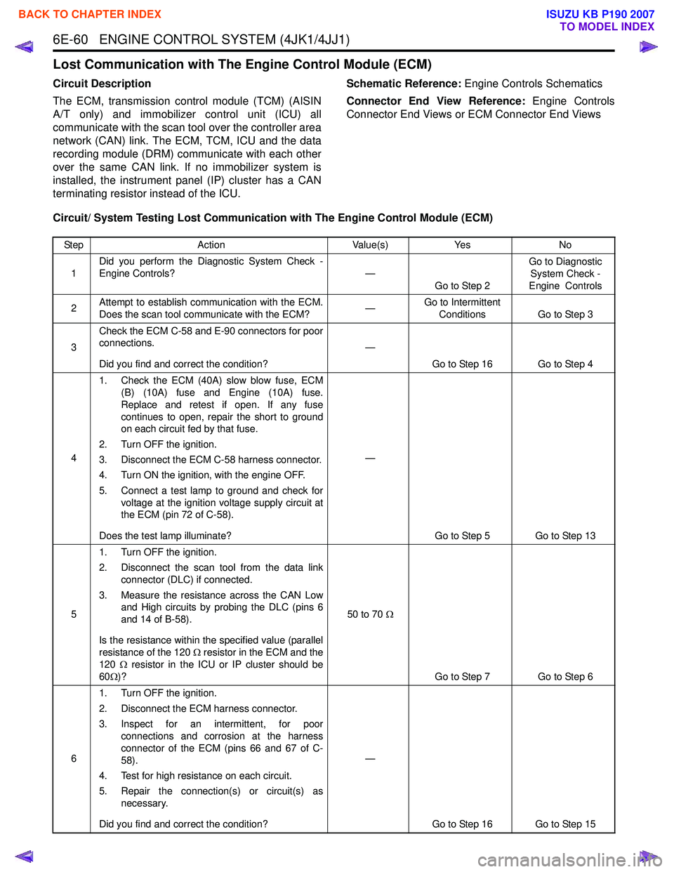
Circuit/ System Testing Lost Communication with The Engine Control Module (ECM)
Step Action Value(s)Yes No
1 Did you perform the Diagnostic System Check -
Engine Controls? —
Go to Step 2 Go to Diagnostic
System Check -
Engine Controls
2 Attempt to establish communication with the ECM.
Does the scan tool communicate with the ECM? —Go to Intermittent
Conditions Go to Step 3
3 Check the ECM C-58 and E-90 connectors for poor
connections.
Did you find and correct the condition? —
Go to Step 16 Go to Step 4
4 1. Check the ECM (40A) slow blow fuse, ECM
(B) (10A) fuse and Engine (10A) fuse.
Replace and retest if open. If any fuse
continues to open, repair the short to ground
on each circuit fed by that fuse.
2. Turn OFF the ignition.
3. Disconnect the ECM C-58 harness connector.
4. Turn ON the ignition, with the engine OFF.
5. Connect a test lamp to ground and check for voltage at the ignition voltage supply circuit at
the ECM (pin 72 of C-58).
Does the test lamp illuminate? —
Go to Step 5 Go to Step 13
5 1. Turn OFF the ignition.
2. Disconnect the scan tool from the data link connector (DLC) if connected.
3. Measure the resistance across the CAN Low and High circuits by probing the DLC (pins 6
and 14 of B-58).
Is the resistance within the specified value (parallel
resistance of the 120 Ω resistor in the ECM and the
120 Ω resistor in the ICU or IP cluster should be
60 Ω)? 50 to 70
Ω
Go to Step 7 Go to Step 6
6 1. Turn OFF the ignition.
2. Disconnect the ECM harness connector.
3. Inspect for an intermittent, for poor connections and corrosion at the harness
connector of the ECM (pins 66 and 67 of C-
58).
4. Test for high resistance on each circuit.
5. Repair the connection(s) or circuit(s) as necessary.
Did you find and correct the condition? —
Go to Step 16 Go to Step 15
BACK TO CHAPTER INDEX
TO MODEL INDEX
ISUZU KB P190 2007
Page 1815 of 6020
6E-198 ENGINE CONTROL SYSTEM (4JK1/4JJ1)
DTC P0615 (Flash Code 19)
Circuit Description
The ECM controls the starter cut relay, which de-
energizes the starter relay based on engine speed
inputs or immobilizer command signal. The starter cut
relay uses normally close type relay. During engine
stopping, the starter cut relay is closed to allow
grounding the starter relay. Once engine run, the ECM
energizes the starter cut relay to open the starter relay
circuit and starter motor is disengaged even the ignition
is positioned at START. If the ECM detects an improper
voltage on the starter cut relay control circuit, this DTC
will set.
Condition for Running the DTC • The ignition switch is ON.
Condition for Setting the DTC
Either of following condition is met: • The ECM detects a short to ground circuit condition on the starter cut relay control circuit for
longer than 3 seconds when the relay is
commanded OFF. • The ECM detects a short to voltage circuit
condition on the starter cut relay control circuit for
longer than 3 seconds when the relay is
commanded ON.
Action Taken When the DTC Sets • The ECM illuminates the SVS lamp when the diagnostic runs and fails. Refer to DTC Type
Definitions for Action Taken When the DTC Sets -
Typ e C.
Condition for Clearing the DTC • Refer to DTC Type Definitions for Condition for Clearing the SVS Lamp/ DTC - Type C.
Diagnostic Aids • If an intermittent condition is suspected, refer to Intermittent Conditions in this section.
Notice: • If the starter cut relay control circuit is short to ground, engine does not crank.
Schematic Reference: Engine Controls Schematics
Connector End View Reference: Engine Controls
Connector End Views or ECM Connector End Views
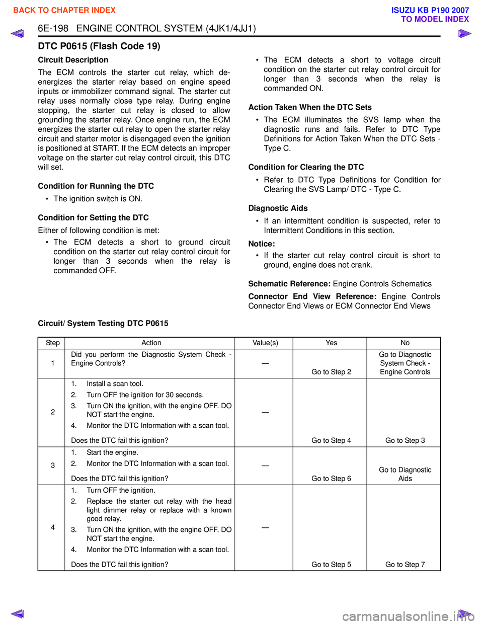
Circuit/ System Testing DTC P0615
Step Action Value(s)Yes No
1 Did you perform the Diagnostic System Check -
Engine Controls? —
Go to Step 2 Go to Diagnostic
System Check -
Engine Controls
2 1. Install a scan tool.
2. Turn OFF the ignition for 30 seconds.
3. Turn ON the ignition, with the engine OFF. DO NOT start the engine.
4. Monitor the DTC Information with a scan tool.
Does the DTC fail this ignition? —
Go to Step 4 Go to Step 3
3 1. Start the engine.
2. Monitor the DTC Information with a scan tool.
Does the DTC fail this ignition? —
Go to Step 6 Go to Diagnostic
Aids
4 1. Turn OFF the ignition.
2. Replace the starter cut relay with the head light dimmer relay or replace with a known
good relay.
3. Turn ON the ignition, with the engine OFF. DO NOT start the engine.
4. Monitor the DTC Information with a scan tool.
Does the DTC fail this ignition? —
Go to Step 5 Go to Step 7
BACK TO CHAPTER INDEX
TO MODEL INDEX
ISUZU KB P190 2007
Page 1817 of 6020
6E-200 ENGINE CONTROL SYSTEM (4JK1/4JJ1)
DTC P0633 (Flash Code 176)
Circuit Description
The electronically erasable & programmable read only
memory (EEPROM) memorizes immobilizer security
information for communication with the immobilizer
control unit (ICU) and enabling the engine to start. If the
ECM detects immobilizer security information are not
programmed into the ECM, this DTC will set.
Condition for Setting the DTC • The ECM detects that the immobilizer security information is not programmed.
Action Taken When the DTC Sets • The ECM illuminates the SVS lamp when the diagnostic runs and fails. Refer to DTC Type
Definitions for Action Taken When the DTC Sets -
Type C. (Euro 4 Specification) • The ECM illuminates the MIL when the diagnostic
runs and fails. Refer to DTC Type Definitions for
Action Taken When the DTC Sets - Type A.
(Except Euro 4 Specification)
Condition for Clearing the DTC • Refer to DTC Type Definitions for Condition for Clearing the SVS Lamp/ DTC - Type C. (Euro 4
Specification)
• Refer to DTC Type Definitions for Condition for Clearing the MIL/ DTC - Type A. (Except Euro 4
Specification)
Diagnostic Aids • Non-programmed ECM sets this DTC.
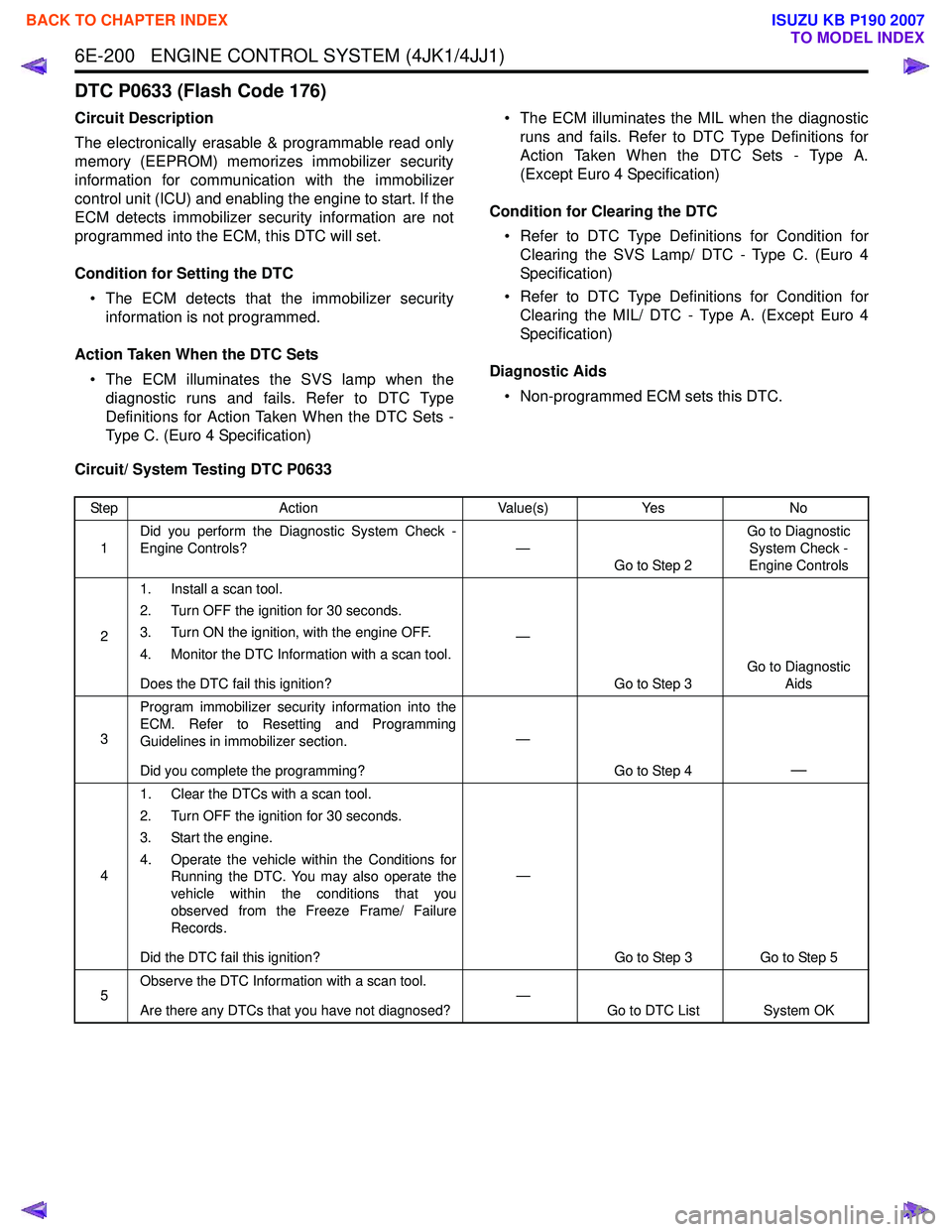
Circuit/ System Testing DTC P0633
Step Action Value(s)Yes No
1 Did you perform the Diagnostic System Check -
Engine Controls? —
Go to Step 2 Go to Diagnostic
System Check -
Engine Controls
2 1. Install a scan tool.
2. Turn OFF the ignition for 30 seconds.
3. Turn ON the ignition, with the engine OFF.
4. Monitor the DTC Information with a scan tool.
Does the DTC fail this ignition? —
Go to Step 3 Go to Diagnostic
Aids
3 Program immobilizer security information into the
ECM. Refer to Resetting and Programming
Guidelines in immobilizer section.
Did you complete the programming? —
Go to Step 4
—
41. Clear the DTCs with a scan tool.
2. Turn OFF the ignition for 30 seconds.
3. Start the engine.
4. Operate the vehicle within the Conditions for Running the DTC. You may also operate the
vehicle within the conditions that you
observed from the Freeze Frame/ Failure
Records.
Did the DTC fail this ignition? —
Go to Step 3 Go to Step 5
5 Observe the DTC Information with a scan tool.
Are there any DTCs that you have not diagnosed? —
Go to DTC List System OK
BACK TO CHAPTER INDEX
TO MODEL INDEX
ISUZU KB P190 2007
Page 1870 of 6020
ENGINE CONTROL SYSTEM (4JK1/4JJ1) 6E-253
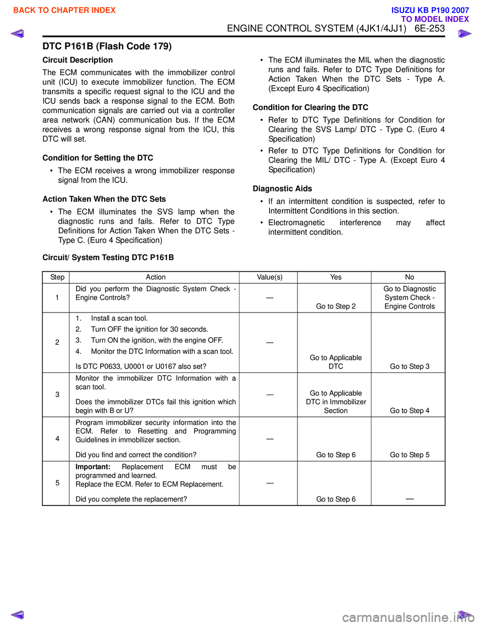
DTC P161B (Flash Code 179)
Circuit Description
The ECM communicates with the immobilizer control
unit (ICU) to execute immobilizer function. The ECM
transmits a specific request signal to the ICU and the
ICU sends back a response signal to the ECM. Both
communication signals are carried out via a controller
area network (CAN) communication bus. If the ECM
receives a wrong response signal from the ICU, this
DTC will set.
Condition for Setting the DTC • The ECM receives a wrong immobilizer response signal from the ICU.
Action Taken When the DTC Sets • The ECM illuminates the SVS lamp when the diagnostic runs and fails. Refer to DTC Type
Definitions for Action Taken When the DTC Sets -
Type C. (Euro 4 Specification) • The ECM illuminates the MIL when the diagnostic
runs and fails. Refer to DTC Type Definitions for
Action Taken When the DTC Sets - Type A.
(Except Euro 4 Specification)
Condition for Clearing the DTC • Refer to DTC Type Definitions for Condition for Clearing the SVS Lamp/ DTC - Type C. (Euro 4
Specification)
• Refer to DTC Type Definitions for Condition for Clearing the MIL/ DTC - Type A. (Except Euro 4
Specification)
Diagnostic Aids • If an intermittent condition is suspected, refer to Intermittent Conditions in this section.
• Electromagnetic interference may affect intermittent condition.
Circuit/ System Testing DTC P161B
Step Action Value(s)Yes No
1 Did you perform the Diagnostic System Check -
Engine Controls? —
Go to Step 2 Go to Diagnostic
System Check -
Engine Controls
2 1. Install a scan tool.
2. Turn OFF the ignition for 30 seconds.
3. Turn ON the ignition, with the engine OFF.
4. Monitor the DTC Information with a scan tool.
Is DTC P0633, U0001 or U0167 also set? —
Go to Applicable DTC Go to Step 3
3 Monitor the immobilizer DTC Information with a
scan tool.
Does the immobilizer DTCs fail this ignition which
begin with B or U? —
Go to Applicable
DTC in Immobilizer Section Go to Step 4
4 Program immobilizer security information into the
ECM. Refer to Resetting and Programming
Guidelines in immobilizer section.
Did you find and correct the condition? —
Go to Step 6 Go to Step 5
5 Important:
Replacement ECM must be
programmed and learned.
Replace the ECM. Refer to ECM Replacement.
Did you complete the replacement? —
Go to Step 6
—
BACK TO CHAPTER INDEX
TO MODEL INDEX
ISUZU KB P190 2007
Page 1872 of 6020
ENGINE CONTROL SYSTEM (4JK1/4JJ1) 6E-255
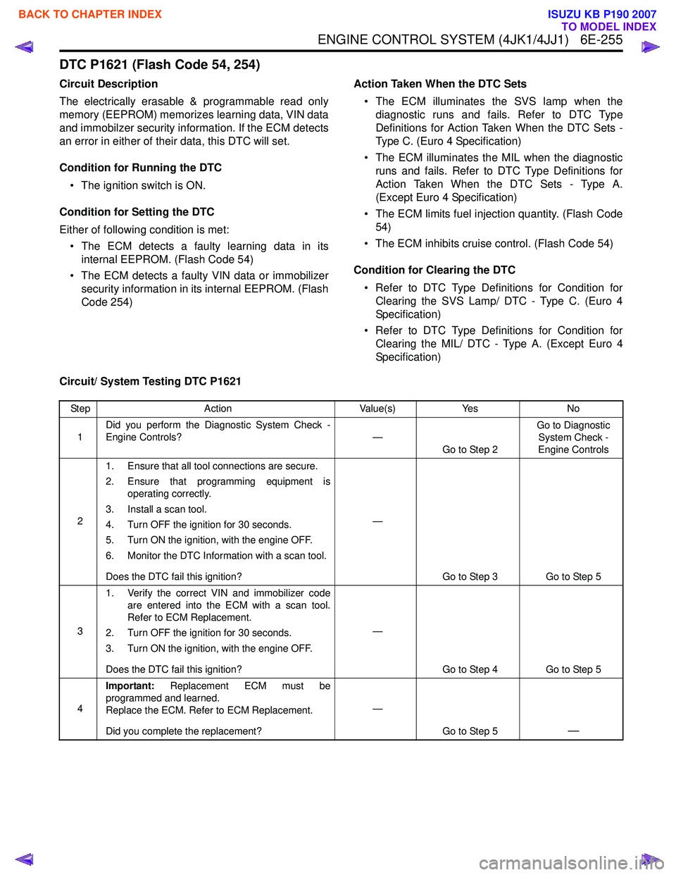
DTC P1621 (Flash Code 54, 254)
Circuit Description
The electrically erasable & programmable read only
memory (EEPROM) memorizes learning data, VIN data
and immobilzer security information. If the ECM detects
an error in either of their data, this DTC will set.
Condition for Running the DTC • The ignition switch is ON.
Condition for Setting the DTC
Either of following condition is met: • The ECM detects a faulty learning data in its internal EEPROM. (Flash Code 54)
• The ECM detects a faulty VIN data or immobilizer security information in its internal EEPROM. (Flash
Code 254) Action Taken When the DTC Sets
• The ECM illuminates the SVS lamp when the diagnostic runs and fails. Refer to DTC Type
Definitions for Action Taken When the DTC Sets -
Type C. (Euro 4 Specification)
• The ECM illuminates the MIL when the diagnostic runs and fails. Refer to DTC Type Definitions for
Action Taken When the DTC Sets - Type A.
(Except Euro 4 Specification)
• The ECM limits fuel injection quantity. (Flash Code 54)
• The ECM inhibits cruise control. (Flash Code 54)
Condition for Clearing the DTC • Refer to DTC Type Definitions for Condition for Clearing the SVS Lamp/ DTC - Type C. (Euro 4
Specification)
• Refer to DTC Type Definitions for Condition for Clearing the MIL/ DTC - Type A. (Except Euro 4
Specification)
Circuit/ System Testing DTC P1621
Step Action Value(s)Yes No
1 Did you perform the Diagnostic System Check -
Engine Controls? —
Go to Step 2 Go to Diagnostic
System Check -
Engine Controls
2 1. Ensure that all tool connections are secure.
2. Ensure that programming equipment is operating correctly.
3. Install a scan tool.
4. Turn OFF the ignition for 30 seconds.
5. Turn ON the ignition, with the engine OFF.
6. Monitor the DTC Information with a scan tool.
Does the DTC fail this ignition? —
Go to Step 3 Go to Step 5
3 1. Verify the correct VIN and immobilizer code
are entered into the ECM with a scan tool.
Refer to ECM Replacement.
2. Turn OFF the ignition for 30 seconds.
3. Turn ON the ignition, with the engine OFF.
Does the DTC fail this ignition? —
Go to Step 4 Go to Step 5
4 Important:
Replacement ECM must be
programmed and learned.
Replace the ECM. Refer to ECM Replacement.
Did you complete the replacement? —
Go to Step 5
—
BACK TO CHAPTER INDEX
TO MODEL INDEX
ISUZU KB P190 2007
Page 1917 of 6020
6E-300 ENGINE CONTROL SYSTEM (4JK1/4JJ1)
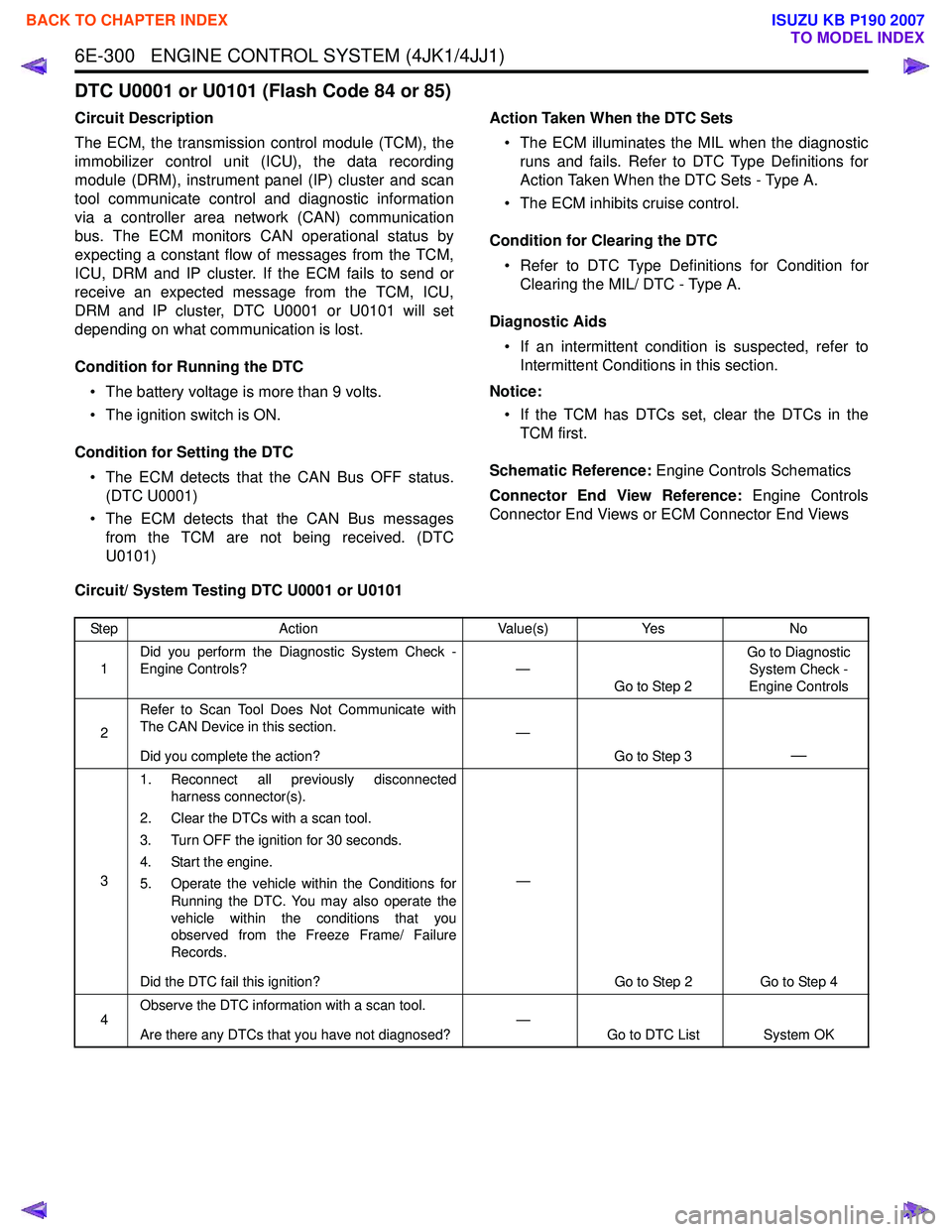
DTC U0001 or U0101 (Flash Code 84 or 85)
Circuit Description
The ECM, the transmission control module (TCM), the
immobilizer control unit (ICU), the data recording
module (DRM), instrument panel (IP) cluster and scan
tool communicate control and diagnostic information
via a controller area network (CAN) communication
bus. The ECM monitors CAN operational status by
expecting a constant flow of messages from the TCM,
ICU, DRM and IP cluster. If the ECM fails to send or
receive an expected message from the TCM, ICU,
DRM and IP cluster, DTC U0001 or U0101 will set
depending on what communication is lost.
Condition for Running the DTC • The battery voltage is more than 9 volts.
• The ignition switch is ON.
Condition for Setting the DTC • The ECM detects that the CAN Bus OFF status. (DTC U0001)
• The ECM detects that the CAN Bus messages from the TCM are not being received. (DTC
U0101) Action Taken When the DTC Sets
• The ECM illuminates the MIL when the diagnostic runs and fails. Refer to DTC Type Definitions for
Action Taken When the DTC Sets - Type A.
• The ECM inhibits cruise control.
Condition for Clearing the DTC • Refer to DTC Type Definitions for Condition for Clearing the MIL/ DTC - Type A.
Diagnostic Aids • If an intermittent condition is suspected, refer to Intermittent Conditions in this section.
Notice: • If the TCM has DTCs set, clear the DTCs in the TCM first.
Schematic Reference: Engine Controls Schematics
Connector End View Reference: Engine Controls
Connector End Views or ECM Connector End Views
Circuit/ System Testing DTC U0001 or U0101
Step Action Value(s)Yes No
1 Did you perform the Diagnostic System Check -
Engine Controls? —
Go to Step 2 Go to Diagnostic
System Check -
Engine Controls
2 Refer to Scan Tool Does Not Communicate with
The CAN Device in this section.
Did you complete the action? —
Go to Step 3
—
31. Reconnect all previously disconnected
harness connector(s).
2. Clear the DTCs with a scan tool.
3. Turn OFF the ignition for 30 seconds.
4. Start the engine.
5. Operate the vehicle within the Conditions for Running the DTC. You may also operate the
vehicle within the conditions that you
observed from the Freeze Frame/ Failure
Records.
Did the DTC fail this ignition? —
Go to Step 2 Go to Step 4
4 Observe the DTC information with a scan tool.
Are there any DTCs that you have not diagnosed? —
Go to DTC List System OK
BACK TO CHAPTER INDEX
TO MODEL INDEX
ISUZU KB P190 2007
Page 1918 of 6020
ENGINE CONTROL SYSTEM (4JK1/4JJ1) 6E-301
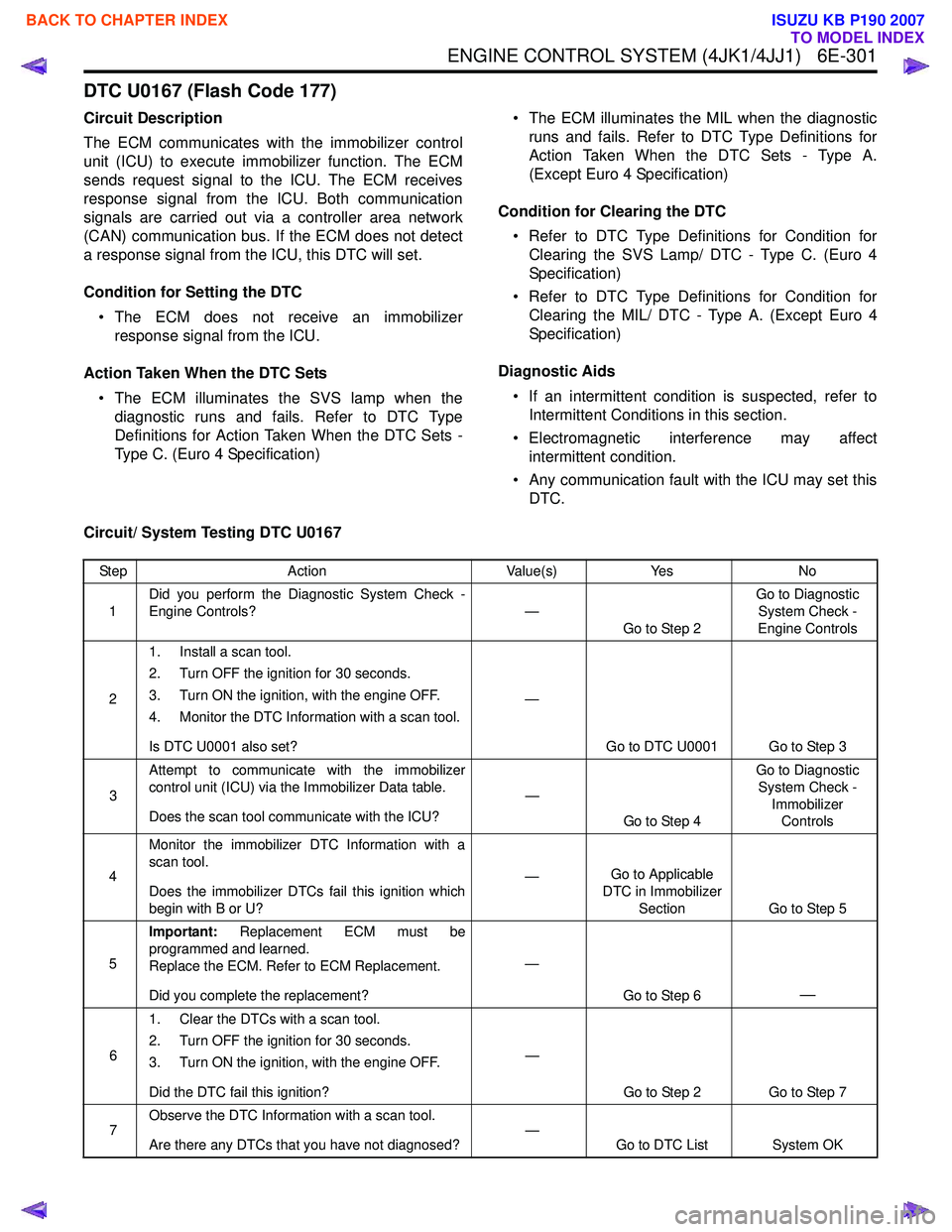
DTC U0167 (Flash Code 177)
Circuit Description
The ECM communicates with the immobilizer control
unit (ICU) to execute immobilizer function. The ECM
sends request signal to the ICU. The ECM receives
response signal from the ICU. Both communication
signals are carried out via a controller area network
(CAN) communication bus. If the ECM does not detect
a response signal from the ICU, this DTC will set.
Condition for Setting the DTC • The ECM does not receive an immobilizer response signal from the ICU.
Action Taken When the DTC Sets • The ECM illuminates the SVS lamp when the diagnostic runs and fails. Refer to DTC Type
Definitions for Action Taken When the DTC Sets -
Type C. (Euro 4 Specification) • The ECM illuminates the MIL when the diagnostic
runs and fails. Refer to DTC Type Definitions for
Action Taken When the DTC Sets - Type A.
(Except Euro 4 Specification)
Condition for Clearing the DTC • Refer to DTC Type Definitions for Condition for Clearing the SVS Lamp/ DTC - Type C. (Euro 4
Specification)
• Refer to DTC Type Definitions for Condition for Clearing the MIL/ DTC - Type A. (Except Euro 4
Specification)
Diagnostic Aids • If an intermittent condition is suspected, refer to Intermittent Conditions in this section.
• Electromagnetic interference may affect intermittent condition.
• Any communication fault with the ICU may set this DTC.
Circuit/ System Testing DTC U0167
Step Action Value(s)Yes No
1 Did you perform the Diagnostic System Check -
Engine Controls? —
Go to Step 2 Go to Diagnostic
System Check -
Engine Controls
2 1. Install a scan tool.
2. Turn OFF the ignition for 30 seconds.
3. Turn ON the ignition, with the engine OFF.
4. Monitor the DTC Information with a scan tool.
Is DTC U0001 also set? —
Go to DTC U0001 Go to Step 3
3 Attempt to communicate with the immobilizer
control unit (ICU) via the Immobilizer Data table.
Does the scan tool communicate with the ICU? —
Go to Step 4 Go to Diagnostic
System Check - Immobilizer Controls
4 Monitor the immobilizer DTC Information with a
scan tool.
Does the immobilizer DTCs fail this ignition which
begin with B or U? —
Go to Applicable
DTC in Immobilizer
Section Go to Step 5
5 Important:
Replacement ECM must be
programmed and learned.
Replace the ECM. Refer to ECM Replacement.
Did you complete the replacement? —
Go to Step 6
—
61. Clear the DTCs with a scan tool.
2. Turn OFF the ignition for 30 seconds.
3. Turn ON the ignition, with the engine OFF.
Did the DTC fail this ignition? —
Go to Step 2 Go to Step 7
7 Observe the DTC Information with a scan tool.
Are there any DTCs that you have not diagnosed? —
Go to DTC List System OK
BACK TO CHAPTER INDEX
TO MODEL INDEX
ISUZU KB P190 2007