Page 2263 of 6020
ENGINE DRIVEABILITY AND EMISSIONS 6E–93
13 Replace the ECM. Is the action complete?
IMPORTANT: The replacement ECM must be
programmed. Refer to section of the Service
Programming System (SPS) in this manual.
Following ECM programming, the immobilizer system
(if equipped) must be linked to the ECM. Refer to
section 11 “Immobilizer System-ECM replacement” for
the ECM/Immobilizer linking procedure. — Verify repair —
Step
Action Value(s) Yes No
BACK TO CHAPTER INDEX
TO MODEL INDEX
ISUZU KB P190 2007
Page 2265 of 6020

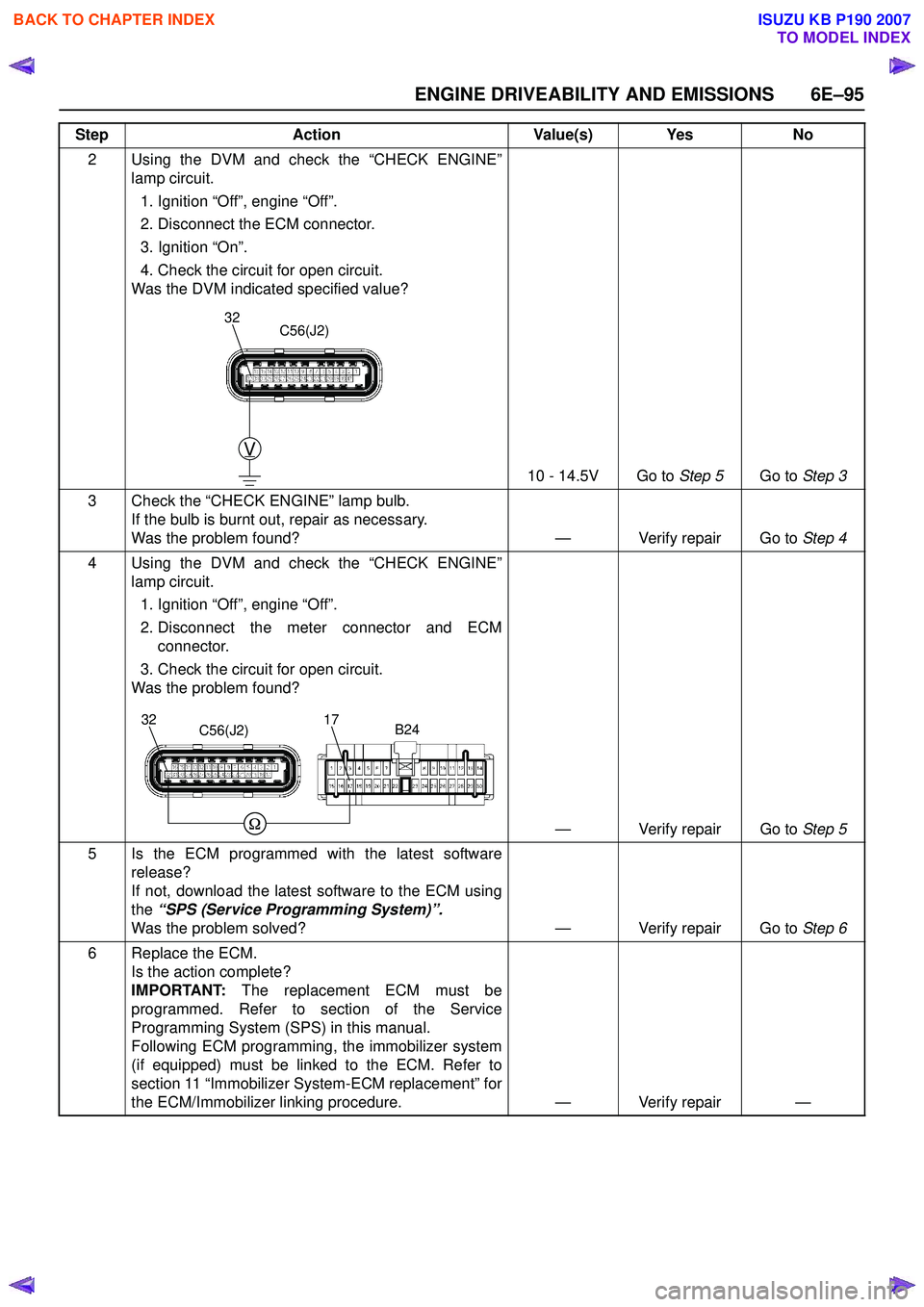
ENGINE DRIVEABILITY AND EMISSIONS 6E–95
2 Using the DVM and check the “CHECK ENGINE”lamp circuit.
1. Ignition “Off”, engine “Off”.
2. Disconnect the ECM connector.
3. Ignition “On”.
4. Check the circuit for open circuit.
Was the DVM indicated specified value?
10 - 14.5V Go to Step 5Go to Step 3
3 Check the “CHECK ENGINE” lamp bulb. If the bulb is burnt out, repair as necessary.
Was the problem found? — Verify repair Go to Step 4
4 Using the DVM and check the “CHECK ENGINE” lamp circuit.
1. Ignition “Off”, engine “Off”.
2. Disconnect the meter connector and ECM connector.
3. Check the circuit for open circuit.
Was the problem found?
— Verify repair Go to Step 5
5 Is the ECM programmed with the latest software release?
If not, download the latest software to the ECM using
the “SPS (Service Programming System)”.
Was the problem solved? — Verify repair Go to Step 6
6 Replace the ECM. Is the action complete?
IMPORTANT: The replacement ECM must be
programmed. Refer to section of the Service
Programming System (SPS) in this manual.
Following ECM programming, the immobilizer system
(if equipped) must be linked to the ECM. Refer to
section 11 “Immobilizer System-ECM replacement” for
the ECM/Immobilizer linking procedure. — Verify repair —
Step
Action Value(s) Yes No
V
32C56(J2)
3217C56(J2)B24
BACK TO CHAPTER INDEX
TO MODEL INDEX
ISUZU KB P190 2007
Page 2267 of 6020

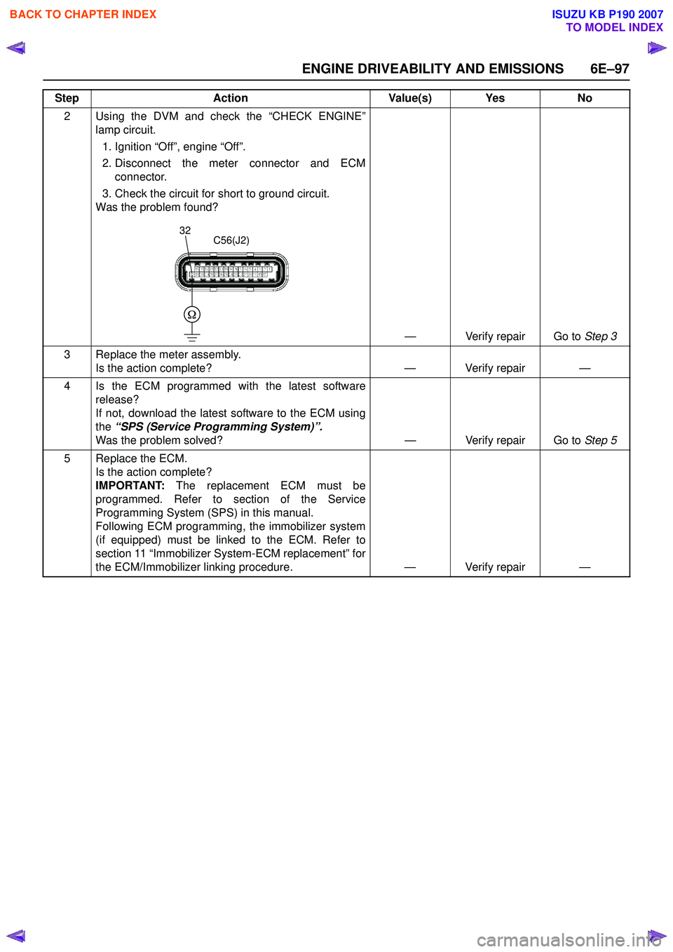
ENGINE DRIVEABILITY AND EMISSIONS 6E–97
2 Using the DVM and check the “CHECK ENGINE”lamp circuit.
1. Ignition “Off”, engine “Off”.
2. Disconnect the meter connector and ECM connector.
3. Check the circuit for short to ground circuit.
Was the problem found?
— Verify repair Go to Step 3
3 Replace the meter assembly. Is the action complete? — Verify repair —
4 Is the ECM programmed with the latest software release?
If not, download the latest software to the ECM using
the “SPS (Service Programming System)”.
Was the problem solved? — Verify repair Go to Step 5
5 Replace the ECM. Is the action complete?
IMPORTANT: The replacement ECM must be
programmed. Refer to section of the Service
Programming System (SPS) in this manual.
Following ECM programming, the immobilizer system
(if equipped) must be linked to the ECM. Refer to
section 11 “Immobilizer System-ECM replacement” for
the ECM/Immobilizer linking procedure. — Verify repair —
Step
Action Value(s) Yes No
32C56(J2)
BACK TO CHAPTER INDEX
TO MODEL INDEX
ISUZU KB P190 2007
Page 2277 of 6020
ENGINE DRIVEABILITY AND EMISSIONS 6E–107
17 Replace the ECM. Is the action complete?
IMPORTANT: The replacement ECM must be
programmed. Refer to section of the Service
Programming System (SPS) in this manual.
Following ECM programming, the immobilizer system
(if equipped) must be linked to the ECM. Refer to
section 11 “Immobilizer System-ECM replacement” for
the ECM/Immobilizer linking procedure. — Verify repair —
Step
Action Value(s) Yes No
BACK TO CHAPTER INDEX
TO MODEL INDEX
ISUZU KB P190 2007
Page 2288 of 6020

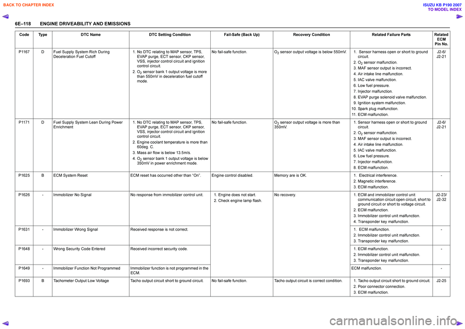
6E–118 ENGINE DRIVEABILITY AND EMISSIONSP1167 D Fuel Supply System Rich During
Deceleration Fuel Cutoff 1. No DTC relating to MAP sensor, TPS,
EVAP purge, ECT sensor, CKP sensor,
VSS, injector control circuit and ignition
control circuit.
2. O
2 sensor bank 1 output voltage is more
than 550mV in deceleration fuel cutoff
mode. No fail-safe function.
O
2 sensor output voltage is below 550mV. 1. Sensor harness open or short to ground
circuit.
2. O
2 sensor malfunction.
3. MAF sensor output is incorrect.
4. Air intake line malfunction.
5. IAC valve malfunction.
6. Low fuel pressure.
7. Injector malfunction.
8. EVAP purge solenoid valve malfunction.
9. Ignition system malfunction.
10. Spark plug malfunction. 11. ECM malfunction. J2-6/
J2-21
P1171 D Fuel Supply System Lean During Power Enrichment 1. No DTC relating to MAP sensor, TPS,
EVAP purge, ECT sensor, CKP sensor,
VSS, injector control circuit and ignition
control circuit.
2. Engine coolant temperature is more than 60deg. C.
3. Mass air flow is below 13.5m/s.
4. O
2 sensor bank 1 output voltage is below
350mV in power enrichment mode. No fail-safe function.
O
2 sensor output voltage is more than
350mV. 1. Sensor harness open or short to ground
circuit.
2. O
2 sensor malfunction.
3. MAF sensor output is incorrect.
4. Air intake line malfunction.
5. IAC valve malfunction.
6. Low fuel pressure.
7. Injector malfunction.
8. ECM malfunction. J2-6/
J2-21
P1625 B ECM System Reset ECM reset has occurred other than “On ”. Engine control disabled. Memory are is OK. 1. Electrical interference.
2. Magnetic interference.
3. ECM malfunction. -
P1626 - Immobilizer No Signal No response from immobilizer control unit. 1. Engine does not start.
2. Check engine lamp flash.No recovery.
1. ECM and immobilizer control unit
communication circuit open circuit, short to
ground circuit or short to voltage circuit.
2. ECM malfunction.
3. Immobilizer control unit malfunction.
4. Transponder key malfunction. J2-23/
J2-32
P1631 - Immobilizer Wrong Signal Received response is not correct. 1. ECM malfunction.
2. Immobilizer control unit malfunction.
3. Transponder key malfunction. -
P1648 - Wrong Security Code Entered Received incorrect security code. 1. ECM malfunction.
2. Immobilizer control unit malfunction.
3. Transponder key malfunction. -
P1649 - Immobilizer Function Not Programmed Immobilizer function is not programmed in the ECM. ECM malfunction.
-
P1693 B Tachometer Output Low Voltage Tacho output circuit short to ground circuit. No fail-safe function. Tacho output circuit is correct condition. 1. Tacho output circuit short to ground circuit.
2. Poor connector connection.
3. ECM malfunction. J2-25
Code Type
DTC Name DTC Setting Condition Fail-Safe (Back Up)Recovery Condition Related Failure PartsRelated
ECM
Pin No.
BACK TO CHAPTER INDEX
TO MODEL INDEX
ISUZU KB P190 2007
Page 2292 of 6020
6E–122 ENGINE DRIVEABILITY AND EMISSIONS
12 Replace the ECM. Is the action complete?
IMPORTANT: The replacement ECM must be
programmed. Refer to section of the Service
Programming System (SPS) in this manual.
Following ECM programming, the immobilizer system
(if equipped) must be linked to the ECM. Refer to
section 11 “Immobilizer System-ECM replacement” for
the ECM/Immobilizer linking procedure. — Verify repair —
Step
Action Value(s) Yes No
BACK TO CHAPTER INDEX
TO MODEL INDEX
ISUZU KB P190 2007
Page 2296 of 6020

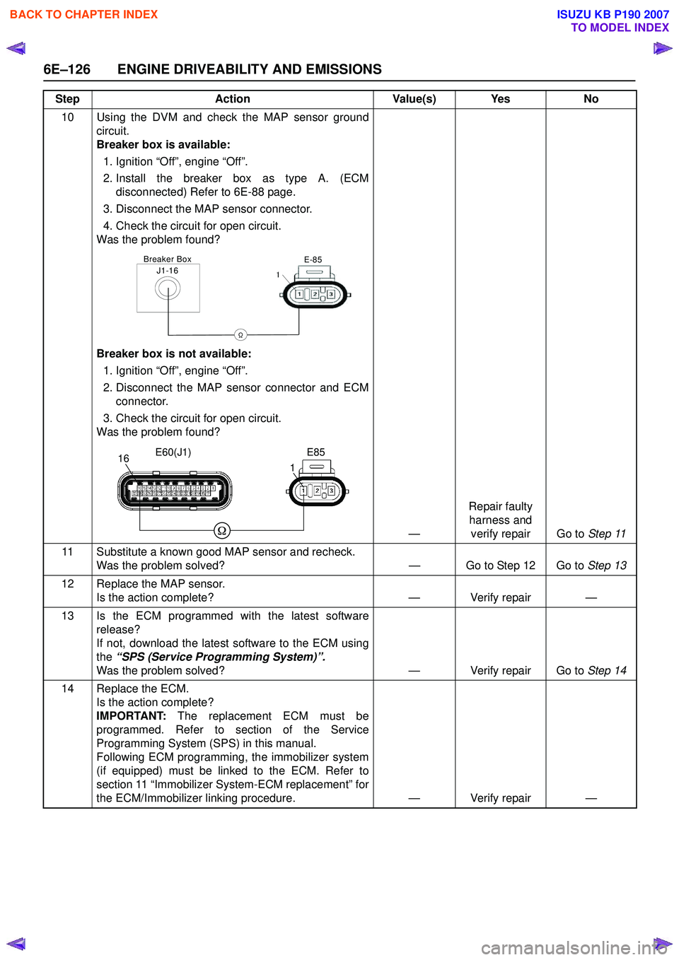
6E–126 ENGINE DRIVEABILITY AND EMISSIONS
10 Using the DVM and check the MAP sensor groundcircuit.
Breaker box is available:
1. Ignition “Off”, engine “Off”.
2. Install the breaker box as type A. (ECM disconnected) Refer to 6E-88 page.
3. Disconnect the MAP sensor connector.
4. Check the circuit for open circuit.
Was the problem found?
Breaker box is not available:
1. Ignition “Off”, engine “Off”.
2. Disconnect the MAP sensor connector and ECM connector.
3. Check the circuit for open circuit.
Was the problem found?
—Repair faulty
harness and verify repair Go to Step 11
11 Substitute a known good MAP sensor and recheck. Was the problem solved? — Go to Step 12 Go to Step 13
12 Replace the MAP sensor. Is the action complete? — Verify repair —
13 Is the ECM programmed with the latest software release?
If not, download the latest software to the ECM using
the “SPS (Service Programming System)”.
Was the problem solved? — Verify repair Go to Step 14
14 Replace the ECM. Is the action complete?
IMPORTANT: The replacement ECM must be
programmed. Refer to section of the Service
Programming System (SPS) in this manual.
Following ECM programming, the immobilizer system
(if equipped) must be linked to the ECM. Refer to
section 11 “Immobilizer System-ECM replacement” for
the ECM/Immobilizer linking procedure. — Verify repair —
Step
Action Value(s) Yes No
J1-16
Breaker Box
Ω
E-85
1
116E85
E60(J1)
BACK TO CHAPTER INDEX
TO MODEL INDEX
ISUZU KB P190 2007
Page 2300 of 6020
6E–130 ENGINE DRIVEABILITY AND EMISSIONS
8 Substitute a known good IAT sensor assembly andrecheck.
Was the problem solved? — Go to Step 9Go to Step 10
9 Replace the IAT sensor assembly. Is the action complete? — Verify repair —
10 Is the ECM programmed with the latest software release?
If not, download the latest software to the ECM using
the “SPS (Service Programming System)”.
Was the problem solved? — Verify repair Go to Step 11
11 Replace the ECM. Is the action complete?
IMPORTANT: The replacement ECM must be
programmed. Refer to section of the Service
Programming System (SPS) in this manual.
Following ECM programming, the immobilizer system
(if equipped) must be linked to the ECM. Refer to
section 11 “Immobilizer System-ECM replacement” for
the ECM/Immobilizer linking procedure. — Verify repair —
Step
Action Value(s) Yes No
BACK TO CHAPTER INDEX
TO MODEL INDEX
ISUZU KB P190 2007