2007 ISUZU KB P190 Immobilizer
[x] Cancel search: ImmobilizerPage 2305 of 6020
ENGINE DRIVEABILITY AND EMISSIONS 6E–135
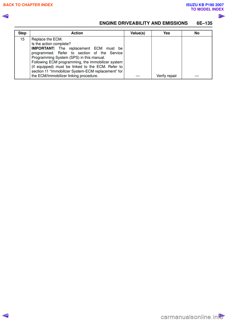
15 Replace the ECM. Is the action complete?
IMPORTANT: The replacement ECM must be
programmed. Refer to section of the Service
Programming System (SPS) in this manual.
Following ECM programming, the immobilizer system
(if equipped) must be linked to the ECM. Refer to
section 11 “Immobilizer System-ECM replacement” for
the ECM/Immobilizer linking procedure. — Verify repair —
Step
Action Value(s) Yes No
BACK TO CHAPTER INDEX
TO MODEL INDEX
ISUZU KB P190 2007
Page 2308 of 6020
6E–138 ENGINE DRIVEABILITY AND EMISSIONS
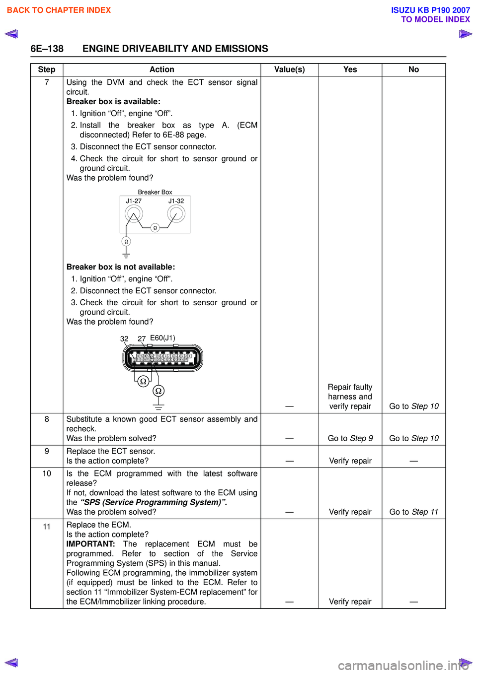
7 Using the DVM and check the ECT sensor signalcircuit.
Breaker box is available:
1. Ignition “Off”, engine “Off”.
2. Install the breaker box as type A. (ECM disconnected) Refer to 6E-88 page.
3. Disconnect the ECT sensor connector.
4. Check the circuit for short to sensor ground or ground circuit.
Was the problem found?
Breaker box is not available: 1. Ignition “Off”, engine “Off”.
2. Disconnect the ECT sensor connector.
3. Check the circuit for short to sensor ground or ground circuit.
Was the problem found?
—Repair faulty
harness and verify repair Go to Step 10
8 Substitute a known good ECT sensor assembly and recheck.
Was the problem solved? — Go to Step 9Go to Step 10
9 Replace the ECT sensor. Is the action complete? — Verify repair —
10 Is the ECM programmed with the latest software release?
If not, download the latest software to the ECM using
the “SPS (Service Programming System)”.
Was the problem solved? — Verify repair Go to Step 11
11 Replace the ECM.
Is the action complete?
IMPORTANT: The replacement ECM must be
programmed. Refer to section of the Service
Programming System (SPS) in this manual.
Following ECM programming, the immobilizer system
(if equipped) must be linked to the ECM. Refer to
section 11 “Immobilizer System-ECM replacement” for
the ECM/Immobilizer linking procedure. — Verify repair —
Step
Action Value(s) Yes No
J1-27J1-32
Ω
Breaker Box
Ω
E60(J1)
2732
BACK TO CHAPTER INDEX
TO MODEL INDEX
ISUZU KB P190 2007
Page 2312 of 6020
6E–142 ENGINE DRIVEABILITY AND EMISSIONS
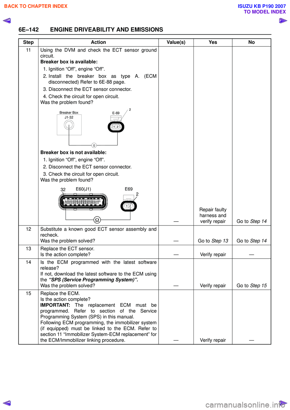
11 Using the DVM and check the ECT sensor groundcircuit.
Breaker box is available:
1. Ignition “Off”, engine “Off”.
2. Install the breaker box as type A. (ECM disconnected) Refer to 6E-88 page.
3. Disconnect the ECT sensor connector.
4. Check the circuit for open circuit.
Was the problem found?
Breaker box is not available: 1. Ignition “Off”, engine “Off”.
2. Disconnect the ECT sensor connector.
3. Check the circuit for open circuit.
Was the problem found?
—Repair faulty
harness and verify repair Go to Step 14
12 Substitute a known good ECT sensor assembly and recheck.
Was the problem solved? — Go to Step 13Go to Step 14
13 Replace the ECT sensor. Is the action complete? — Verify repair —
14 Is the ECM programmed with the latest software release?
If not, download the latest software to the ECM using
the “SPS (Service Programming System)”.
Was the problem solved? — Verify repair Go to Step 15
15 Replace the ECM. Is the action complete?
IMPORTANT: The replacement ECM must be
programmed. Refer to section of the Service
Programming System (SPS) in this manual.
Following ECM programming, the immobilizer system
(if equipped) must be linked to the ECM. Refer to
section 11 “Immobilizer System-ECM replacement” for
the ECM/Immobilizer linking procedure. — Verify repair —
Step
Action Value(s) Yes No
J1-32Breaker Box
Ω
E-692
232E60(J1)E69
BACK TO CHAPTER INDEX
TO MODEL INDEX
ISUZU KB P190 2007
Page 2316 of 6020
6E–146 ENGINE DRIVEABILITY AND EMISSIONS
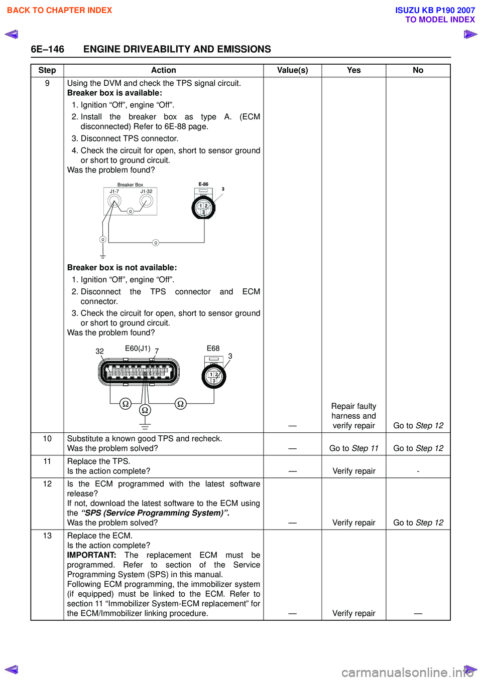
9 Using the DVM and check the TPS signal circuit.Breaker box is available:
1. Ignition “Off”, engine “Off”.
2. Install the breaker box as type A. (ECM disconnected) Refer to 6E-88 page.
3. Disconnect TPS connector.
4. Check the circuit for open, short to sensor ground or short to ground circuit.
Was the problem found?
Breaker box is not available: 1. Ignition “Off”, engine “Off”.
2. Disconnect the TPS connector and ECM connector.
3. Check the circuit for open, short to sensor ground or short to ground circuit.
Was the problem found?
—Repair faulty
harness and verify repair Go to Step 12
10 Substitute a known good TPS and recheck. Was the problem solved? — Go to Step 11Go to Step 12
11 Replace the TPS. Is the action complete? — Verify repair-
12 Is the ECM programmed with the latest software release?
If not, download the latest software to the ECM using
the “SPS (Service Programming System)”.
Was the problem solved? — Verify repair Go to Step 12
13 Replace the ECM. Is the action complete?
IMPORTANT: The replacement ECM must be
programmed. Refer to section of the Service
Programming System (SPS) in this manual.
Following ECM programming, the immobilizer system
(if equipped) must be linked to the ECM. Refer to
section 11 “Immobilizer System-ECM replacement” for
the ECM/Immobilizer linking procedure. — Verify repair —
Step
Action Value(s) Yes No
J1-7J1-32
Ω
Breaker BoxE-86
Ω
3333
Ω
3273E60(J1) E68
BACK TO CHAPTER INDEX
TO MODEL INDEX
ISUZU KB P190 2007
Page 2320 of 6020
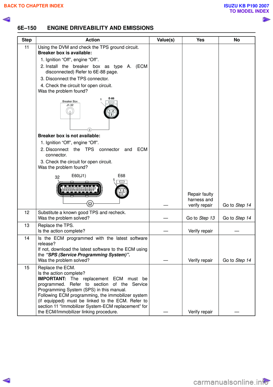
6E–150 ENGINE DRIVEABILITY AND EMISSIONS
11 Using the DVM and check the TPS ground circuit.Breaker box is available:
1. Ignition “Off”, engine “Off”.
2. Install the breaker box as type A. (ECM disconnected) Refer to 6E-88 page.
3. Disconnect the TPS connector.
4. Check the circuit for open circuit.
Was the problem found?
Breaker box is not available: 1. Ignition “Off”, engine “Off”.
2. Disconnect the TPS connector and ECM connector.
3. Check the circuit for open circuit.
Was the problem found?
—Repair faulty
harness and verify repair Go to Step 14
12 Substitute a known good TPS and recheck. Was the problem solved? — Go to Step 13Go to Step 14
13 Replace the TPS. Is the action complete? — Verify repair —
14 Is the ECM programmed with the latest software release?
If not, download the latest software to the ECM using
the “SPS (Service Programming System)”.
Was the problem solved? — Verify repair Go to Step 14
15 Replace the ECM. Is the action complete?
IMPORTANT: The replacement ECM must be
programmed. Refer to section of the Service
Programming System (SPS) in this manual.
Following ECM programming, the immobilizer system
(if equipped) must be linked to the ECM. Refer to
section 11 “Immobilizer System-ECM replacement” for
the ECM/Immobilizer linking procedure. — Verify repair —
Step
Action Value(s) Yes No
J1-32Breaker BoxE-86
Ω
1
11
1
321E60(J1)
E68
BACK TO CHAPTER INDEX
TO MODEL INDEX
ISUZU KB P190 2007
Page 2324 of 6020
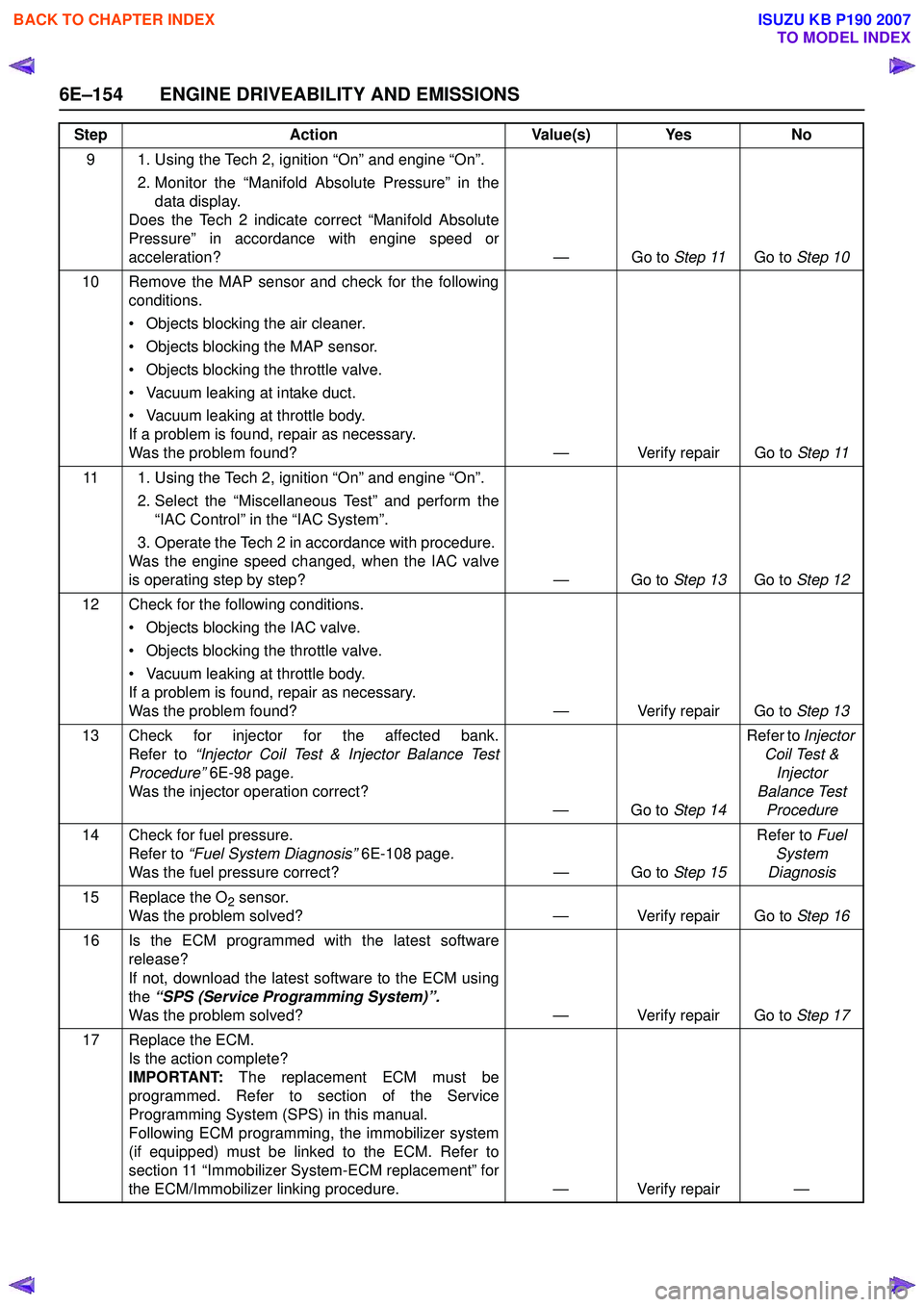
6E–154 ENGINE DRIVEABILITY AND EMISSIONS
9 1. Using the Tech 2, ignition “On” and engine “On”. 2. Monitor the “Manifold Absolute Pressure” in thedata display.
Does the Tech 2 indicate correct “Manifold Absolute
Pressure” in accordance with engine speed or
acceleration? — Go to Step 11Go to Step 10
10 Remove the MAP sensor and check for the following conditions.
• Objects blocking the air cleaner.
• Objects blocking the MAP sensor.
• Objects blocking the throttle valve.
• Vacuum leaking at intake duct.
• Vacuum leaking at throttle body.
If a problem is found, repair as necessary.
Was the problem found? — Verify repair Go to Step 11
11 1. Using the Tech 2, ignition “On” and engine “On”. 2. Select the “Miscellaneous Test” and perform the“IAC Control” in the “IAC System”.
3. Operate the Tech 2 in accordance with procedure.
Was the engine speed changed, when the IAC valve
is operating step by step? — Go to Step 13Go to Step 12
12 Check for the following conditions. • Objects blocking the IAC valve.
• Objects blocking the throttle valve.
• Vacuum leaking at throttle body.
If a problem is found, repair as necessary.
Was the problem found? — Verify repair Go to Step 13
13 Check for injector for the affected bank. Refer to “Injector Coil Test & Injector Balance Test
Procedure” 6E-98 page .
Was the injector operation correct? —Go to Step 14Refer to
Injector
Coil Test & Injector
Balance Test Procedure
14 Check for fuel pressure. Refer to “Fuel System Diagnosis” 6E-108 page.
Was the fuel pressure correct? — Go to Step 15Refer to
Fuel
System
Diagnosis
15 Replace the O
2 sensor.
Was the problem solved? — Verify repair Go to Step 16
16 Is the ECM programmed with the latest software release?
If not, download the latest software to the ECM using
the “SPS (Service Programming System)”.
Was the problem solved? — Verify repair Go to Step 17
17 Replace the ECM. Is the action complete?
IMPORTANT: The replacement ECM must be
programmed. Refer to section of the Service
Programming System (SPS) in this manual.
Following ECM programming, the immobilizer system
(if equipped) must be linked to the ECM. Refer to
section 11 “Immobilizer System-ECM replacement” for
the ECM/Immobilizer linking procedure. — Verify repair —
Step
Action Value(s) Yes No
BACK TO CHAPTER INDEX
TO MODEL INDEX
ISUZU KB P190 2007
Page 2328 of 6020
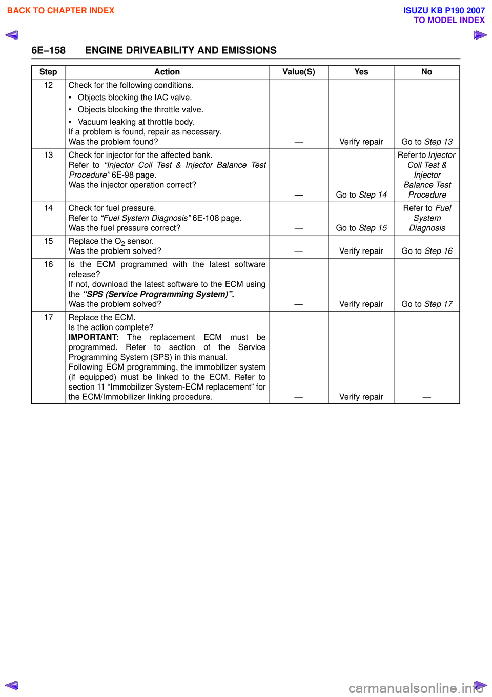
6E–158 ENGINE DRIVEABILITY AND EMISSIONS
12 Check for the following conditions. • Objects blocking the IAC valve.
• Objects blocking the throttle valve.
• Vacuum leaking at throttle body.
If a problem is found, repair as necessary.
Was the problem found? — Verify repair Go to Step 13
13 Check for injector for the affected bank. Refer to “Injector Coil Test & Injector Balance Test
Procedure” 6E-98 page .
Was the injector operation correct? —Go to Step 14Refer to
Injector
Coil Test & Injector
Balance Test Procedure
14 Check for fuel pressure. Refer to “Fuel System Diagnosis” 6E-108 page .
Was the fuel pressure correct? — Go to Step 15Refer to
Fuel
System
Diagnosis
15 Replace the O
2 sensor.
Was the problem solved? — Verify repair Go to Step 16
16 Is the ECM programmed with the latest software release?
If not, download the latest software to the ECM using
the “SPS (Service Programming System)”.
Was the problem solved? — Verify repair Go to Step 17
17 Replace the ECM. Is the action complete?
IMPORTANT: The replacement ECM must be
programmed. Refer to section of the Service
Programming System (SPS) in this manual.
Following ECM programming, the immobilizer system
(if equipped) must be linked to the ECM. Refer to
section 11 “Immobilizer System-ECM replacement” for
the ECM/Immobilizer linking procedure. — Verify repair —
Step
Action Value(S) Yes No
BACK TO CHAPTER INDEX
TO MODEL INDEX
ISUZU KB P190 2007
Page 2332 of 6020
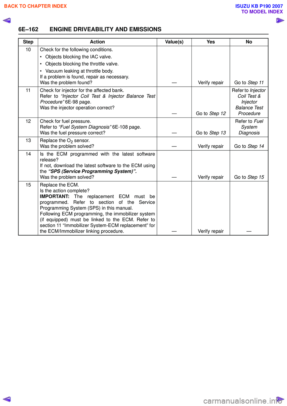
6E–162 ENGINE DRIVEABILITY AND EMISSIONS
10 Check for the following conditions. • Objects blocking the IAC valve.
• Objects blocking the throttle valve.
• Vacuum leaking at throttle body.
If a problem is found, repair as necessary.
Was the problem found? — Verify repair Go to Step 11
11 Check for injector for the affected bank. Refer to “Injector Coil Test & Injector Balance Test
Procedure” 6E-98 page .
Was the injector operation correct? —Go to Step 12Refer to
Injector
Coil Test & Injector
Balance Test Procedure
12 Check for fuel pressure. Refer to “Fuel System Diagnosis” 6E-108 page.
Was the fuel pressure correct? — Go to Step 13Refer to
Fuel
System
Diagnosis
13 Replace the O
2 sensor.
Was the problem solved? — Verify repair Go to Step 14
14 Is the ECM programmed with the latest software release?
If not, download the latest software to the ECM using
the “SPS (Service Programming System)”.
Was the problem solved? — Verify repair Go to Step 15
15 Replace the ECM. Is the action complete?
IMPORTANT: The replacement ECM must be
programmed. Refer to section of the Service
Programming System (SPS) in this manual.
Following ECM programming, the immobilizer system
(if equipped) must be linked to the ECM. Refer to
section 11 “Immobilizer System-ECM replacement” for
the ECM/Immobilizer linking procedure. — Verify repair —
Step
Action Value(s) Yes No
BACK TO CHAPTER INDEX
TO MODEL INDEX
ISUZU KB P190 2007