2007 ISUZU KB P190 CIRCUIT DIAGRAM
[x] Cancel search: CIRCUIT DIAGRAMPage 593 of 6020

BRAKE CON TROL SY STE M 5 A
EHCU, Brake Pipe Diagram .......................................................................................... 5A-5
Hydraulic Unit (H/U) ...................................................................................................... 5A-6
Normal Braking ............................................................................................................. 5A- 7
Pressure Isolation (Pressure Maintain)....................................................................... 5A-8
Pressure Reduction ...................................................................................................... 5A-9
Brake Release ............................................................................................................... 5A -10
Circuit Diagram ............................................................................................................. 5A -11
Connector List ............................................................................................................... 5 A-14
Parts Location ............................................................................................................... 5 A-16
EHCU Pin-Assignment .................................................................................................. 5A-20
System Components .................................................................................................... 5A-22
Electronic Hydraulic Control Unit (EHCU).............................................................. 5A-22
ABS Warning Lamp .................................................................................................. 5A-22
Wheel Speed Sensor (WSS) .................................................................................... 5A-22
G Sensor ................................................................................................................... 5A- 22
Normal and Anti-lock Braking ................................................................................. 5A-22
Electronic Brake-force Distribution (EBD) System................................................ 5A-23
Brake Pedal Travel ................................................................................................... 5A-23
Acronyms and Abbreviations....................................................................................... 5A-23
General Diagnosis ............................................................................................................. 5A-23
General Information ...................................................................................................... 5A-23
ABS Service Precautions ............................................................................................. 5A-23
Computer System Service Precautions ...................................................................... 5A-24
General Service Precautions ....................................................................................... 5A-24
Note on Intermittents .................................................................................................... 5A-24
Test Driving ABS Complaint Vehicles ......................................................................... 5A-24
"ABS" Warning Lamp ................................................................................................... 5A-25
Normal Operation .......................................................................................................... 5A-2 5
SECTION 5A
BRAKE CONTROL SYSTEM
TABLE OF CONTENTS
Ser vice Precau tion ............................................................................................................ 5A -3
General Descrip tio n........................................................................................................... 5A -4
BACK TO CHAPTER INDEX
TO MODEL INDEX
ISUZU KB P190 2007
Page 604 of 6020

BRAKE CONTROL SYSTEM 5A-11
Circuit Diagram
With 4JA1 engine
RTW 78AXF007201
BACK TO CHAPTER INDEX
TO MODEL INDEX
ISUZU KB P190 2007
Page 1004 of 6020

ENGINE ELECTRICAL 6D – 3
GENERAL DESCRIPTION
GENERATOR STARTER MOTOR
066L300004 065L300002
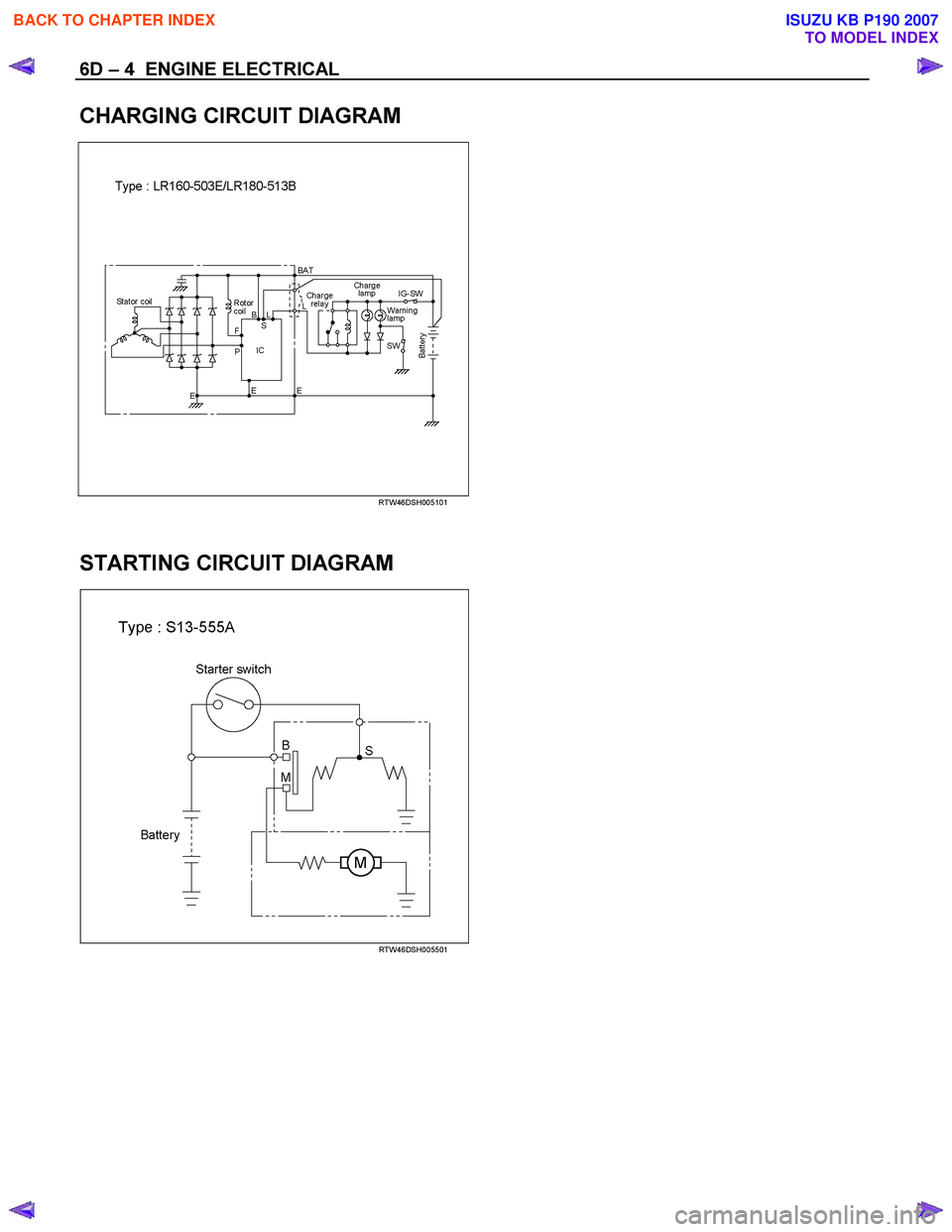
The basic charging system is the IC integral regulator charging system. The internal components are connected
electrically as shown in charging circuit diagram.
The generator features a solid state regulator that is mounted inside the generator. All regulator components are
enclosed into a solid mold, and this unit along with the brush holder assembly is attached to the slip ring end frame.
The generator voltage setting cannot be adjusted.
The starter motor circuit is composed of a 4-pole 4-brush type direct current series motor. The starter motor circuit
utilizes negative ground polarity.
BACK TO CHAPTER INDEX
TO MODEL INDEX
ISUZU KB P190 2007
Page 1005 of 6020
6D – 4 ENGINE ELECTRICAL
CHARGING CIRCUIT DIAGRAM
RTW46DSH005101
STARTING CIRCUIT DIAGRAM
RTW46DSH005501
BACK TO CHAPTER INDEX
TO MODEL INDEX
ISUZU KB P190 2007
Page 1034 of 6020
ENGINE ELECTRICAL 6D – 33
PRE-HEATING SYSTEM
INSPECTION AND REPAIR
Make the necessary adjustments, repairs, and part replacement if excessive wear of damage is discovered during
inspection.
VISUAL CHECK
Check the main fuses and glow indicator for damage.
Replace the part(s) if required.
GLOW RELAY
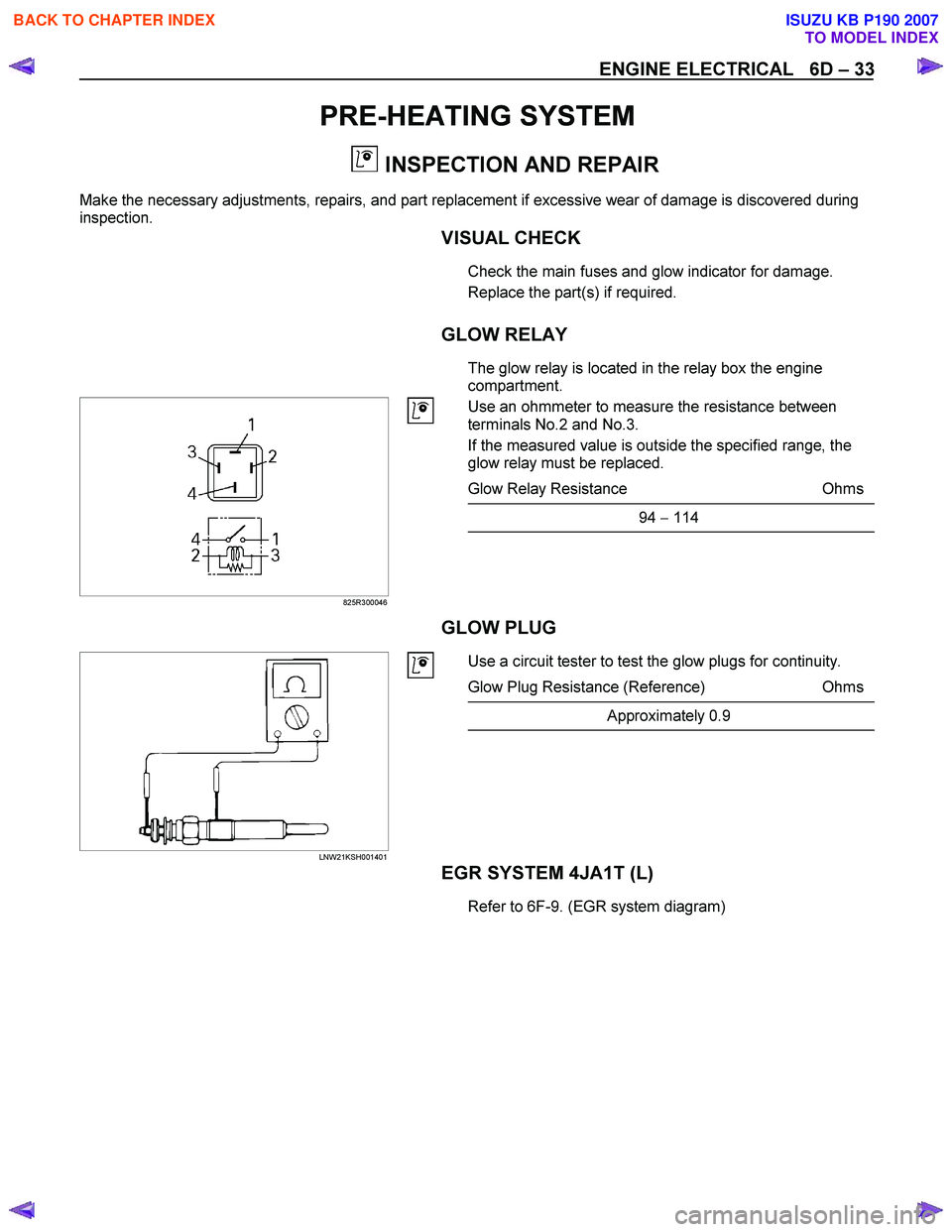
The glow relay is located in the relay box the engine
compartment.
825R300046
Use an ohmmeter to measure the resistance between
terminals No.2 and No.3.
If the measured value is outside the specified range, the
glow relay must be replaced.
Glow Relay Resistance Ohms
94 − 114
GLOW PLUG
LNW21KSH001401
Use a circuit tester to test the glow plugs for continuity.
Glow Plug Resistance (Reference) Ohms
Approximately 0.9
EGR SYSTEM 4JA1T (L)
Refer to 6F-9. (EGR system diagram)
BACK TO CHAPTER INDEX
TO MODEL INDEX
ISUZU KB P190 2007
Page 1589 of 6020
ENGINE ELECTRICAL (4JK1/4JJ1) 6D-1
SECTION 6D
ENGINE ELECTRICAL
TABLE OF CONTENTS
Charging System ................................................ 6D-2
Servicing Cautions .......................................... 6D-2
Important Generator Components and
Function.......................................................... 6D-2
Troubleshooting .............................................. 6D-5
Diagnosis......................................................... 6D-7
Specifications .................................................. 6D-8
Unit Se rv ic ing (4 JJ 1) ....................................... .... ..6D -9
Disassembly .................................................... 6D-10
Inspection and Repair ..................................... 6D-11 Rotor Assembly ........................................... 6D-11
Stator Coil .................................................... 6D-12
Brushes ....................................................... 6D-12
Rectifier ....................................................... 6D-13
Regulator Assembly..................................... 6D-13
Measuring Procedure .................................. 6D-13
Reassembly..................................................... 6D-14
Final Assembly ................................................ 6D-14
Starter Motor ...................................................... 6D-15 Starting Circuit Diagram .................................. 6D-15
Removal and Installation ................................. 6D-15 Important Operations – Removal................. 6D-15
Important Operations – Installation.............. 6D-15
Disassembly .................................................... 6D-16 Disassembly Steps ...................................... 6D-16
Important Operations ................................... 6D-17
Inspection and Repair ..................................... 6D-20 Armature ...................................................... 6D-20
Yoke............................................................. 6D-21
Brush and Brush Holder .............................. 6D-22
Overrunning Clutch...................................... 6D-22
Bearing ........................................................ 6D-23
Reassembly..................................................... 6D-24 Reassembly Steps ....................................... 6D-24
Important Operations ................................... 6D-25
Inspection After Assembly ........................... 6D-26
Magnetic Switch .............................................. 6D-27
Torque Specifications...................................... 6D-28
Pre-Heating System ........................................... 6D-29 Inspection and Repair ..................................... 6D-29 Visual Check................................................ 6D-29
Glow Relay .................................................. 6D-29
Glow Plug .................................................... 6D-29
BACK TO CHAPTER INDEX
TO MODEL INDEX
ISUZU KB P190 2007
Page 1603 of 6020
ENGINE ELECTRICAL (4JK1/4JJ1) 6D-15
Starter Motor
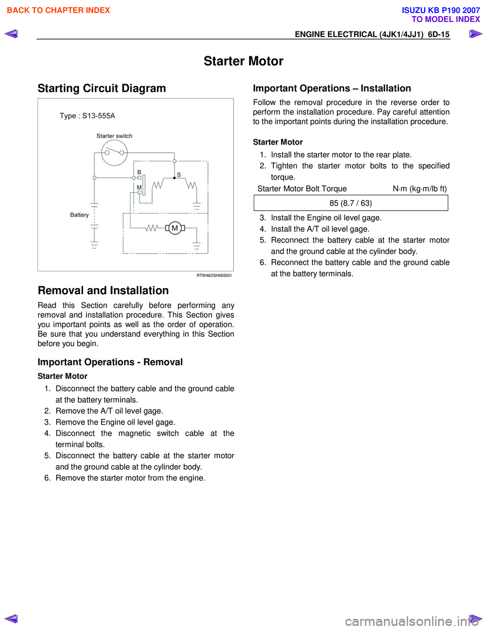
Starting Circuit Diagram
RTW 46DSH005501
Removal and Installation
Read this Section carefully before performing any
removal and installation procedure. This Section gives
you important points as well as the order of operation.
Be sure that you understand everything in this Section
before you begin.
Important Operations - Removal
Starter Motor
1. Disconnect the battery cable and the ground cable at the battery terminals.
2. Remove the A/T oil level gage.
3. Remove the Engine oil level gage.
4. Disconnect the magnetic switch cable at the terminal bolts.
5. Disconnect the battery cable at the starter moto
r
and the ground cable at the cylinder body.
6. Remove the starter motor from the engine.
Important Operations – Installation
Follow the removal procedure in the reverse order to
perform the installation procedure. Pay careful attention
to the important points during the installation procedure.
Starter Motor
1. Install the starter motor to the rear plate.
2. Tighten the starter motor bolts to the specified torque.
Starter Motor Bolt Torque N⋅m (kg ⋅m/lb ft)
85 (8.7 / 63)
3. Install the Engine oil level gage.
4. Install the A/T oil level gage.
5. Reconnect the battery cable at the starter moto
r
and the ground cable at the cylinder body.
6. Reconnect the battery cable and the ground cable at the battery terminals.
BACK TO CHAPTER INDEX
TO MODEL INDEX
ISUZU KB P190 2007
Page 1688 of 6020
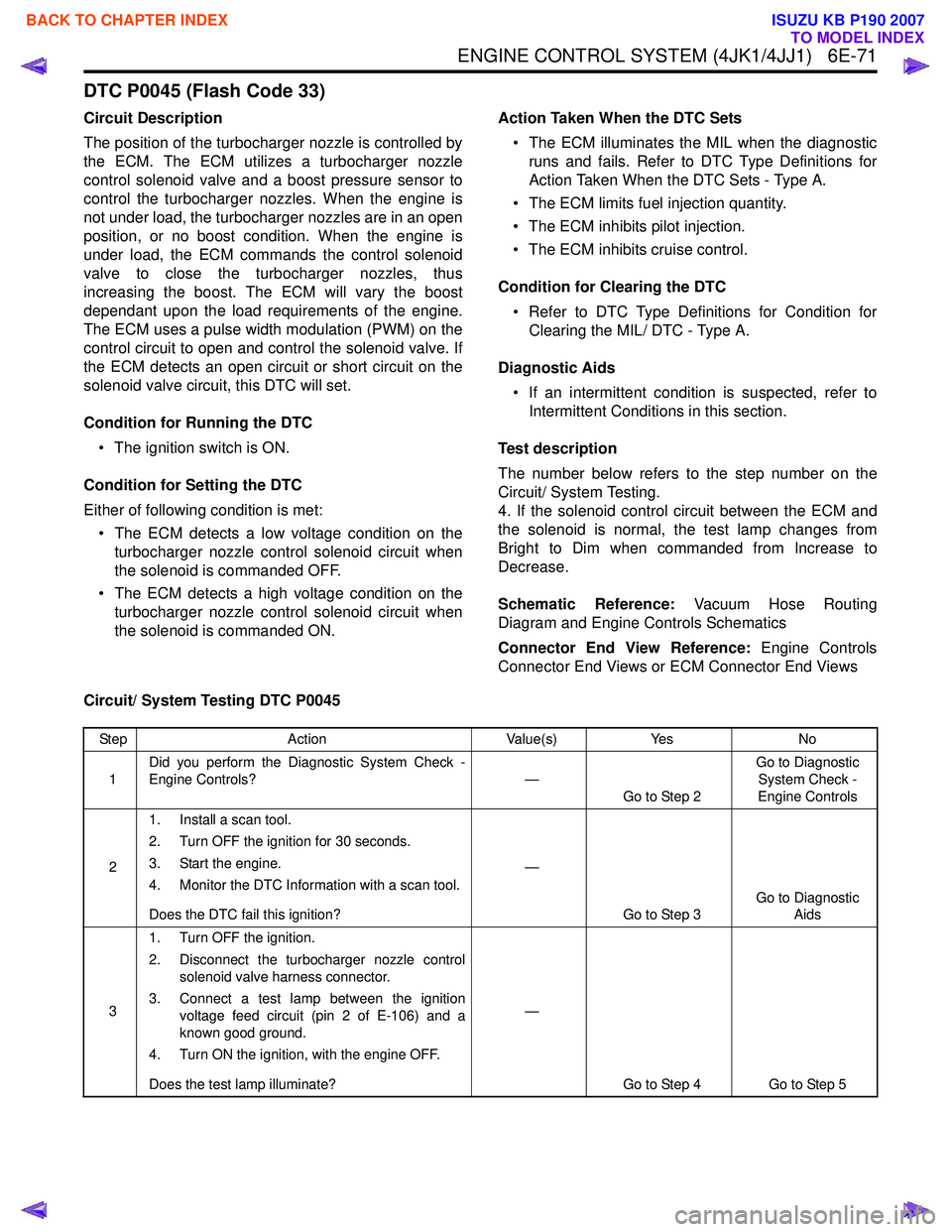
ENGINE CONTROL SYSTEM (4JK1/4JJ1) 6E-71
DTC P0045 (Flash Code 33)
Circuit Description
The position of the turbocharger nozzle is controlled by
the ECM. The ECM utilizes a turbocharger nozzle
control solenoid valve and a boost pressure sensor to
control the turbocharger nozzles. When the engine is
not under load, the turbocharger nozzles are in an open
position, or no boost condition. When the engine is
under load, the ECM commands the control solenoid
valve to close the turbocharger nozzles, thus
increasing the boost. The ECM will vary the boost
dependant upon the load requirements of the engine.
The ECM uses a pulse width modulation (PWM) on the
control circuit to open and control the solenoid valve. If
the ECM detects an open circuit or short circuit on the
solenoid valve circuit, this DTC will set.
Condition for Running the DTC • The ignition switch is ON.
Condition for Setting the DTC
Either of following condition is met: • The ECM detects a low voltage condition on the turbocharger nozzle control solenoid circuit when
the solenoid is commanded OFF.
• The ECM detects a high voltage condition on the turbocharger nozzle control solenoid circuit when
the solenoid is commanded ON. Action Taken When the DTC Sets
• The ECM illuminates the MIL when the diagnostic runs and fails. Refer to DTC Type Definitions for
Action Taken When the DTC Sets - Type A.
• The ECM limits fuel injection quantity.
• The ECM inhibits pilot injection.
• The ECM inhibits cruise control.
Condition for Clearing the DTC • Refer to DTC Type Definitions for Condition for Clearing the MIL/ DTC - Type A.
Diagnostic Aids • If an intermittent condition is suspected, refer to Intermittent Conditions in this section.
Test description
The number below refers to the step number on the
Circuit/ System Testing.
4. If the solenoid control circuit between the ECM and
the solenoid is normal, the test lamp changes from
Bright to Dim when commanded from Increase to
Decrease.
Schematic Reference: Vacuum Hose Routing
Diagram and Engine Controls Schematics
Connector End View Reference: Engine Controls
Connector End Views or ECM Connector End Views
Circuit/ System Testing DTC P0045
Step Action Value(s)Yes No
1 Did you perform the Diagnostic System Check -
Engine Controls? —
Go to Step 2 Go to Diagnostic
System Check -
Engine Controls
2 1. Install a scan tool.
2. Turn OFF the ignition for 30 seconds.
3. Start the engine.
4. Monitor the DTC Information with a scan tool.
Does the DTC fail this ignition? —
Go to Step 3 Go to Diagnostic
Aids
3 1. Turn OFF the ignition.
2. Disconnect the turbocharger nozzle control solenoid valve harness connector.
3. Connect a test lamp between the ignition voltage feed circuit (pin 2 of E-106) and a
known good ground.
4. Turn ON the ignition, with the engine OFF.
Does the test lamp illuminate? —
Go to Step 4 Go to Step 5
BACK TO CHAPTER INDEX
TO MODEL INDEX
ISUZU KB P190 2007