2007 ISUZU KB P190 CIRCUIT DIAGRAM
[x] Cancel search: CIRCUIT DIAGRAMPage 1849 of 6020
6E-232 ENGINE CONTROL SYSTEM (4JK1/4JJ1)
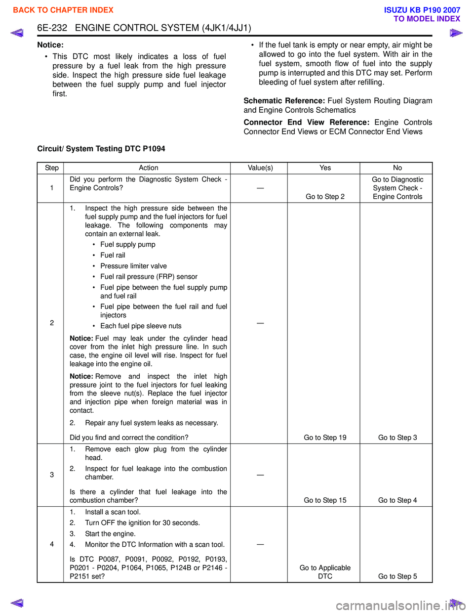
Notice:• This DTC most likely indicates a loss of fuel pressure by a fuel leak from the high pressure
side. Inspect the high pressure side fuel leakage
between the fuel supply pump and fuel injector
first. • If the fuel tank is empty or near empty, air might be
allowed to go into the fuel system. With air in the
fuel system, smooth flow of fuel into the supply
pump is interrupted and this DTC may set. Perform
bleeding of fuel system after refilling.
Schematic Reference: Fuel System Routing Diagram
and Engine Controls Schematics
Connector End View Reference: Engine Controls
Connector End Views or ECM Connector End Views
Circuit/ System Testing DTC P1094
Step Action Value(s)Yes No
1 Did you perform the Diagnostic System Check -
Engine Controls? —
Go to Step 2 Go to Diagnostic
System Check -
Engine Controls
2 1. Inspect the high pressure side between the
fuel supply pump and the fuel injectors for fuel
leakage. The following components may
contain an external leak.
• Fuel supply pump
• Fuel rail
• Pressure limiter valve
• Fuel rail pressure (FRP) sensor
• Fuel pipe between the fuel supply pump and fuel rail
• Fuel pipe between the fuel rail and fuel injectors
• Each fuel pipe sleeve nuts
Notice: Fuel may leak under the cylinder head
cover from the inlet high pressure line. In such
case, the engine oil level will rise. Inspect for fuel
leakage into the engine oil.
Notice: Remove and inspect the inlet high
pressure joint to the fuel injectors for fuel leaking
from the sleeve nut(s). Replace the fuel injector
and injection pipe when foreign material was in
contact.
2. Repair any fuel system leaks as necessary.
Did you find and correct the condition? —
Go to Step 19 Go to Step 3
3 1. Remove each glow plug from the cylinder
head.
2. Inspect for fuel leakage into the combustion chamber.
Is there a cylinder that fuel leakage into the
combustion chamber? —
Go to Step 15 Go to Step 4
4 1. Install a scan tool.
2. Turn OFF the ignition for 30 seconds.
3. Start the engine.
4. Monitor the DTC Information with a scan tool.
Is DTC P0087, P0091, P0092, P0192, P0193,
P0201 - P0204, P1064, P1065, P124B or P2146 -
P2151 set? —
Go to Applicable DTC Go to Step 5
BACK TO CHAPTER INDEX
TO MODEL INDEX
ISUZU KB P190 2007
Page 2156 of 6020
6D3-8 STARTING AND CHARGING SYSTEM
General On-Vehicle Inspection
The operating condition of charging system is indicated by the
charge warning lamp. The warning lamp comes on when the
starter switch is turned to "ON" position. The charging system
operates normally if the lamp goes off when the engine starts.
If the warning lamp shows abnormality or if undercharged or
overcharged battery condition is suspected, perform diagnosis
by checking the charging system as follows:
1. Check visually the belt and wiring connector.
2. W ith the engine stopped, turn the stator switch to "ON" position and observe the warning lamp.
If lamp does not come on:
Disconnect wiring connector from generator, and ground the terminal "L" on connector side.
If lamp comes on:
Repair or replace the generator.
Generator
Removal
1. Disconnect battery ground cable.
2. Move drive belt tensioner to loose side using wrench then remove drive belt.
3. Disconnect terminal "B" wiring connector and connector.
4. Remove generator assembly.
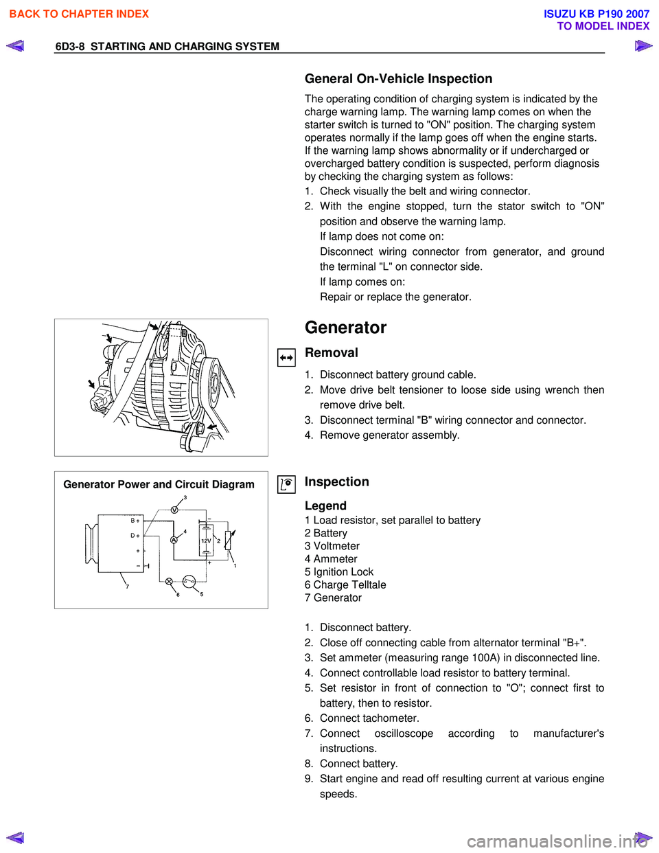
Generator Power and Circuit Diagram
Inspection
Legend
1 Load resistor, set parallel to battery
2 Battery
3 Voltmeter
4 Ammeter
5 Ignition Lock
6 Charge Telltale
7 Generator
1. Disconnect battery.
2. Close off connecting cable from alternator terminal "B+".
3. Set ammeter (measuring range 100A) in disconnected line.
4. Connect controllable load resistor to battery terminal.
5. Set resistor in front of connection to "O"; connect first to battery, then to resistor.
6. Connect tachometer.
7. Connect oscilloscope according to manufacturer's instructions.
8. Connect battery.
9. Start engine and read off resulting current at various engine speeds.
BACK TO CHAPTER INDEX
TO MODEL INDEX
ISUZU KB P190 2007
Page 2157 of 6020
STARTING AND CHARGING SYSTEM 6D3-9
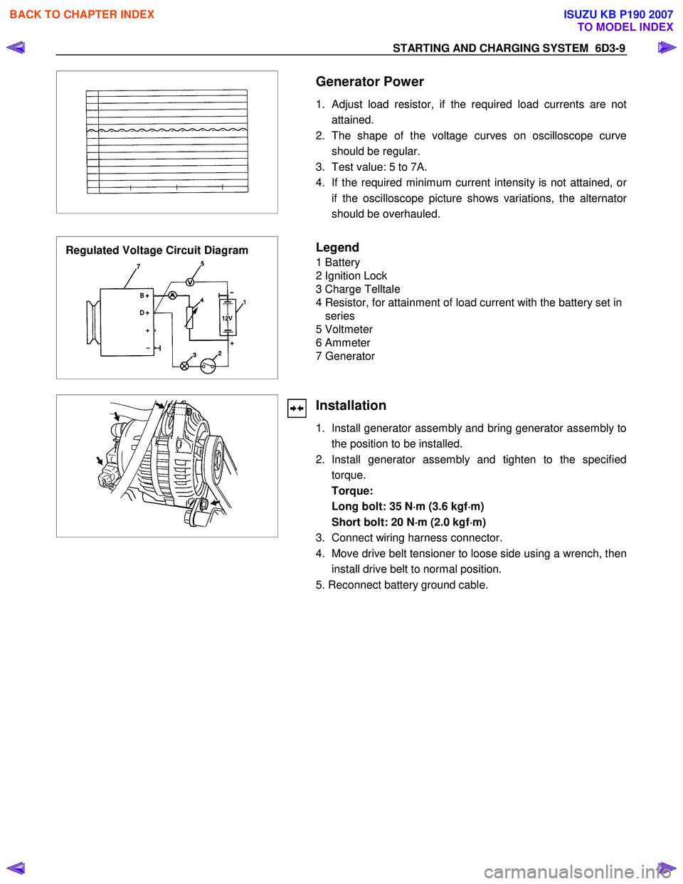
Generator Power
1. Adjust load resistor, if the required load currents are not attained.
2. The shape of the voltage curves on oscilloscope curve should be regular.
3. Test value: 5 to 7A.
4. If the required minimum current intensity is not attained, o
r
if the oscilloscope picture shows variations, the alternator
should be overhauled.
Regulated Voltage Circuit Diagram
Legend
1 Battery
2 Ignition Lock
3 Charge Telltale
4 Resistor, for attainment of load current with the battery set in series
5 Voltmeter
6 Ammeter
7 Generator
Installation
1. Install generator assembly and bring generator assembly to the position to be installed.
2. Install generator assembly and tighten to the specified torque.
Torque:
Long bolt: 35 N ⋅
⋅⋅
⋅
m (3.6 kgf ⋅
⋅⋅
⋅
m)
Short bolt: 20 N ⋅
⋅⋅
⋅
m (2.0 kgf ⋅
⋅⋅
⋅
m)
3. Connect wiring harness connector.
4. Move drive belt tensioner to loose side using a wrench, then install drive belt to normal position.
5. Reconnect battery ground cable.
BACK TO CHAPTER INDEX
TO MODEL INDEX
ISUZU KB P190 2007
Page 2171 of 6020
SECTION 6E
TABLE OF CONTENTS
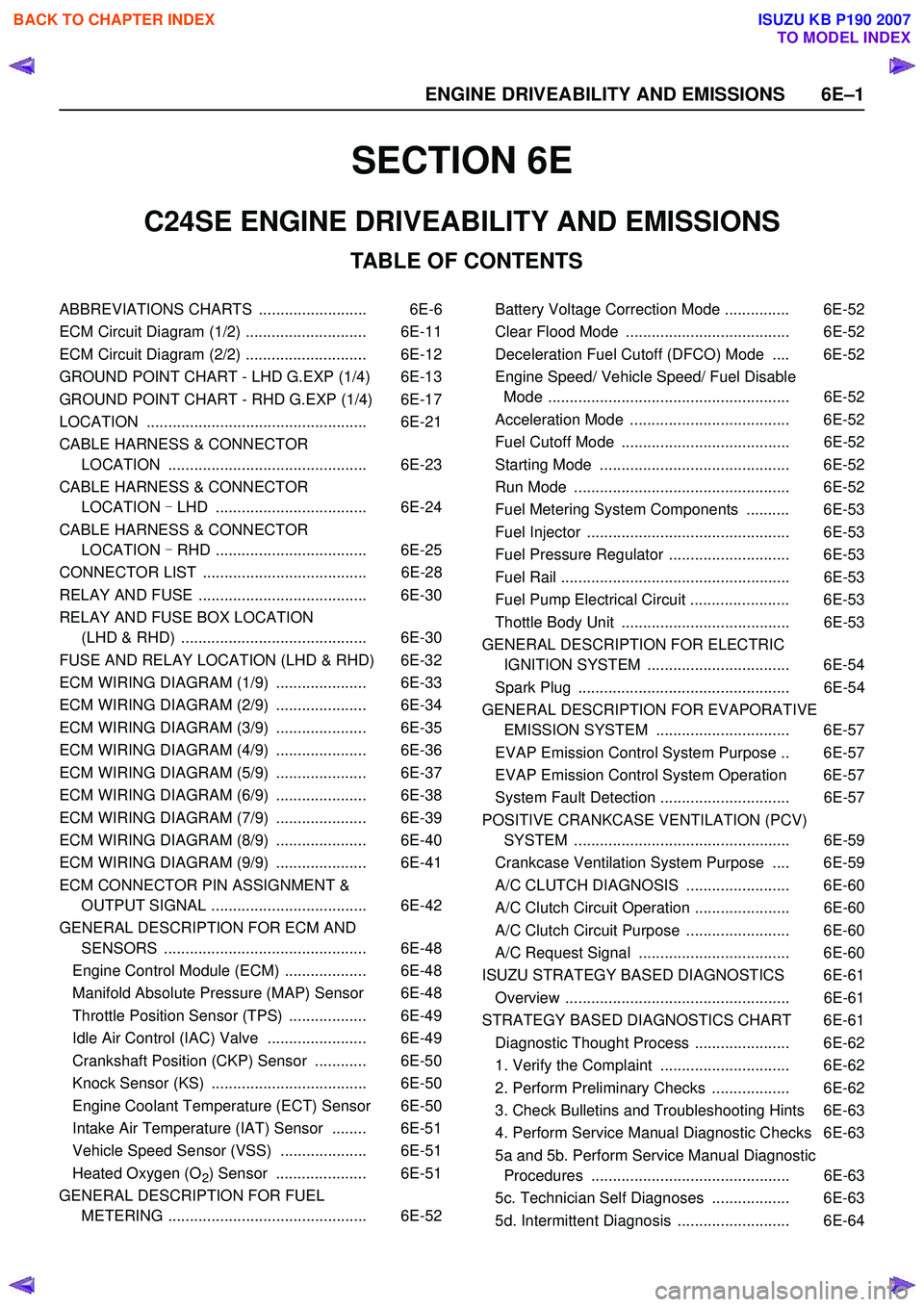
C24SE ENGINE DRIVEABILITY AND EMISSIONS
ABBREVIATIONS CHARTS ......................... 6E-6
ECM Circuit Diagram (1/2) ............................ 6E-11
ECM Circuit Diagram (2/2) ............................ 6E-12
GROUND POINT CHART - LHD G.EXP (1/4) 6E-13
GROUND POINT CHART - RHD G.EXP (1/4) 6E-17
LOCATION ................................................... 6E-21
CABLE HARNESS & CONNECTOR LOCATION .............................................. 6E-23
CABLE HARNESS & CONNECTOR LOCATION - LHD ................................... 6E-24
CABLE HARNESS & CONNECTOR LOCATION - RHD ................................... 6E-25
CONNECTOR LIST ...................................... 6E-28
RELAY AND FUSE ....................................... 6E-30
RELAY AND FUSE BOX LOCATION (LHD & RHD) ........................................... 6E-30
FUSE AND RELAY LOCATION (LHD & RHD) 6E-32
ECM WIRING DIAGRAM (1/9) ..................... 6E-33
ECM WIRING DIAGRAM (2/9) ..................... 6E-34
ECM WIRING DIAGRAM (3/9) ..................... 6E-35
ECM WIRING DIAGRAM (4/9) ..................... 6E-36
ECM WIRING DIAGRAM (5/9) ..................... 6E-37
ECM WIRING DIAGRAM (6/9) ..................... 6E-38
ECM WIRING DIAGRAM (7/9) ..................... 6E-39
ECM WIRING DIAGRAM (8/9) ..................... 6E-40
ECM WIRING DIAGRAM (9/9) ..................... 6E-41
ECM CONNECTOR PIN ASSIGNMENT & OUTPUT SIGNAL .................................... 6E-42
GENERAL DESCRIPTION FOR ECM AND SENSORS ............................................... 6E-48
Engine Control Module (ECM) ................... 6E-48
Manifold Absolute Pressure (MAP) Sensor 6E-48
Throttle Position Sensor (TPS) .................. 6E-49
Idle Air Control (IAC) Valve ....................... 6E-49
Crankshaft Position (CKP) Sensor ............ 6E-50
Knock Sensor (KS) .................................... 6E-50
Engine Coolant Temperature (ECT) Sensor 6E-50
Intake Air Temperature (IAT) Sensor ........ 6E-51
Vehicle Speed Sensor (VSS) .................... 6E-51
Heated Oxygen (O
2) Sensor ..................... 6E-51
GENERAL DESCRIPTION FOR FUEL METERING .............................................. 6E-52 Battery Voltage Correction Mode ............... 6E-52
Clear Flood Mode ...................................... 6E-52
Deceleration Fuel Cutoff (DFCO) Mode .... 6E-52
Engine Speed/ Vehicle Speed/ Fuel Disable Mode ........................................................ 6E-52
Acceleration Mode ..................................... 6E-52
Fuel Cutoff Mode ....................................... 6E-52
Starting Mode ............................................ 6E-52
Run Mode .................................................. 6E-52
Fuel Metering System Components .......... 6E-53
Fuel Injector ............................................... 6E-53
Fuel Pressure Regulator ............................ 6E-53
Fuel Rail ..................................................... 6E-53
Fuel Pump Electrical Circuit ....................... 6E-53
Thottle Body Unit ....................................... 6E-53
GENERAL DESCRIPTION FOR ELECTRIC IGNITION SYSTEM ................................. 6E-54
Spark Plug ................................................. 6E-54
GENERAL DESCRIPTION FOR EVAPORATIVE EMISSION SYSTEM ............................... 6E-57
EVAP Emission Control System Purpose .. 6E-57
EVAP Emission Control System Operation 6E-57
System Fault Detection .............................. 6E-57
POSITIVE CRANKCASE VENTILATION (PCV) SYSTEM .................................................. 6E-59
Crankcase Ventilation System Purpose .... 6E-59
A/C CLUTCH DIAGNOSIS ........................ 6E-60
A/C Clutch Circuit Operation ...................... 6E-60
A/C Clutch Circuit Purpose ........................ 6E-60
A/C Request Signal ................................... 6E-60
ISUZU STRATEGY BASED DIAGNOSTICS 6E-61
Overview .................................................... 6E-61
STRATEGY BASED DIAGNOSTICS CHART 6E-61 Diagnostic Thought Process ...................... 6E-62
1. Verify the Complaint .............................. 6E-62
2. Perform Preliminary Checks .................. 6E-62
3. Check Bulletins and Troubleshooting Hints 6E-63
4. Perform Service Manual Diagnostic Checks 6E-63
5a and 5b. Perform Service Manual Diagnostic Procedures .............................................. 6E-63
5c. Technician Self Diagnoses .................. 6E-63
5d. Intermittent Diagnosis .......................... 6E-64
6 E –1
E N GINE DRIV EABILITY AND E M IS SIONS
BACK TO CHAPTER INDEX
TO MODEL INDEX
ISUZU KB P190 2007
Page 2181 of 6020
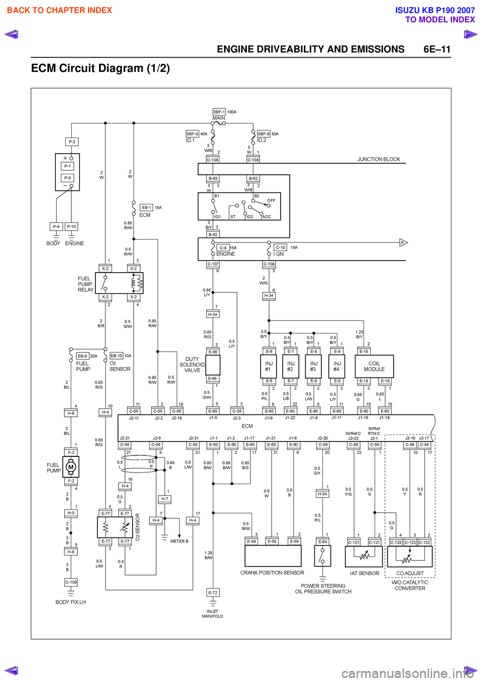
ENGINE DRIVEABILITY AND EMISSIONS 6E–11
ECM Circuit Diagram (1/2)
BACK TO CHAPTER INDEX
TO MODEL INDEX
ISUZU KB P190 2007
Page 2182 of 6020
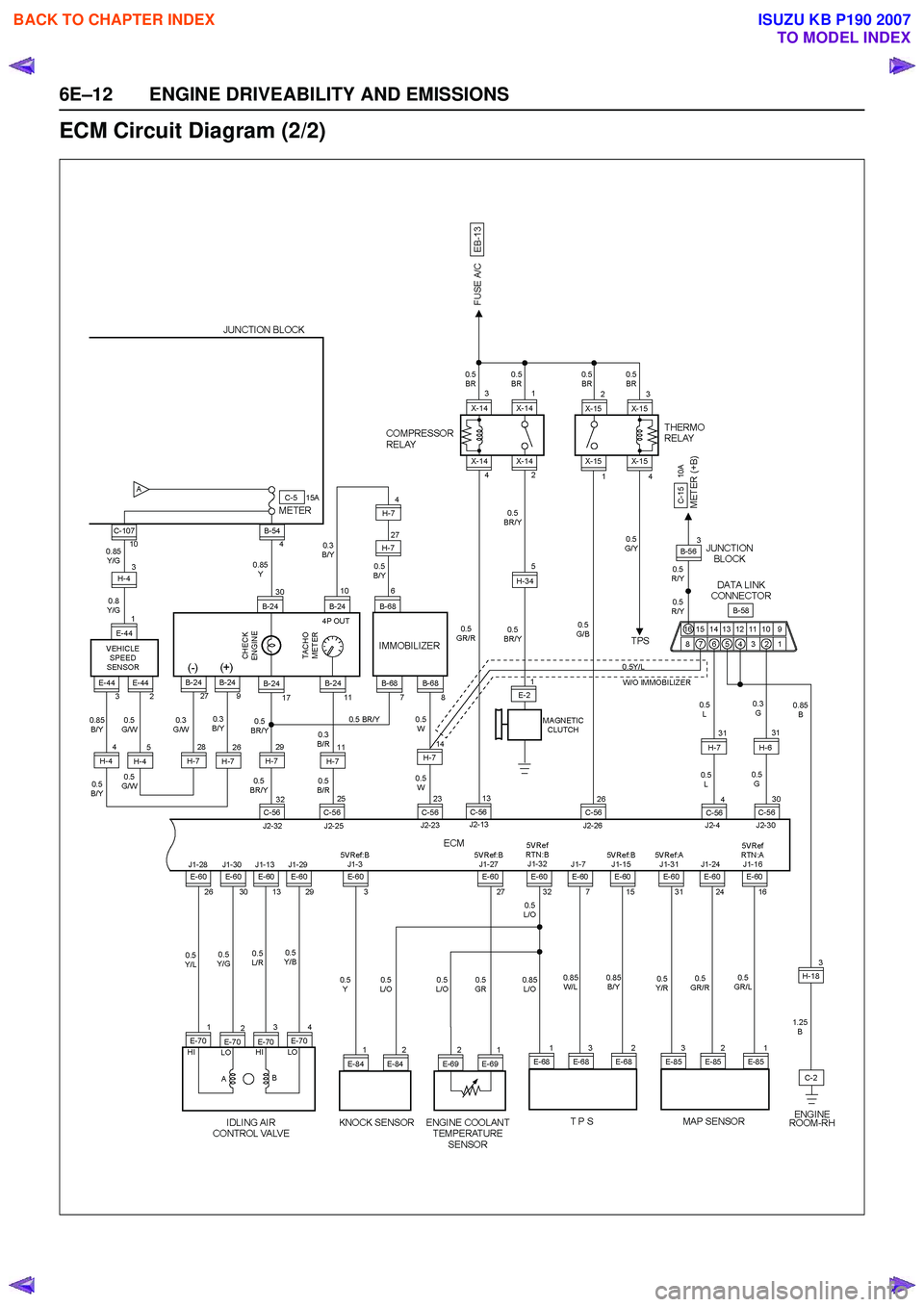
6E–12 ENGINE DRIVEABILITY AND EMISSIONS
ECM Circuit Diagram (2/2)
BACK TO CHAPTER INDEX
TO MODEL INDEX
ISUZU KB P190 2007
Page 2230 of 6020
6E–60 ENGINE DRIVEABILITY AND EMISSIONS
A/C CLUTCH DIAGNOSIS
A/C Clutch Circuit Operation
A 12-volt signal is supplied to the A/C request input of
the ECM when the A/C is selected through the A/C
control switch.
The A/C compressor clutch relay is controlled through
the ECM. This allows the ECM to modify the idle air
control position prior to the A/C clutch engagement for
better idle quality. If the engine operating conditions are
within their specified calibrated acceptable ranges, the
ECM will enable the A/C compressor relay. This is done
by providing a ground path for the A/C relay coil within
the ECM. When the A/C compressor relay is enabled,
battery voltage is supplied to the compressor relay is
enabled, battery voltage is supplied to the compressor
clutch coil.
The ECM will enable the A/C compressor clutch
whenever the engine is running and the A/C has been
requested. The ECM will not enable the A/C
compressor clutch if any of the following conditions are
met:
• The engine speed is greater than 6000 RPM.
• The ECT is greater than 122°C (251°F).
• The throttle is more than 95% open.
A/C Clutch Circuit Purpose
The A/C compressor operation is controlled by the
engine control module (ECM) for the following reasons:
• It improves idle quality during compressor clutch engagement.
• It improves wide open throttle (WOT) performance.
• It provides A/C compressor protection from operation with incorrect refrigerant pressures.
The A/C electrical system consists of the following
components:
• The A/C control switch.
• The A/C refrigerant pressure switches.
• The A/C compressor clutch.
• The A/C compressor clutch relay.
•The ECM.
A/C Request Signal
This signal tells the ECM when the A/C mode is
selected at the A/C control switch. The ECM uses this
input to adjust the idle speed before turning on the A/C
clutch. The A/C compressor will be inoperative if this
signal is not available to the ECM.
Refer to A/C Clutch Circuit Diagnosis for A/C wiring
diagrams and diagnosis for the A/C electrical system.
BACK TO CHAPTER INDEX
TO MODEL INDEX
ISUZU KB P190 2007
Page 2233 of 6020
ENGINE DRIVEABILITY AND EMISSIONS 6E–63
3. Check Bulletins and Troubleshooting Hints
NOTE: As estimated 30 percent of successful vehicle
repairs are diagnosed with this step!
What you should do
You should have enough information gained from
preliminary checks to accurately search for a bulletin
and other related service information. Some service
manual sections provide troubleshooting hints that
match symptoms with specific complaints.
What resources you should use
You should use the following resources for assistance in
checking for bulletins and troubleshooting hints:
• Printed bulletins
• Access ISUZU Bulletin Web site.
• Videotapes
• Service manual
4. Perform Service Manual Diagnostic Checks
What you should do
The “System Checks” in most service manual sections
and in most cells of section 8A (electrical) provide you
with:
• A systematic approach to narrowing down the possible causes of a system fault
• Direction to specific diagnostic procedures in the service manual
• Assistance to identify what systems work correctly
What resources you should use
Whenever possible, you should use the following
resources to perform service manual checks:
• Service manual
• Technical equipment (for viewing DTCs and analyzing data)
• Digital multimeter and circuit testing tools
• Other tools as needed
5a and 5b. Perform Service Manual Diagnostic Procedures
NOTE: An estimated 40 percent of successful vehicle
repairs are diagnosed with these steps!
What you should do
When directed by service manual diagnostic checks,
you must then carefully and accurately perform the
steps of diagnostic procedures to locate the fault related to the customer complaint.
What resources you should use
Whenever appropriate, you should use the following
resources to perform service manual diagnostic
procedures:
• Service manual
• Technical equipment (for analyzing diagnostic data)
• Digital multimeter and circuit testing tools
• Essential and special tools
5c. Technician Self Diagnoses
When there is no DTC stored and no matching
symptom for the condition identified in the service
manual, you must begin with a thorough understanding
of how the system(s) operates. Efficient use of the
service manual combined with you experience and a
good process of elimination will result in accurate
diagnosis of the condition.
What you should do
Step 1: Identify and understand the suspect
circuit(s)
Having completed steps 1 through 4 of the Strategy
Based Diagnostics chart, you should have enough
information to identify the system(s) or sub-system(s)
involved. Using the service manual, you should
determine and investigate the following circuit
characteristics:
• Electrical: – How is the circuit powered (power distributioncharts and/or fuse block details)?
– How is the circuit grounded (ground distribution charts)?
– How is the circuit controlled or sensed (theory of operation):
– If it is a switched circuit, is it normally open or normally closed?
– Is the power switched or is the ground switched?
– Is it a variable resistance circuit (ECT sensor or TP sensor, for example)?
– Is it a signal generating device (MAF sensor of VSS, for example)?
– Does it rely on some mechanical/vacuum device to operate?
•Physical:
– Where are the circuit components (componentlocators and wire harness routing diagrams):
– Are there areas where wires could be chafed or pinched (brackets or frames)?
– Are there areas subjected to extreme temperatures?
BACK TO CHAPTER INDEX
TO MODEL INDEX
ISUZU KB P190 2007