2007 ISUZU KB P190 SECURITY
[x] Cancel search: SECURITYPage 1 of 6020

1
WORKSHOP
REPAIR MANUAL
GE NERAL INFORMATION 0
HEATING AND VENTILATION
BRAKESMAIN INDEX ISUZU
CONTENTS
WHEELS AND TYRES
4
5
BODY 8
SECURITY 11 SUSPENSION
3
STEERING
2
AXLE
FRAME AND CAB
ENGINE
6
TRANSMISSION 7
MY 2007
RESTRAINTS 9
CAB 10
BACK TO FRONT PAGE
KB P190
ISUZU KB P190 2007
Page 1097 of 6020
Engine Control System (4JH1) 6E-63
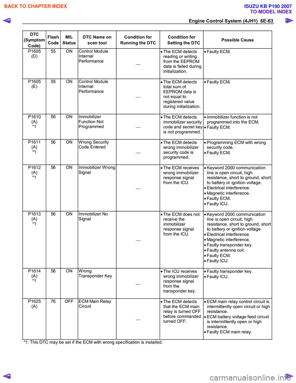
DTC
(Symptom Code) Flash
Code MIL
Status DTC Name on
scan tool Condition for
Running the DTC Condition for
Setting the DTC Possible Cause
P1605
(D) 55 ON Control Module
Internal
Performance •
The ECM detects
reading or writing
from the EEPROM
data is failed during
initialization.
•
Faulty ECM.
P1605
(E) 55 ON Control Module
Internal
Performance
•
The ECM detects
total sum of
EEPROM data is
not equal to
registered value
during initialization.
•
Faulty ECM.
P1610
(A) *1 56 ON Immobilizer
Function Not
Programmed •
The ECM detects
immobilizer security
code and secret key
is not programmed.
•
Immobilizer function is not
programmed into the ECM.
• Faulty ECM.
P1611 (A) *1 56 ON W rong Security
Code Entered
•
The ECM detects
wrong immobilizer
security code is
programmed.
•
Programming ECM with wrong
security code.
• Faulty ECM.
P1612 (A) *1 56 ON Immobilizer W rong
Signal
•
The ECM receives
wrong immobilizer
response signal
from the ICU.
•
Keyword 2000 communication
line is open circuit, high
resistance, short to ground, short
to battery or ignition voltage.
• Electrical interference.
• Magnetic interference.
• Faulty ECM.
• Faulty ICU.
P1613 (A) *1 56 ON Immobilizer No
Signal
•
The ECM does not
receive the
immobilizer
response signal
from the ICU.
•
Keyword 2000 communication
line is open circuit, high
resistance, short to ground, short
to battery or ignition voltage.
• Electrical interference.
• Magnetic interference.
• Faulty transponder key.
• Faulty antenna coil.
• Faulty ECM.
• Faulty ICU.
P1614 (A) *1 56 ON W rong
Transponder Key
•
The ICU receives
wrong immobilizer
response signal
from the
transponder key.
•
Faulty transponder key.
• Faulty ICU.
P1625 (A) 76 OFF ECM Main Relay
Circuit
•
The ECM detects
that the ECM main
relay is turned OFF
before commanded
turned OFF.
•
ECM main relay control circuit is
intermittently open circuit or high
resistance.
• ECM battery voltage feed circuit
is intermittently open or high
resistance.
• Faulty ECM main relay.
*1: This DTC may be set if the ECM with wrong specification is installed.
BACK TO CHAPTER INDEX
TO MODEL INDEX
ISUZU KB P190 2007
Page 1251 of 6020
Engine Control System (4JH1) 6E-217
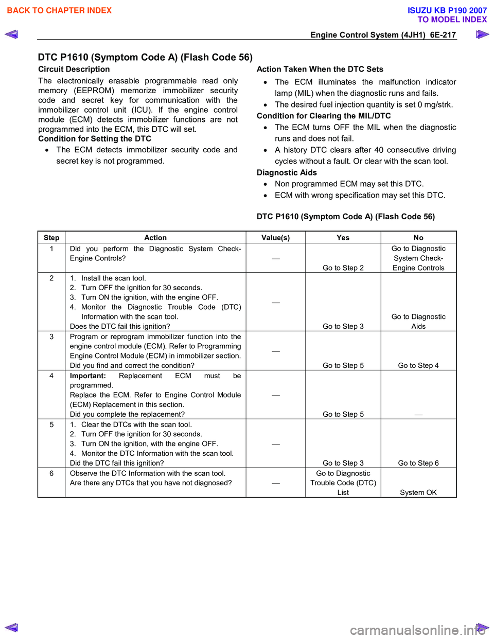
DTC P1610 (Symptom Code A) (Flash Code 56)
Circuit Description
The electronically erasable programmable read onl
y
memory (EEPROM) memorize immobilizer securit
y
code and secret key for communication with the
immobilizer control unit (ICU). If the engine control
module (ECM) detects immobilizer functions are not
programmed into the ECM, this DTC will set.
Condition for Setting the DTC
• The ECM detects immobilizer security code and
secret key is not programmed.
Action Taken When the DTC Sets
• The ECM illuminates the malfunction indicato
r
lamp (MIL) when the diagnostic runs and fails.
• The desired fuel injection quantity is set 0 mg/strk.
Condition for Clearing the MIL/DTC • The ECM turns OFF the MIL when the diagnostic
runs and does not fail.
• A history DTC clears after 40 consecutive driving
cycles without a fault. Or clear with the scan tool.
Diagnostic Aids • Non programmed ECM may set this DTC.
• ECM with wrong specification may set this DTC.
DTC P1610 (Symptom Code A) (Flash Code 56)
Step Action Value(s) Yes No
1 Did you perform the Diagnostic System Check-
Engine Controls?
Go to Step 2 Go to Diagnostic
System Check-
Engine Controls
2 1. Install the scan tool. 2. Turn OFF the ignition for 30 seconds.
3. Turn ON the ignition, with the engine OFF.
4. Monitor the Diagnostic Trouble Code (DTC) Information with the scan tool.
Does the DTC fail this ignition?
Go to Step 3 Go to Diagnostic
Aids
3 Program or reprogram immobilizer function into the engine control module (ECM). Refer to Programming
Engine Control Module (ECM) in immobilizer section.
Did you find and correct the condition?
Go to Step 5 Go to Step 4
4 Important: Replacement ECM must be
programmed.
Replace the ECM. Refer to Engine Control Module
(ECM) Replacement in this section.
Did you complete the replacement?
Go to Step 5
5 1. Clear the DTCs with the scan tool.
2. Turn OFF the ignition for 30 seconds.
3. Turn ON the ignition, with the engine OFF.
4. Monitor the DTC Information with the scan tool.
Did the DTC fail this ignition?
Go to Step 3 Go to Step 6
6 Observe the DTC Information with the scan tool. Are there any DTCs that you have not diagnosed? Go to Diagnostic
Trouble Code (DTC) List System OK
BACK TO CHAPTER INDEX
TO MODEL INDEX
ISUZU KB P190 2007
Page 1252 of 6020
6E-218 Engine Control System (4JH1)
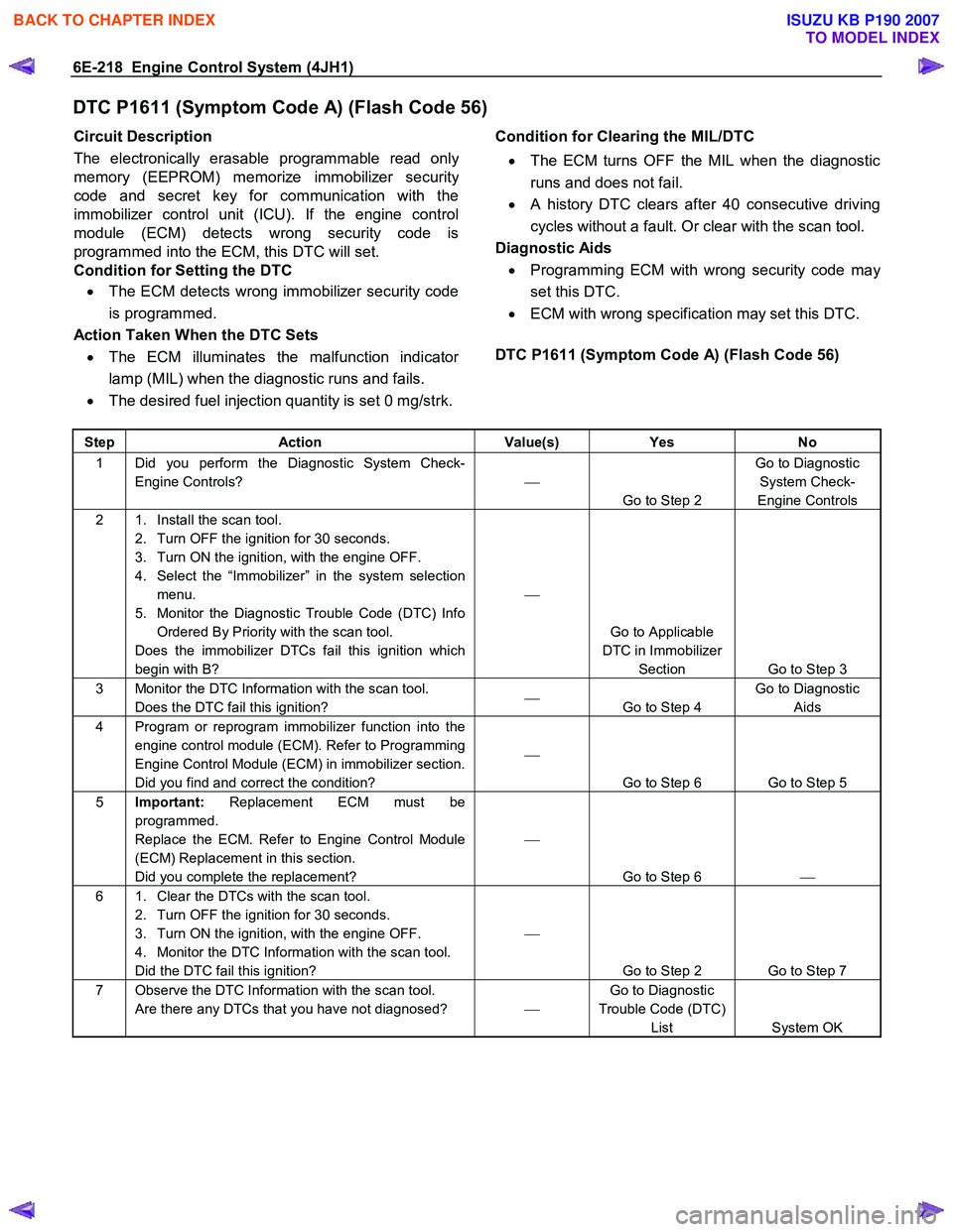
DTC P1611 (Symptom Code A) (Flash Code 56)
Circuit Description
The electronically erasable programmable read onl
y
memory (EEPROM) memorize immobilizer securit
y
code and secret key for communication with the
immobilizer control unit (ICU). If the engine control
module (ECM) detects wrong security code is
programmed into the ECM, this DTC will set.
Condition for Setting the DTC
• The ECM detects wrong immobilizer security code
is programmed.
Action Taken When the DTC Sets • The ECM illuminates the malfunction indicato
r
lamp (MIL) when the diagnostic runs and fails.
• The desired fuel injection quantity is set 0 mg/strk.
Condition for Clearing the MIL/DTC
• The ECM turns OFF the MIL when the diagnostic
runs and does not fail.
• A history DTC clears after 40 consecutive driving
cycles without a fault. Or clear with the scan tool.
Diagnostic Aids • Programming ECM with wrong security code ma
y
set this DTC.
• ECM with wrong specification may set this DTC.
DTC P1611 (Symptom Code A) (Flash Code 56)
Step Action Value(s) Yes No
1 Did you perform the Diagnostic System Check-
Engine Controls?
Go to Step 2 Go to Diagnostic
System Check-
Engine Controls
2 1. Install the scan tool. 2. Turn OFF the ignition for 30 seconds.
3. Turn ON the ignition, with the engine OFF.
4. Select the “Immobilizer” in the system selection menu.
5. Monitor the Diagnostic Trouble Code (DTC) Info Ordered By Priority with the scan tool.
Does the immobilizer DTCs fail this ignition which
begin with B?
Go to Applicable
DTC in Immobilizer Section Go to Step 3
3 Monitor the DTC Information with the scan tool. Does the DTC fail this ignition?
Go to Step 4 Go to Diagnostic
Aids
4 Program or reprogram immobilizer function into the engine control module (ECM). Refer to Programming
Engine Control Module (ECM) in immobilizer section.
Did you find and correct the condition?
Go to Step 6 Go to Step 5
5 Important: Replacement ECM must be
programmed.
Replace the ECM. Refer to Engine Control Module
(ECM) Replacement in this section.
Did you complete the replacement?
Go to Step 6
6 1. Clear the DTCs with the scan tool.
2. Turn OFF the ignition for 30 seconds.
3. Turn ON the ignition, with the engine OFF.
4. Monitor the DTC Information with the scan tool.
Did the DTC fail this ignition?
Go to Step 2 Go to Step 7
7 Observe the DTC Information with the scan tool. Are there any DTCs that you have not diagnosed? Go to Diagnostic
Trouble Code (DTC) List System OK
BACK TO CHAPTER INDEX
TO MODEL INDEX
ISUZU KB P190 2007
Page 1310 of 6020
6E-276 Engine Control System (4JH1)
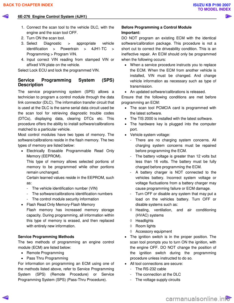
1. Connect the scan tool to the vehicle DLC, with theengine and the scan tool OFF.
2. Turn ON the scan tool.
3. Select Diagnostic > appropriate vehicle identification > Powertrain > 4JH1-TC >
Programming > Program VIN.
4. Input correct VIN reading from stamped VIN o
r
affixed VIN plate on the vehicle.
Select Lock ECU and lock the programmed VIN.
Service Programming System (SPS)
Description
The service programming system (SPS) allows a
technician to program a control module through the data
link connector (DLC). The information transfer circuit that
is used at the DLC is the same serial data circuit used be
the scan tool for retrieving diagnostic trouble codes
(DTCs), displaying data, clearing DTCs etc. This
procedure offers the ability to install software/calibrations
matched to a particular vehicle.
Most control modules have two types of memory. The
software/calibrations reside in the flash memory. The two
types of memory are listed below: • Electrically Erasable Programmable Read Onl
y
Memory (EEPROM).
This type of memory allows selected portions o
f
memory to be programmed while other portions
remain unchanged.
Certain learned values reside in the EEPROM, such as:
- The vehicle identification number (VIN)
- The software/calibrations identification numbers
- The control module security information
• Flash Read Only Memory-Flash Memory
Flash memory has increased memory storage capacity. During programming, all information within
this type of memory is erased, and then replaced
with entirely new information.
Service Programming Methods
The two methods of programming an engine control
module (ECM) are listed below: • Remote Programming
• Pass Thru Programming
For information on programming an ECM using one o
f
the methods listed above, refer to Service Programming
System (SPS) (Remote Procedure) or Service
Programming System (SPS) (Pass-Thru Procedure).
Before Programming a Control Module
Important:
DO NOT program an existing ECM with the identical
software/calibration package. This procedure is not a
short cut to correct the driveability condition. This is an
ineffective repair. An ECM should only be programmed
when the following occurs: • W hen a service procedure instructs you to replace
the ECM. W hen the ECM from another vehicle is
installed, VIN must be changed. And change
vehicle information as necessary such as type o
f
transmission.
• An updated software/calibrations is released.
Ensure that the following conditions are met before
programming an ECM: • The scan tool PCMCIA card is programmed with
the latest software.
• The TIS 2000 is installed with the latest software.
• The hardware key is plugged into the compute
r
port.
• Vehicle system voltage:
- There are no charging system concerns. All charging system concerns must be repaired
before programming the ECM.
- The battery voltage is greater than 12 volts bu
t
less than 16 volts. The battery must be fully
charged before programming the ECM.
-
A battery charger is NOT connected to the
vehicles battery. Incorrect system voltage o
r
voltage fluctuations from a battery charger may
cause programming failure or ECM damage.
- Turn OFF or disable any system that may put a load on the vehicles battery. Turn OFF o
r
disable systems such as:
◊ Heating, ventilation, and air conditioning
(HVAC) systems
◊ Headlights
◊ Room lights
◊ Accessory equipment
• The ignition switch is in the proper position. The
scan tool prompts you to turn ON the ignition, with
the engine OFF. DO NOT change the position o
f
the ignition switch during the programming
procedure unless instructed to do so.
• All tool connections are secure:
- The RS-232 cable
- The connection at the DLC
- The voltage supply circuits
BACK TO CHAPTER INDEX
TO MODEL INDEX
ISUZU KB P190 2007
Page 1558 of 6020
FUEL SYSTEM (4JK1/4JJ1) 6C-17
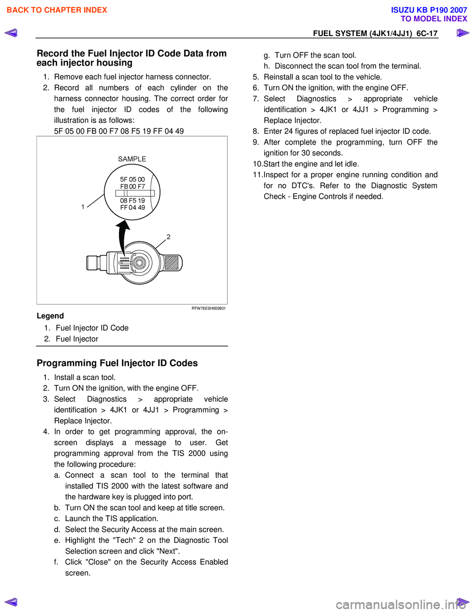
Record the Fuel Injector ID Code Data from
each injector housing
1. Remove each fuel injector harness connector.
2. Record all numbers of each cylinder on the harness connector housing. The correct order fo
r
the fuel injector ID codes of the following
illustration is as follows:
5F 05 00 FB 00 F7 08 F5 19 FF 04 49
RTW 76ESH002601
Legend
1. Fuel Injector ID Code
2. Fuel Injector
Programming Fuel Injector ID Codes
1. Install a scan tool.
2. Turn ON the ignition, with the engine OFF.
3. Select Diagnostics > appropriate vehicle identification > 4JK1 or 4JJ1 > Programming >
Replace Injector.
4. In order to get programming approval, the on- screen displays a message to user. Get
programming approval from the TIS 2000 using
the following procedure:
a. Connect a scan tool to the terminal that installed TIS 2000 with the latest software and
the hardware key is plugged into port.
b. Turn ON the scan tool and keep at title screen.
c. Launch the TIS application.
d. Select the Security Access at the main screen.
e. Highlight the "Tech" 2 on the Diagnostic Tool Selection screen and click "Next".
f. Click "Close" on the Security Access Enabled screen.
g. Turn OFF the scan tool.
h. Disconnect the scan tool from the terminal.
5. Reinstall a scan tool to the vehicle.
6. Turn ON the ignition, with the engine OFF.
7. Select Diagnostics > appropriate vehicle identification > 4JK1 or 4JJ1 > Programming >
Replace Injector.
8. Enter 24 figures of replaced fuel injector ID code.
9.
After complete the programming, turn OFF the
ignition for 30 seconds.
10.Start the engine and let idle.
11.Inspect for a proper engine running condition and for no DTC's. Refer to the Diagnostic System
Check - Engine Controls if needed.
BACK TO CHAPTER INDEX
TO MODEL INDEX
ISUZU KB P190 2007
Page 1662 of 6020
ENGINE CONTROL SYSTEM (4JK1/4JJ1) 6E-45
Diagnostic System Check - Engine Controls
Description
The Diagnostic System Check - Engine Controls is an
organized approach to identifying a condition that is
created by a malfunction in the electronic engine
control system. The Diagnostic System Check must be
the starting point for any driveability concern. The
Diagnostic System Check directs the service technician
to the next logical step in order to diagnose the
concern. Understanding and correctly using the
diagnostic table reduces diagnostic time, and prevents
the replacement of good parts.
Test Description
The numbers below refer to the step numbers on the
diagnostic table.
2. Lack of communication may be because of a partial
or a total malfunction of the serial data circuit.
7. The presence of DTCs which begin with U, indicate
that some other module is not communicating.
10. If there are other modules with DTCs set, refer to
the DTC list. The DTC list directs you to the appropriate
diagnostic procedure. If the control module stores
multiple DTCs, diagnose the DTCs in the following
order:
• Component level DTCs, such as sensor DTCs, solenoid DTCs, actuator DTCs, and relay DTCs.
Diagnose the multiple DTCs within this category in
numerical order. Begin with the lowest numbered
DTC, unless the diagnostic table directs you
otherwise. Diagnostic System Check Engine Controls
Important:
• DO NOT perform this diagnostic if there is not a driveability concern, unless another procedure
directs you to this diagnostic.
• Before you proceed with diagnosis, search for applicable service bulletins.
• Unless a diagnostic procedure instructs you, DO NOT clear the DTCs.
• If there is a condition with the starting system, refer to the starting system section in the engine
mechanical.
• Ensure the battery has a full charge.
• Ensure the battery cables (+) (-) are clean and tight.
• Ensure the ECM grounds are clean, tight, and in the correct location.
• Ensure the ECM harness connectors are clean and correctly connected. DO NOT attempt to
crank the engine with ECM harness connectors
disconnect.
• Ensure the ECM terminals are clean and correctly mating.
• Ensure the fuel injector ID code data is correctly programmed in to the ECM.
• Ensure the immobilizer security information is correctly programmed into the ECM and
immobilizer control unit (ICU).
• If there are fuel system DTC’s (P0087, P0088, P0089, P0093, P1093 or P1094), diagnose sensor
DTCs, solenoid DTCs, actuator DTCs and relay
DTCs first.
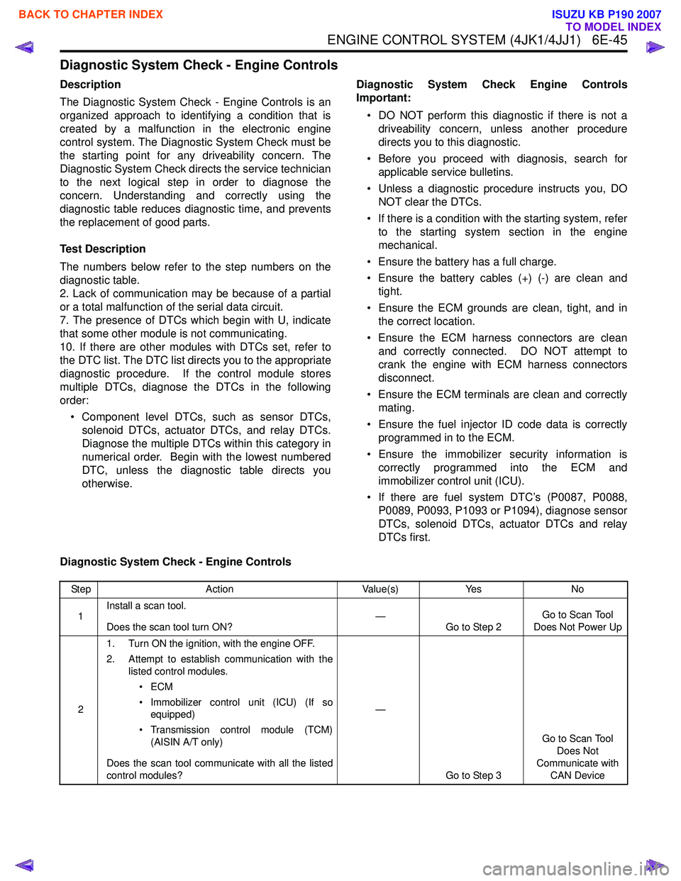
Diagnostic System Check - Engine Controls
Step Action Value(s)Yes No
1 Install a scan tool.
Does the scan tool turn ON? —
Go to Step 2 Go to Scan Tool
Does Not Power Up
2 1. Turn ON the ignition, with the engine OFF.
2. Attempt to establish communication with the listed control modules.
•ECM
• Immobilizer control unit (ICU) (If so equipped)
• Transmission control module (TCM) (AISIN A/T only)
Does the scan tool communicate with all the listed
control modules? —
Go to Step 3 Go to Scan Tool
Does Not
Communicate with CAN Device
BACK TO CHAPTER INDEX
TO MODEL INDEX
ISUZU KB P190 2007
Page 1667 of 6020
6E-50 ENGINE CONTROL SYSTEM (4JK1/4JJ1)
Scan Tool Data Definitions
This information will assist in emission or driveability
problems. The displays can be viewed while the vehicle
is being driven. Always perform the Diagnostic System
Check - Engine Controls first. The Diagnostic System
Check will confirm proper system operation.
Engine Speed
This parameter displays the rotational speed of the
crankshaft as calculated by the ECM based on inputs
from the crankshaft position (CKP) sensor or camshaft
position (CMP) sensor.
Desired Idle Speed
This parameter displays the idle speed requested by
the ECM. The ECM will change desired idle speed
based on engine coolant temperature and other inputs.
Calculate Engine Load
This parameter displays the engine load in percent
based on inputs to the ECM from various engine
sensors. The scan tool will display a lower percentage
when the engine is at idle with little or no load. The
scan tool will display a higher percentage when the
engine is running at high engine speed under a heavy
load.
Coolant Temperature
This parameter displays the temperature of the engine
coolant as calculated by the ECM using the signal from
the engine coolant temperature (ECT) sensor. The
scan tool will display a low temperature when the ECT
sensor signal voltage is high, and a high temperature
when the ECT sensor signal voltage is low.
Engine Coolant Temperature Sensor
This parameter displays the voltage signal sent to the
ECM from the engine coolant temperature (ECT)
sensor. ECT sensor is a range of value indicating a low
voltage when the temperature is high, and a high
voltage when the temperature is low.
Intake Air Temperature
This parameter displays the temperature of the intake
air as calculated by the ECM using the signal from the
intake air temperature (IAT) sensor. The scan tool will
display a low temperature when the IAT sensor signal
voltage is high, and a high temperature when the IAT
sensor signal voltage is low. Intake Air Temperature Sensor
This parameter displays the voltage signal sent to the
ECM from the intake air temperature (IAT) sensor. IAT
sensor is a range of value indicating a low voltage
when the temperature is high, and a high voltage when
the temperature is low.
Fuel Temperature
This parameter displays the temperature of the fuel as
calculated by the ECM using the signal from the fuel
temperature (FT) sensor. The scan tool will display a
low temperature when the FT sensor signal voltage is
high, and a high temperature when the FT sensor
signal voltage is low.
Fuel Temperature Sensor
This parameter displays the voltage signal sent to the
ECM from the fuel temperature (FT) sensor. FT sensor
is a range of value indicating a low voltage when the
temperature is high, and a high voltage when the
temperature is low.
MAF (Mass Air Flow)
This parameter displays the air flow into the engine as
calculated by the ECM based on the mass air flow
(MAF) sensor input. The scan tool will display a high
value at higher engine speeds, and a low value at lower
engine speed.
MAF Sensor (Mass Air Flow)
This parameter displays the voltage signal sent to the
ECM from the mass air flow (MAF) sensor. MAF sensor
is a range of value indicating a low voltage at lower
engine speed, and a high voltage at a higher engine
speeds.
Barometric Pressure
This parameter displays the barometric pressure
(BARO) as calculated by the ECM using the signal from
the BARO sensor. The scan tool will display a low
barometric pressure in high altitude area.
Barometric Pressure Sensor
This parameter displays the voltage signal sent to the
ECM from the barometric pressure (BARO) sensor.
BARO sensor is a range of value indicating a low
voltage in high altitude area, and a middle voltage in
sea level.
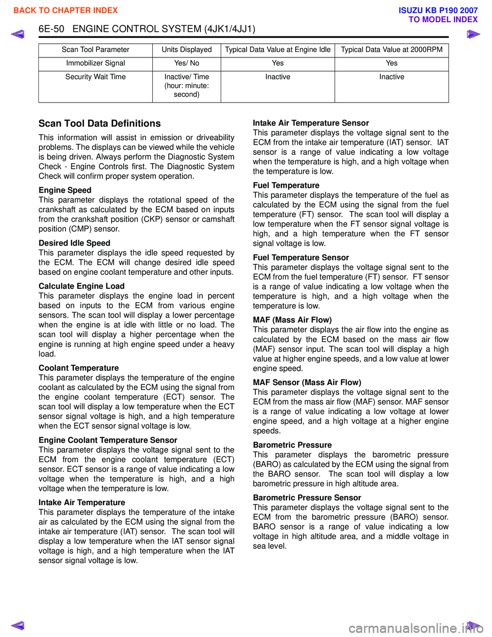
Immobilizer Signal Yes/ NoYes Yes
Security Wait Time Inactive/ Time
(hour: minute: second) Inactive
Inactive
Scan Tool Parameter Units Displayed Typical Data Value at Engine Idle Typical Data Value at 2000RPM
BACK TO CHAPTER INDEX
TO MODEL INDEX
ISUZU KB P190 2007