2007 ISUZU KB P190 EGR
[x] Cancel search: EGRPage 3298 of 6020
Engine Management – V6 – Diagnostics Page 6C1-2–20
• Ensure the resistance between the ECM housing and the battery negative cable is less than 0.5 Ω.
• Check the ECM bracket fasteners for correct torque value.
• Check all engine management related components for correct installation.
• Inspect the vacuum hoses for splits, kinks, oil contamination and proper connections, refer to the vehicle emission
control information label. Check the hoses thoroughly for any type of leak or restriction.
• Inspect the air intake ducts for being collapsed, split or for having damaged areas.
• Inspect for air leaks at the throttle body mounting area, mass air flow (MAF) sensor, intake manifold and intake
manifold sealing surfaces.
• Check for wiring harness routing that may be positioned too close to a high voltage or high current device such as
the following:
− Secondary ignition components, and
− Motors and generators.
NOTE
High voltage or high current devices may induce
electrical noise on a circuit, which can interfere
with normal circuit operation.
4.4 Diagnostic System Check
Description
The engine management diagnostic procedure is organised in a logical structure that begins with the Diagnostic System
Check. The Diagnostic System Check directs the diagnostic procedure to the logical steps necessary to diagnose an
engine driveability fault condition.
Test Description
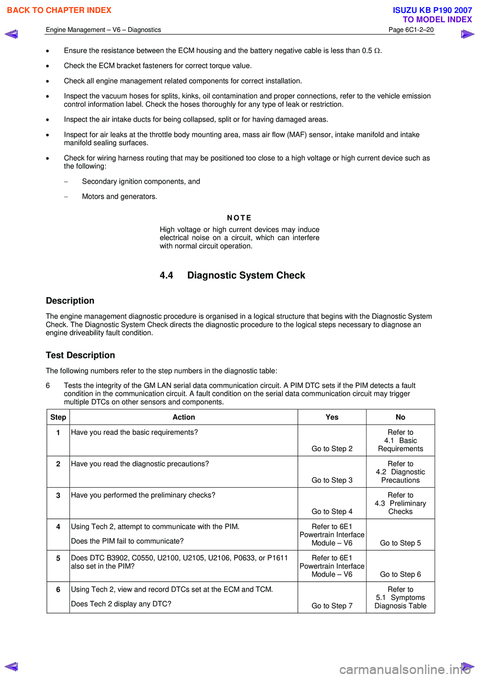
The following numbers refer to the step numbers in the diagnostic table:
6 Tests the integrity of the GM LAN serial data communication circuit. A PIM DTC sets if the PIM detects a fault condition in the communication circuit. A fault condition on the serial data communication circuit may trigger
multiple DTCs on other sensors and components.
Step Action Yes No
1 Have you read the basic requirements?
Go to Step 2 Refer to
4.1 Basic
Requirements
2 Have you read the diagnostic precautions?
Go to Step 3 Refer to
4.2 Diagnostic Precautions
3 Have you performed the preliminary checks?
Go to Step 4 Refer to
4.3 Preliminary Checks
4 Using Tech 2, attempt to communicate with the PIM.
Does the PIM fail to communicate? Refer to 6E1
Powertrain Interface Module – V6 Go to Step 5
5 Does DTC B3902, C0550, U2100, U2105, U2106, P0633, or P1611
also set in the PIM? Refer to 6E1
Powertrain Interface Module – V6 Go to Step 6
6 Using Tech 2, view and record DTCs set at the ECM and TCM.
Does Tech 2 display any DTC? Go to Step 7 Refer to
5.1 Symptoms
Diagnosis Table
BACK TO CHAPTER INDEX
TO MODEL INDEX
ISUZU KB P190 2007
Page 3351 of 6020
Engine Management – V6 – Diagnostics Page 6C1-2–73
• Increased temperature in the intake air decreases the resistance value of the IAT sensor. This increases the IAT
sensor pull-down rate to ground. Therefore, the higher the intake air temperature, the lower the signal voltage
output of the IAT sensor.
• Decreased temperature in the intake air increases the resistance value of the IAT sensor. This reduces the IAT
sensor pull-down rate to ground. Therefore, the lower the intake air temperature, the higher the signal voltage
output of the IAT sensor.
An IAT sensor circuit DTC sets if the ECM detects the intake air temperature is outside the specified range.
Conditions for Running the DTC
Runs continuously once the following conditions are met:
• The engine is running for longer than 3.0 minutes.
• The engine is idling for longer than 10.0 seconds
Conditions for Setting the DTC
DTC P0112
The ECM detects the intake air temperature is greater than 132 °C for longer than 3.0 seconds.
DTC P0113
The ECM detects the intake air temperature is less than - 38 °C for longer than 3.0 seconds.
Conditions for Clearing the DTC
The IAT sensor DTCs are Type B DTCs. Refer to 1.4 Diagnostic Trouble Codes in this Section, for action taken when
a Type B DTC sets and conditions for clearing Type B DTC.
Additional Information
• Refer to 6C1-1 Engine Management – V6 – General Information for details of the IAT Sensor operation.
• For an intermittent fault condition, refer to 5.2 Intermittent Fault Conditions in this Section.
• Test the IAT sensor using the IAT Temperature vs. Resistance in 6C1-3 Engine Management – V6 – Service
Operations. If the engine has sat overnight, the IAT sensor should display within 3 °C of the ECT sensor values.
• Since fault condition in a wiring connector may trigger DTCs, always test the connectors related to this diagnostic
procedure for shorted terminals or poor wiring connection before replacing any component. Refer to 8A Electrical -
Body and Chassis for information on electrical fault diagnosis.
• To assist diagnosis, refer to 3 W iring Diagrams and Connector Charts in this Section, for the system wiring
diagram and connector charts.
Test Description
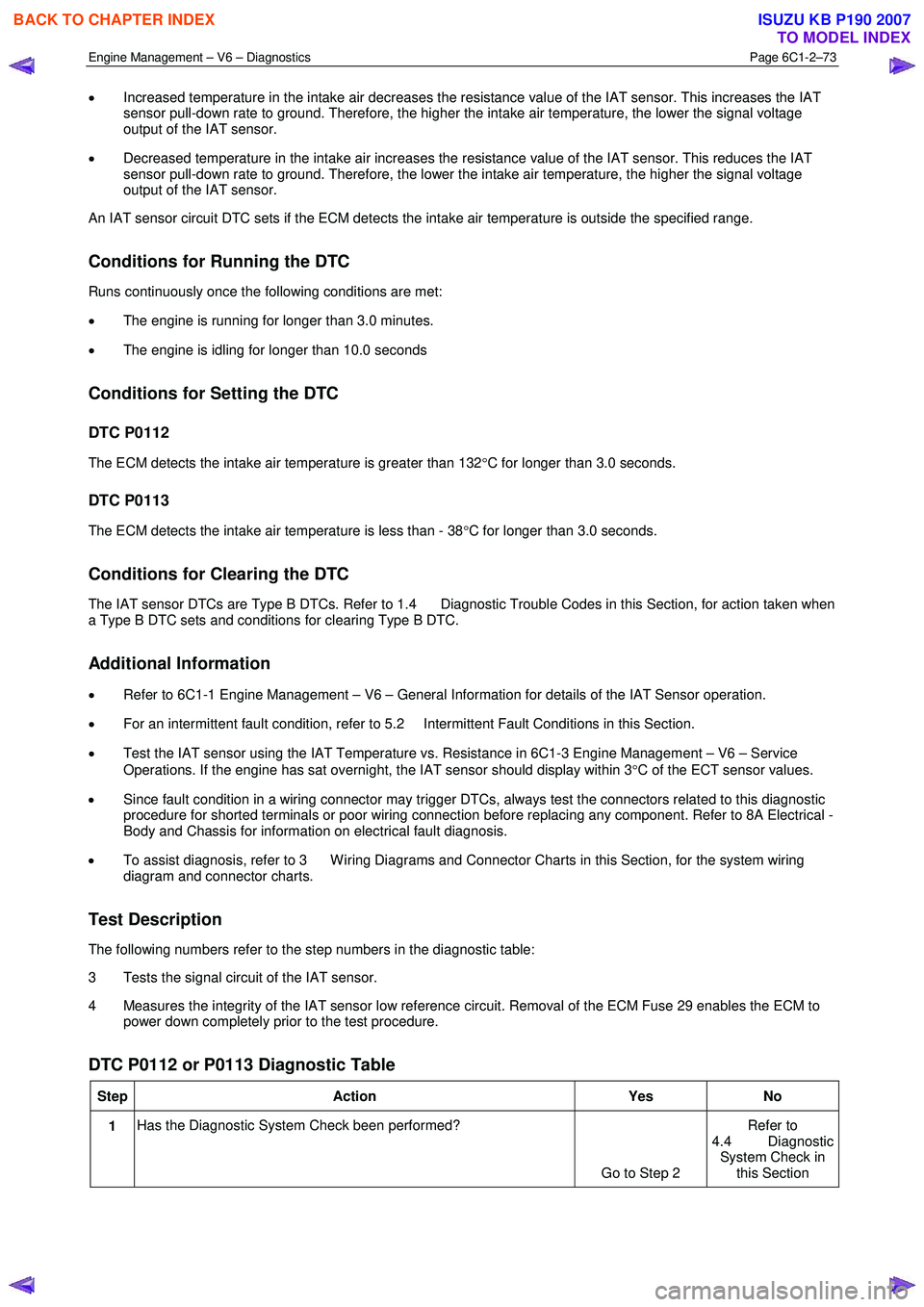
The following numbers refer to the step numbers in the diagnostic table:
3 Tests the signal circuit of the IAT sensor.
4 Measures the integrity of the IAT sensor low reference circuit. Removal of the ECM Fuse 29 enables the ECM to power down completely prior to the test procedure.
DTC P0112 or P0113 Diagnostic Table
Step Action Yes No
1 Has the Diagnostic System Check been performed?
Go to Step 2 Refer to
4.4 Diagnostic System Check in this Section
BACK TO CHAPTER INDEX
TO MODEL INDEX
ISUZU KB P190 2007
Page 3358 of 6020
Engine Management – V6 – Diagnostics Page 6C1-2–80
Test Description
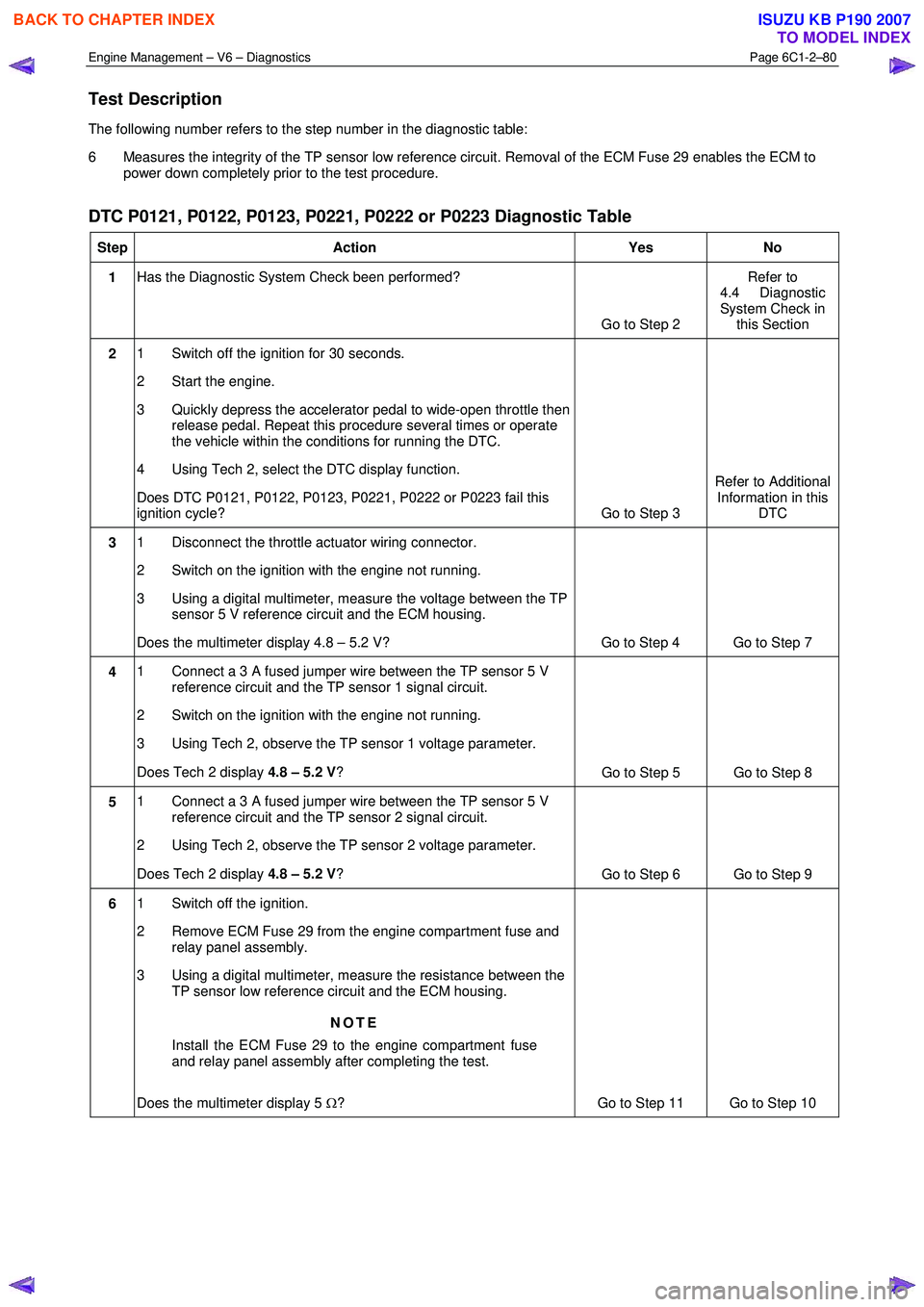
The following number refers to the step number in the diagnostic table:
6 Measures the integrity of the TP sensor low reference circuit. Removal of the ECM Fuse 29 enables the ECM to power down completely prior to the test procedure.
DTC P0121, P0122, P0123, P0221, P0222 or P0223 Diagnostic Table
Step Action Yes No
1 Has the Diagnostic System Check been performed?
Go to Step 2 Refer to
4.4 Diagnostic
System Check in this Section
2 1 Switch off the ignition for 30 seconds.
2 Start the engine.
3 Quickly depress the accelerator pedal to wide-open throttle then release pedal. Repeat this procedure several times or operate
the vehicle within the conditions for running the DTC.
4 Using Tech 2, select the DTC display function.
Does DTC P0121, P0122, P0123, P0221, P0222 or P0223 fail this
ignition cycle? Go to Step 3 Refer to Additional
Information in this DTC
3 1 Disconnect the throttle actuator wiring connector.
2 Switch on the ignition with the engine not running.
3 Using a digital multimeter, measure the voltage between the TP sensor 5 V reference circuit and the ECM housing.
Does the multimeter display 4.8 – 5.2 V? Go to Step 4 Go to Step 7
4 1 Connect a 3 A fused jumper wire between the TP sensor 5 V
reference circuit and the TP sensor 1 signal circuit.
2 Switch on the ignition with the engine not running.
3 Using Tech 2, observe the TP sensor 1 voltage parameter.
Does Tech 2 display 4.8 – 5.2 V?
Go to Step 5 Go to Step 8
5 1 Connect a 3 A fused jumper wire between the TP sensor 5 V
reference circuit and the TP sensor 2 signal circuit.
2 Using Tech 2, observe the TP sensor 2 voltage parameter.
Does Tech 2 display 4.8 – 5.2 V?
Go to Step 6 Go to Step 9
6 1 Switch off the ignition.
2 Remove ECM Fuse 29 from the engine compartment fuse and relay panel assembly.
3 Using a digital multimeter, measure the resistance between the TP sensor low reference circuit and the ECM housing.
NOTE
Install the ECM Fuse 29 to the engine compartment fuse
and relay panel assembly after completing the test.
Does the multimeter display 5 Ω? Go to Step 11 Go to Step 10
BACK TO CHAPTER INDEX
TO MODEL INDEX
ISUZU KB P190 2007
Page 3374 of 6020
Engine Management – V6 – Diagnostics Page 6C1-2–96
• Since fault condition in a wiring connector may trigger DTCs, always test the connectors related to this diagnostic
procedure for shorted terminals or poor wiring connection before replacing any component. Refer to 8A Electrical -
Body and Chassis for information on electrical fault diagnosis.
• To assist diagnosis, refer to 3 W iring Diagrams and Connector Charts in this Section, for the system wiring
diagram and connector charts.
Test Description
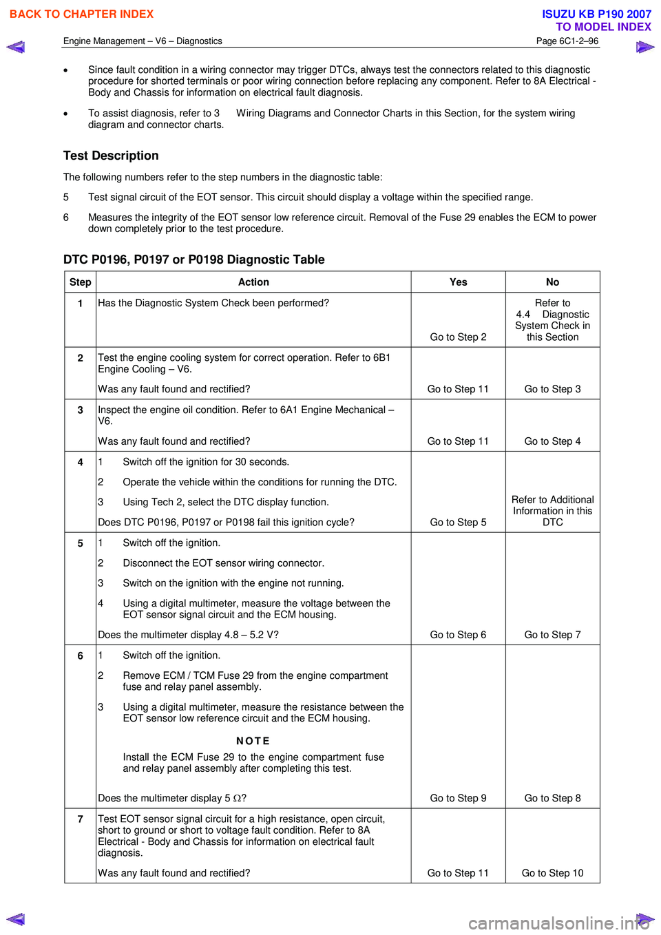
The following numbers refer to the step numbers in the diagnostic table:
5 Test signal circuit of the EOT sensor. This circuit should display a voltage within the specified range.
6 Measures the integrity of the EOT sensor low reference circuit. Removal of the Fuse 29 enables the ECM to power down completely prior to the test procedure.
DTC P0196, P0197 or P0198 Diagnostic Table
Step Action Yes No
1 Has the Diagnostic System Check been performed?
Go to Step 2 Refer to
4.4 Diagnostic
System Check in this Section
2 Test the engine cooling system for correct operation. Refer to 6B1
Engine Cooling – V6.
W as any fault found and rectified? Go to Step 11 Go to Step 3
3 Inspect the engine oil condition. Refer to 6A1 Engine Mechanical –
V6.
W as any fault found and rectified? Go to Step 11 Go to Step 4
4 1 Switch off the ignition for 30 seconds.
2 Operate the vehicle within the conditions for running the DTC.
3 Using Tech 2, select the DTC display function.
Does DTC P0196, P0197 or P0198 fail this ignition cycle? Go to Step 5 Refer to Additional
Information in this DTC
5 1 Switch off the ignition.
2 Disconnect the EOT sensor wiring connector.
3 Switch on the ignition with the engine not running.
4 Using a digital multimeter, measure the voltage between the EOT sensor signal circuit and the ECM housing.
Does the multimeter display 4.8 – 5.2 V? Go to Step 6 Go to Step 7
6 1 Switch off the ignition.
2 Remove ECM / TCM Fuse 29 from the engine compartment fuse and relay panel assembly.
3 Using a digital multimeter, measure the resistance between the EOT sensor low reference circuit and the ECM housing.
NOTE
Install the ECM Fuse 29 to the engine compartment fuse
and relay panel assembly after completing this test.
Does the multimeter display 5 Ω? Go to Step 9 Go to Step 8
7 Test EOT sensor signal circuit for a high resistance, open circuit,
short to ground or short to voltage fault condition. Refer to 8A
Electrical - Body and Chassis for information on electrical fault
diagnosis.
W as any fault found and rectified? Go to Step 11 Go to Step 10
BACK TO CHAPTER INDEX
TO MODEL INDEX
ISUZU KB P190 2007
Page 3394 of 6020
Engine Management – V6 – Diagnostics Page 6C1-2–116
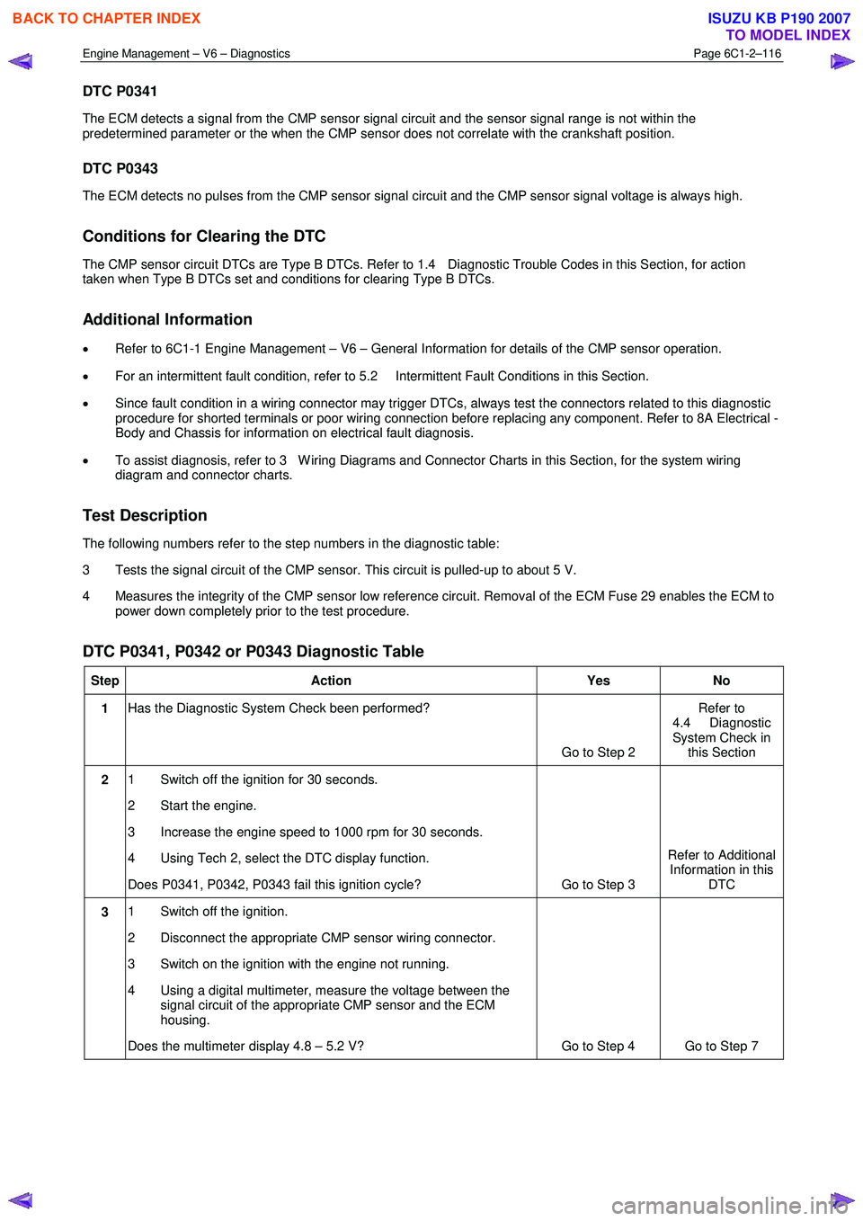
DTC P0341
The ECM detects a signal from the CMP sensor signal circuit and the sensor signal range is not within the
predetermined parameter or the when the CMP sensor does not correlate with the crankshaft position.
DTC P0343
The ECM detects no pulses from the CMP sensor signal circuit and the CMP sensor signal voltage is always high.
Conditions for Clearing the DTC
The CMP sensor circuit DTCs are Type B DTCs. Refer to 1.4 Diagnostic Trouble Codes in this Section, for action
taken when Type B DTCs set and conditions for clearing Type B DTCs.
Additional Information
• Refer to 6C1-1 Engine Management – V6 – General Information for details of the CMP sensor operation.
• For an intermittent fault condition, refer to 5.2 Intermittent Fault Conditions in this Section.
• Since fault condition in a wiring connector may trigger DTCs, always test the connectors related to this diagnostic
procedure for shorted terminals or poor wiring connection before replacing any component. Refer to 8A Electrical -
Body and Chassis for information on electrical fault diagnosis.
• To assist diagnosis, refer to 3 W iring Diagrams and Connector Charts in this Section, for the system wiring
diagram and connector charts.
Test Description
The following numbers refer to the step numbers in the diagnostic table:
3 Tests the signal circuit of the CMP sensor. This circuit is pulled-up to about 5 V.
4 Measures the integrity of the CMP sensor low reference circuit. Removal of the ECM Fuse 29 enables the ECM to power down completely prior to the test procedure.
DTC P0341, P0342 or P0343 Diagnostic Table
Step Action Yes No
1 Has the Diagnostic System Check been performed?
Go to Step 2 Refer to
4.4 Diagnostic
System Check in this Section
2 1 Switch off the ignition for 30 seconds.
2 Start the engine.
3 Increase the engine speed to 1000 rpm for 30 seconds.
4 Using Tech 2, select the DTC display function.
Does P0341, P0342, P0343 fail this ignition cycle? Go to Step 3 Refer to Additional
Information in this DTC
3 1 Switch off the ignition.
2 Disconnect the appropriate CMP sensor wiring connector.
3 Switch on the ignition with the engine not running.
4 Using a digital multimeter, measure the voltage between the signal circuit of the appropriate CMP sensor and the ECM
housing.
Does the multimeter display 4.8 – 5.2 V? Go to Step 4 Go to Step 7
BACK TO CHAPTER INDEX
TO MODEL INDEX
ISUZU KB P190 2007
Page 3400 of 6020
Engine Management – V6 – Diagnostics Page 6C1-2–122
P0158, P0159, P0160, P0161, P0221, P0222, P0223, P0300, P0301-P0306, P0443, P0458, P0459, P0496,
P167A, P167B, P2096, P2097, P2098, P2099, P2100, P2101, P2107, P2119, P2122, P2123, P2127, P2128,
P2138, P2176, P2177, P2178, P2179, P2180, P2187, P2188, P2189, P2190, P2195, P2196, P2197, P2198,
P2232, P2235, P2237, P2240, P2243, P2247, P2251, P2254, P2270, P2271, P2272, P2273, P2297, P2298,
P2626, and P2629.
• The engine speed is 1,040 – 3,000 rpm.
• The air flow into the engine is between 7.0 – 16.0 g/s and not changing more than 3.0 g/s
• The engine intake air temperature (IAT) at engine start-up is more than –30° C.
• The engine is operating for more than 7 minutes.
• The engine is operating in Closed Loop.
• The calculated TW C temperature is between 500 – 750° C and steady.
• The above conditions exist for approximately 17 minutes.
• DTCs P0420 and P0430 run once a drive cycle. The ECM will attempt to run this diagnostic up to three times a
drive cycle.
Conditions for Setting the DTC
The ECM determines that the catalyst efficiency has degraded below a calibrated threshold for more than 4 seconds.
Action Taken When the DTC Sets
• The control module activates the malfunction indicator lamp (MIL) on the second consecutive ignition cycle that
the diagnostic runs and fails.
• The control module records the operating conditions at the time the diagnostic fails. The first time the diagnostic
fails, the control module stores this information in the Failure Records. If the diagnostic reports a failure on the
second consecutive ignition cycle, the control module records the operating conditions at the time of the failure.
The control module writes the operating conditions to the Freeze Frame and updates the Failure Records.
Conditions for Clearing the DTC
The EVAP Purge Solenoid Valve Control Circuit DTCs are Type B DTCs. Refer to 1.4 Diagnostic Trouble Codes in
this Section, for action taken when a Type B DTC sets and conditions for clearing Type B DTCs.
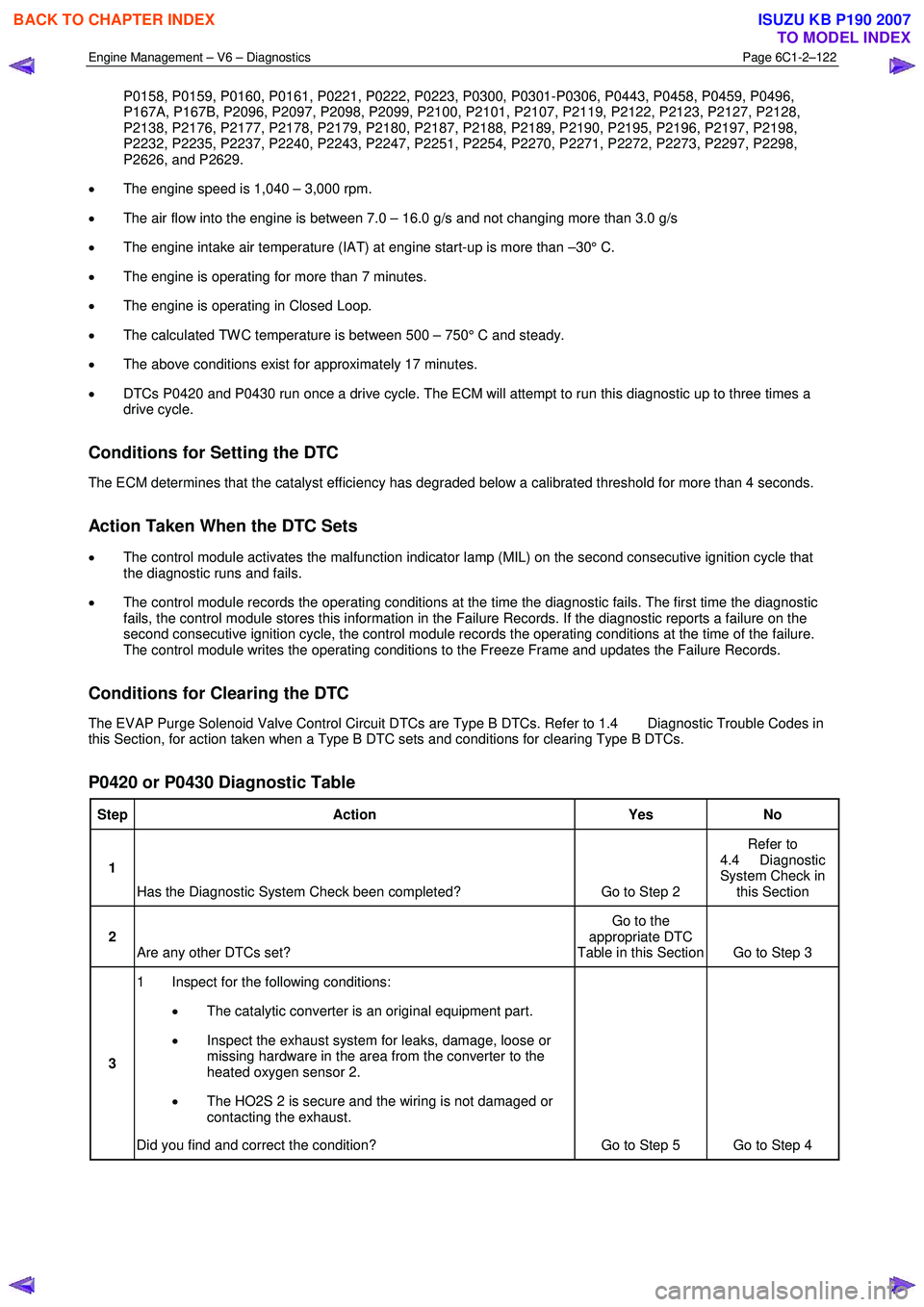
P0420 or P0430 Diagnostic Table
Step Action Yes No
1
Has the Diagnostic System Check been completed? Go to Step 2 Refer to
4.4 Diagnostic
System Check in this Section
2 Are any other DTCs set? Go to the
appropriate DTC
Table in this Section Go to Step 3
3 1 Inspect for the following conditions:
• The catalytic converter is an original equipment part.
• Inspect the exhaust system for leaks, damage, loose or
missing hardware in the area from the converter to the
heated oxygen sensor 2.
• The HO2S 2 is secure and the wiring is not damaged or
contacting the exhaust.
Did you find and correct the condition? Go to Step 5 Go to Step 4
BACK TO CHAPTER INDEX
TO MODEL INDEX
ISUZU KB P190 2007
Page 3415 of 6020
Engine Management – V6 – Diagnostics Page 6C1-2–137
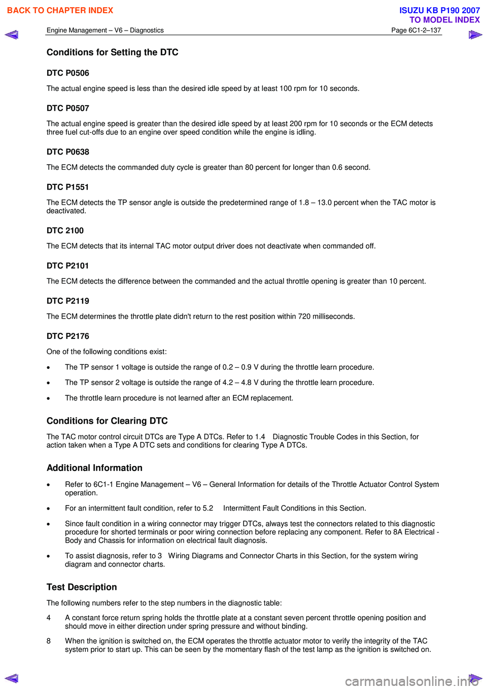
Conditions for Setting the DTC
DTC P0506
The actual engine speed is less than the desired idle speed by at least 100 rpm for 10 seconds.
DTC P0507
The actual engine speed is greater than the desired idle speed by at least 200 rpm for 10 seconds or the ECM detects
three fuel cut-offs due to an engine over speed condition while the engine is idling.
DTC P0638
The ECM detects the commanded duty cycle is greater than 80 percent for longer than 0.6 second.
DTC P1551
The ECM detects the TP sensor angle is outside the predetermined range of 1.8 – 13.0 percent when the TAC motor is
deactivated.
DTC 2100
The ECM detects that its internal TAC motor output driver does not deactivate when commanded off.
DTC P2101
The ECM detects the difference between the commanded and the actual throttle opening is greater than 10 percent.
DTC P2119
The ECM determines the throttle plate didn't return to the rest position within 720 milliseconds.
DTC P2176
One of the following conditions exist:
• The TP sensor 1 voltage is outside the range of 0.2 – 0.9 V during the throttle learn procedure.
• The TP sensor 2 voltage is outside the range of 4.2 – 4.8 V during the throttle learn procedure.
• The throttle learn procedure is not learned after an ECM replacement.
Conditions for Clearing DTC
The TAC motor control circuit DTCs are Type A DTCs. Refer to 1.4 Diagnostic Trouble Codes in this Section, for
action taken when a Type A DTC sets and conditions for clearing Type A DTCs.
Additional Information
• Refer to 6C1-1 Engine Management – V6 – General Information for details of the Throttle Actuator Control System
operation.
• For an intermittent fault condition, refer to 5.2 Intermittent Fault Conditions in this Section.
• Since fault condition in a wiring connector may trigger DTCs, always test the connectors related to this diagnostic
procedure for shorted terminals or poor wiring connection before replacing any component. Refer to 8A Electrical -
Body and Chassis for information on electrical fault diagnosis.
• To assist diagnosis, refer to 3 W iring Diagrams and Connector Charts in this Section, for the system wiring
diagram and connector charts.
Test Description
The following numbers refer to the step numbers in the diagnostic table:
4 A constant force return spring holds the throttle plate at a constant seven percent throttle opening position and should move in either direction under spring pressure and without binding.
8 W hen the ignition is switched on, the ECM operates the throttle actuator motor to verify the integrity of the TAC system prior to start up. This can be seen by the momentary flash of the test lamp as the ignition is switched on.
BACK TO CHAPTER INDEX
TO MODEL INDEX
ISUZU KB P190 2007
Page 3418 of 6020
Engine Management – V6 – Diagnostics Page 6C1-2–140
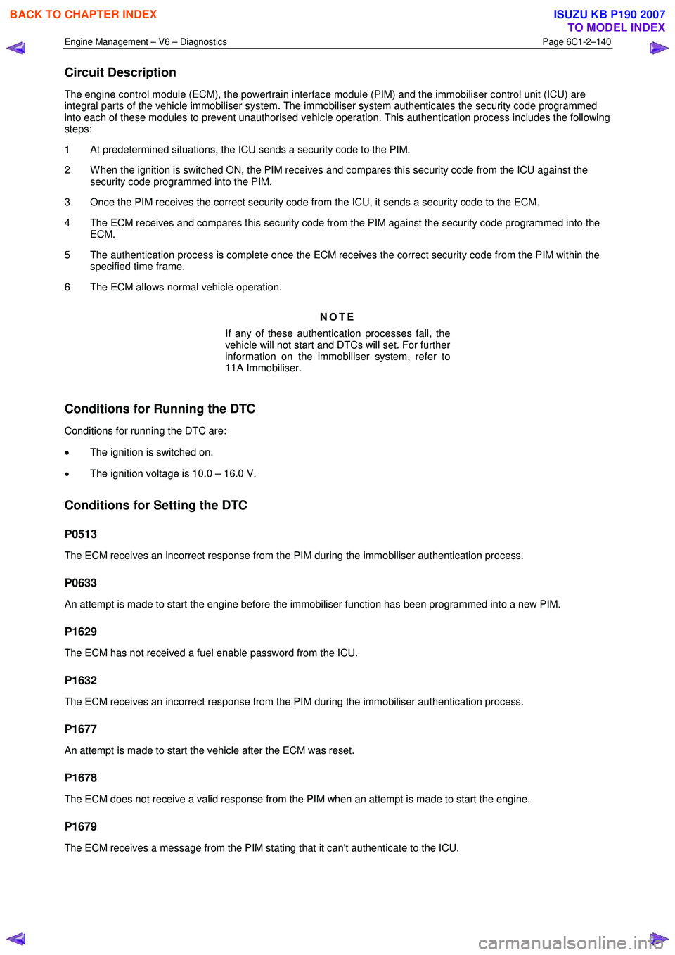
Circuit Description
The engine control module (ECM), the powertrain interface module (PIM) and the immobiliser control unit (ICU) are
integral parts of the vehicle immobiliser system. The immobiliser system authenticates the security code programmed
into each of these modules to prevent unauthorised vehicle operation. This authentication process includes the following
steps:
1 At predetermined situations, the ICU sends a security code to the PIM.
2 W hen the ignition is switched ON, the PIM receives and compares this security code from the ICU against the security code programmed into the PIM.
3 Once the PIM receives the correct security code from the ICU, it sends a security code to the ECM.
4 The ECM receives and compares this security code from the PIM against the security code programmed into the ECM.
5 The authentication process is complete once the ECM receives the correct security code from the PIM within the specified time frame.
6 The ECM allows normal vehicle operation.
NOTE
If any of these authentication processes fail, the
vehicle will not start and DTCs will set. For further
information on the immobiliser system, refer to
11A Immobiliser.
Conditions for Running the DTC
Conditions for running the DTC are:
• The ignition is switched on.
• The ignition voltage is 10.0 – 16.0 V.
Conditions for Setting the DTC
P0513
The ECM receives an incorrect response from the PIM during the immobiliser authentication process.
P0633
An attempt is made to start the engine before the immobiliser function has been programmed into a new PIM.
P1629
The ECM has not received a fuel enable password from the ICU.
P1632
The ECM receives an incorrect response from the PIM during the immobiliser authentication process.
P1677
An attempt is made to start the vehicle after the ECM was reset.
P1678
The ECM does not receive a valid response from the PIM when an attempt is made to start the engine.
P1679
The ECM receives a message from the PIM stating that it can't authenticate to the ICU.
BACK TO CHAPTER INDEX
TO MODEL INDEX
ISUZU KB P190 2007