2007 ISUZU KB P190 EGR
[x] Cancel search: EGRPage 3234 of 6020
Fuel System – V6 Page 6C – 32
4.8 Fuel Filler Cap
The fuel filler cap is a 'screw on' type, with an integrated tightening torque limiting mechanism. W hen installing the fuel
filler cap, tighten it until a ratcheting (clicking) sound is audible, indicating the fuel filler cap is properly tightened. Th e fuel
filler cap is tethered to the fuel filler pocket.
Remove
The fuel filler cap requires a quarter of a turn anticlockwise to be removed.
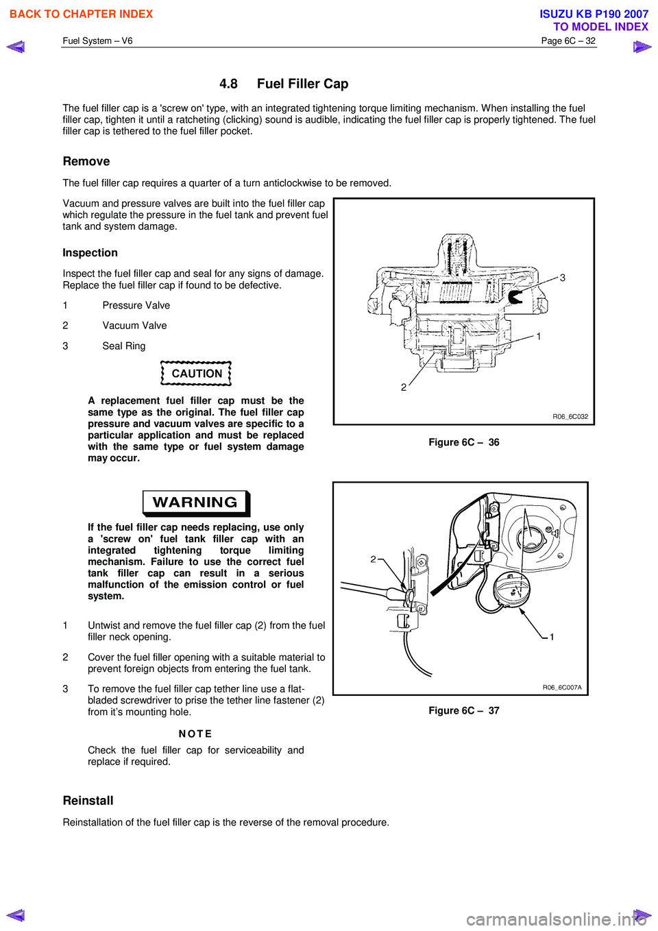
Vacuum and pressure valves are built into the fuel filler cap
which regulate the pressure in the fuel tank and prevent fuel
tank and system damage.
Inspection
Inspect the fuel filler cap and seal for any signs of damage.
Replace the fuel filler cap if found to be defective.
1 Pressure Valve
2 Vacuum Valve
3 Seal Ring
A replacement fuel filler cap must be the
same type as the original. The fuel filler cap
pressure and vacuum valves are specific to a
particular application and must be replaced
with the same type or fuel system damage
may occur.
Figure 6C – 36
If the fuel filler cap needs replacing, use only
a 'screw on' fuel tank filler cap with an
integrated tightening torque limiting
mechanism. Failure to use the correct fuel
tank filler cap can result in a serious
malfunction of the emission control or fuel
system.
1 Untwist and remove the fuel filler cap (2) from the fuel filler neck opening.
2 Cover the fuel filler opening with a suitable material to prevent foreign objects from entering the fuel tank.
3 To remove the fuel filler cap tether line use a flat- bladed screwdriver to prise the tether line fastener (2)
from it’s mounting hole.
NOTE
Check the fuel filler cap for serviceability and
replace if required.
Figure 6C – 37
Reinstall
Reinstallation of the fuel filler cap is the reverse of the removal procedure.
BACK TO CHAPTER INDEX
TO MODEL INDEX
ISUZU KB P190 2007
Page 3256 of 6020
Engine Management – V6 – General Information Page 6C1-1–14
Throttle Body Relearn Procedure
The ECM stores values that include the lowest possible TP sensor positions (zero percent), the rest positions (seven
percent), and the spring return rate. These values will only be erased or overwritten if the ECM is reprogrammed or if a
throttle body relearn procedure is performed.
NOTE
If the battery has been disconnected, the ECM
performs a throttle body relearn procedure once
the battery has been reconnected and the ignition
turned on.
The ECM performs a throttle body relearn procedure anytime the ignition is turned on and the following conditions have
been met:
• The engine has been off for greater than 29 seconds,
• The engine speed is less than 40 rpm,
• The vehicle speed is 0 km/h,
• The engine coolant temperature (ECT) is 5 – 60°C; if Tech 2 is used to perform the relearn procedure, the ECT is
5 – 100°C,
• The intake air temperature (IAT) is greater than 5 – 60°C; if Tech 2 is used to perform the relearn procedure, the
IAT is 5 – 100°C,
• The APP sensor angle is less than 15 percent, and
• Ignition voltage is greater than 10 V.
The throttle body relearn procedure is performed 29 seconds after the ignition is turned on. The ECM commands the
throttle plate from the rest position (seven percent open) to full closed (zero percent), then to around 10 percent open.
This procedure takes about six – eight seconds. If any faults occur in the TAC system, a DTC sets. At the start of this
procedure, the Tech 2 TAC Learn Counter parameter should display 0, then count up to 11 after the procedure is
completed. If the counter did not start at 0, or if the counter did not end at 11, a fault has occurred and a DTC should set.
TAC System Default Actions / Reduce Power Modes
The ECM switches to the following reduce power modes if the ECM detects a fault condition in the TAC system:
• If an APP sensor circuit fault or TP sensor circuit fault is detected, the ECM limits engine torque so the vehicle
cannot reach speeds of greater than 100 km/h. The ECM remains in this reduce power mode during the entire
ignition cycle, even if the fault is corrected.
• If there is a fault condition with the throttle actuator control circuits, a throttle actuator command vs. actual position
fault, a return spring check fault, or a TP sensor one circuit fault, the ECM limits engine speed to 2500 rpm and
three – six fuel injectors are randomly disabled. At this time the reduce power indicator is commanded on. The
ECM remains in the reduce power mode during the entire ignition cycle even if the fault is corrected.
NOTE
If a TP sensor one or throttle actuator control
circuit fault is present at the time the vehicle is at
idle, with no accelerator pedal angle, the engine
may stall.
Forced Engine Shutdown
A further safety feature which is built into the TAC system is the ECM will initiate an engine shut down if, the ECM’s
internal monitoring functions detects a serious internal fault, the fuel injectors will be turned off.
3.6 Cruise Control System
The cruise control system integrates with the engine control module (ECM) through the powertrain interface module
(PIM), to control the electronic throttle actuator and maintain the vehicle at the speed set by the driver.
BACK TO CHAPTER INDEX
TO MODEL INDEX
ISUZU KB P190 2007
Page 3259 of 6020
Engine Management – V6 – General Information Page 6C1-1–17
3.9 Serial Data Communication System
The engine control module (ECM) communicates directly with the following control units using the General Motors local
area network (GM LAN) serial data communication protocol:
• Transmission control module (TCM) (if fitted)
• Powertrain interface module (PIM)
The immobiliser control unit (ICU) communicates directly with the PIM using Keyword 2000 serial data communication
protocol. Refer to 11A Immobiliser for further information
As the GM LAN serial data communication protocol is not compatible with the Keyword 2000 serial data communication
protocol, a powertrain interface module (PIM) is integrated to the serial data communication system to perform the
following tasks (Refer to 6E1 Powertrain Interface Module – V6):
• Translate the GM LAN serial data transmitted by the ECM into a Keyword 2000 serial data that can be received
and recognised by the ICU.
• Translate the cruise control switch, automatic transmission power mode switch and 3
rd start switch signal into a GM
LAN serial data that can be received and recognised by the ECM.
3.10 Self Diagnostics System
The ECM constantly performs self-diagnostic tests on the engine management system. W hen the ECM detects a
malfunction, it also stores a diagnostic trouble code (DTC). A stored DTC will identify the problem area(s) and is
designed to assist the technician in rectifying the fault. In addition, DTCs are classified as either Current or History DTC.
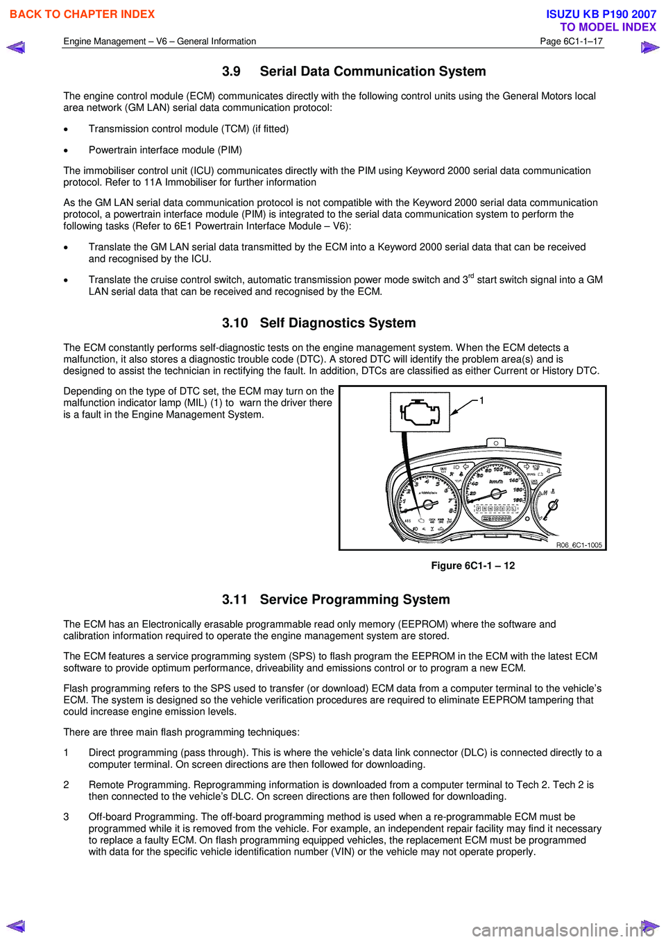
Depending on the type of DTC set, the ECM may turn on the
malfunction indicator lamp (MIL) (1) to warn the driver there
is a fault in the Engine Management System.
Figure 6C1-1 – 12
3.11 Service Programming System
The ECM has an Electronically erasable programmable read only memory (EEPROM) where the software and
calibration information required to operate the engine management system are stored.
The ECM features a service programming system (SPS) to flash program the EEPROM in the ECM with the latest ECM
software to provide optimum performance, driveability and emissions control or to program a new ECM.
Flash programming refers to the SPS used to transfer (or download) ECM data from a computer terminal to the vehicle’s
ECM. The system is designed so the vehicle verification procedures are required to eliminate EEPROM tampering that
could increase engine emission levels.
There are three main flash programming techniques:
1 Direct programming (pass through). This is where the vehicle’s data link connector (DLC) is connected directly to a computer terminal. On screen directions are then followed for downloading.
2 Remote Programming. Reprogramming information is downloaded from a computer terminal to Tech 2. Tech 2 is then connected to the vehicle’s DLC. On screen directions are then followed for downloading.
3 Off-board Programming. The off-board programming method is used when a re-programmable ECM must be programmed while it is removed from the vehicle. For example, an independent repair facility may find it necessary
to replace a faulty ECM. On flash programming equipped vehicles, the replacement ECM must be programmed
with data for the specific vehicle identification number (VIN) or the vehicle may not operate properly.
BACK TO CHAPTER INDEX
TO MODEL INDEX
ISUZU KB P190 2007
Page 3262 of 6020
Engine Management – V6 – General Information Page 6C1-1–20
4.3 Barometric Pressure Sensor
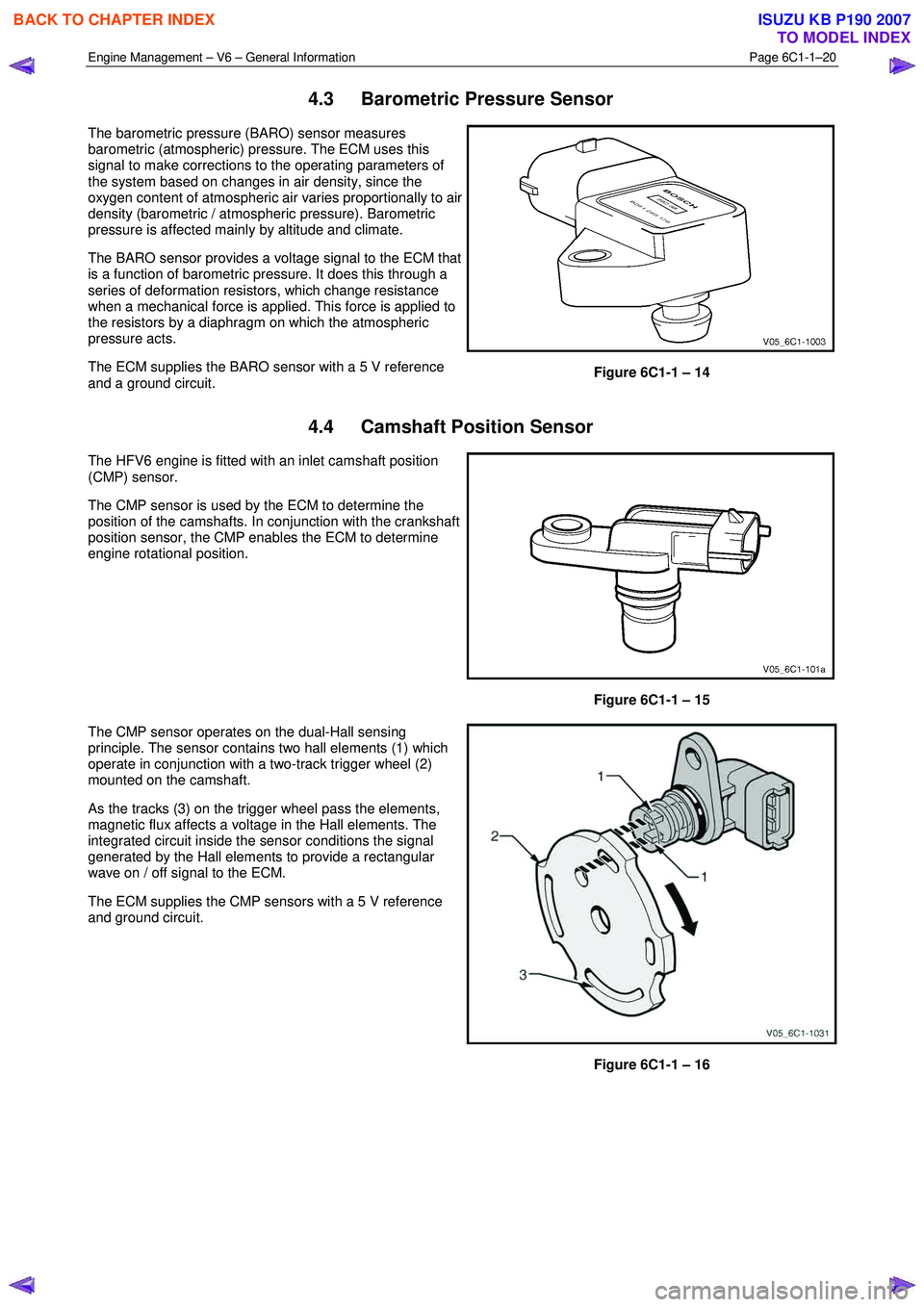
The barometric pressure (BARO) sensor measures
barometric (atmospheric) pressure. The ECM uses this
signal to make corrections to the operating parameters of
the system based on changes in air density, since the
oxygen content of atmospheric air varies proportionally to air
density (barometric / atmospheric pressure). Barometric
pressure is affected mainly by altitude and climate.
The BARO sensor provides a voltage signal to the ECM that
is a function of barometric pressure. It does this through a
series of deformation resistors, which change resistance
when a mechanical force is applied. This force is applied to
the resistors by a diaphragm on which the atmospheric
pressure acts.
The ECM supplies the BARO sensor with a 5 V reference
and a ground circuit.
Figure 6C1-1 – 14
4.4 Camshaft Position Sensor
The HFV6 engine is fitted with an inlet camshaft position
(CMP) sensor.
The CMP sensor is used by the ECM to determine the
position of the camshafts. In conjunction with the crankshaft
position sensor, the CMP enables the ECM to determine
engine rotational position.
Figure 6C1-1 – 15
The CMP sensor operates on the dual-Hall sensing
principle. The sensor contains two hall elements (1) which
operate in conjunction with a two-track trigger wheel (2)
mounted on the camshaft.
As the tracks (3) on the trigger wheel pass the elements,
magnetic flux affects a voltage in the Hall elements. The
integrated circuit inside the sensor conditions the signal
generated by the Hall elements to provide a rectangular
wave on / off signal to the ECM.
The ECM supplies the CMP sensors with a 5 V reference
and ground circuit.
Figure 6C1-1 – 16
BACK TO CHAPTER INDEX
TO MODEL INDEX
ISUZU KB P190 2007
Page 3263 of 6020
Engine Management – V6 – General Information Page 6C1-1–21
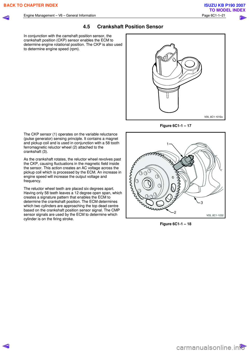
4.5 Crankshaft Position Sensor
In conjunction with the camshaft position sensor, the
crankshaft position (CKP) sensor enables the ECM to
determine engine rotational position. The CKP is also used
to determine engine speed (rpm).
Figure 6C1-1 – 17
The CKP sensor (1) operates on the variable reluctance
(pulse generator) sensing principle. It contains a magnet
and pickup coil and is used in conjunction with a 58 tooth
ferromagnetic reluctor wheel (2) attached to the
crankshaft (3).
As the crankshaft rotates, the reluctor wheel revolves past
the CKP, causing fluctuations in the magnetic field inside
the sensor. This action creates an AC voltage across the
pickup coil which is processed by the ECM. An increase in
engine speed will increase the output voltage and
frequency.
The reluctor wheel teeth are placed six degrees apart.
Having only 58 teeth leaves a 12 degree open span, which
creates a signature pattern that enables the ECM to
determine the crankshaft position. The ECM determines
which two cylinders are approaching the top dead centre
based on the crankshaft position sensor signal. The CMP
sensor signals are used by the ECM to determine which
cylinder is on the firing stroke.
Figure 6C1-1 – 18
BACK TO CHAPTER INDEX
TO MODEL INDEX
ISUZU KB P190 2007
Page 3268 of 6020
Engine Management – V6 – General Information Page 6C1-1–26
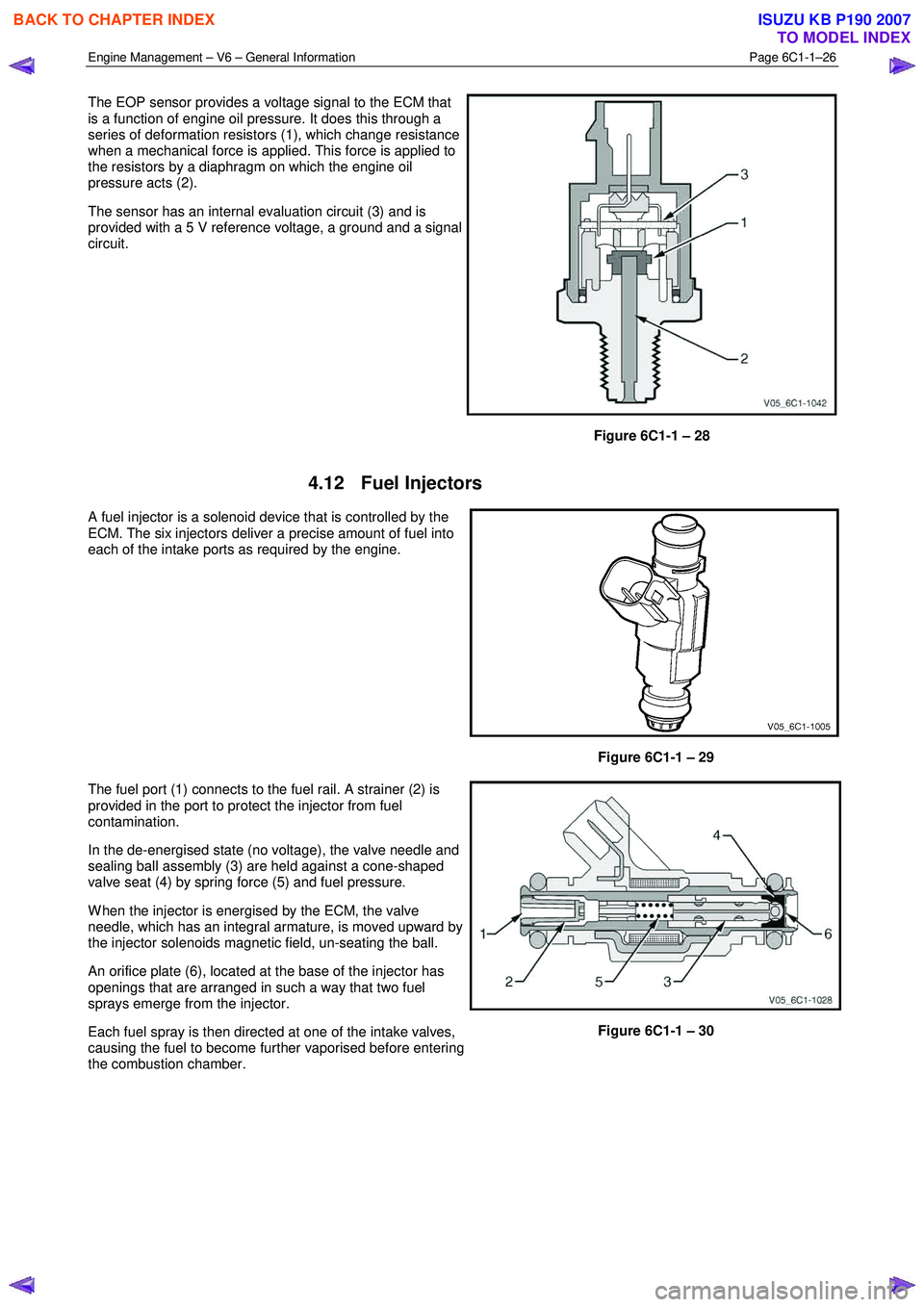
The EOP sensor provides a voltage signal to the ECM that
is a function of engine oil pressure. It does this through a
series of deformation resistors (1), which change resistance
when a mechanical force is applied. This force is applied to
the resistors by a diaphragm on which the engine oil
pressure acts (2).
The sensor has an internal evaluation circuit (3) and is
provided with a 5 V reference voltage, a ground and a signal
circuit.
Figure 6C1-1 – 28
4.12 Fuel Injectors
A fuel injector is a solenoid device that is controlled by the
ECM. The six injectors deliver a precise amount of fuel into
each of the intake ports as required by the engine.
Figure 6C1-1 – 29
The fuel port (1) connects to the fuel rail. A strainer (2) is
provided in the port to protect the injector from fuel
contamination.
In the de-energised state (no voltage), the valve needle and
sealing ball assembly (3) are held against a cone-shaped
valve seat (4) by spring force (5) and fuel pressure.
W hen the injector is energised by the ECM, the valve
needle, which has an integral armature, is moved upward by
the injector solenoids magnetic field, un-seating the ball.
An orifice plate (6), located at the base of the injector has
openings that are arranged in such a way that two fuel
sprays emerge from the injector.
Each fuel spray is then directed at one of the intake valves,
causing the fuel to become further vaporised before entering
the combustion chamber.
Figure 6C1-1 – 30
BACK TO CHAPTER INDEX
TO MODEL INDEX
ISUZU KB P190 2007
Page 3274 of 6020
Engine Management – V6 – General Information Page 6C1-1–32
4.16 Intake Air Temperature Sensor
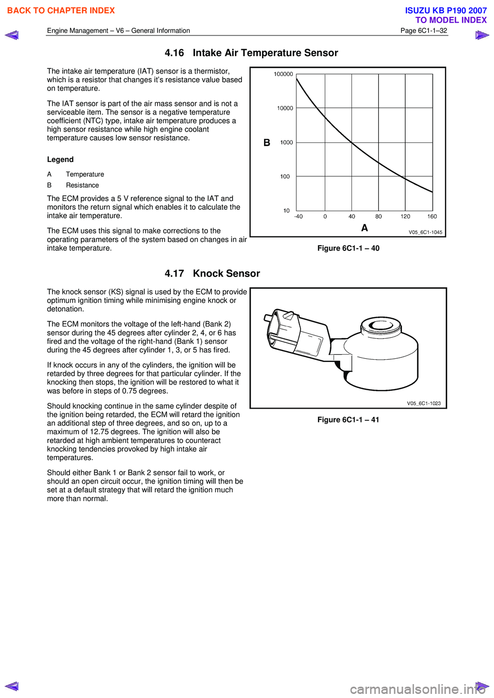
The intake air temperature (IAT) sensor is a thermistor,
which is a resistor that changes it’s resistance value based
on temperature.
The IAT sensor is part of the air mass sensor and is not a
serviceable item. The sensor is a negative temperature
coefficient (NTC) type, intake air temperature produces a
high sensor resistance while high engine coolant
temperature causes low sensor resistance.
Legend
A Temperature
B Resistance
The ECM provides a 5 V reference signal to the IAT and
monitors the return signal which enables it to calculate the
intake air temperature.
The ECM uses this signal to make corrections to the
operating parameters of the system based on changes in air
intake temperature.
Figure 6C1-1 – 40
4.17 Knock Sensor
The knock sensor (KS) signal is used by the ECM to provide
optimum ignition timing while minimising engine knock or
detonation.
The ECM monitors the voltage of the left-hand (Bank 2)
sensor during the 45 degrees after cylinder 2, 4, or 6 has
fired and the voltage of the right-hand (Bank 1) sensor
during the 45 degrees after cylinder 1, 3, or 5 has fired.
If knock occurs in any of the cylinders, the ignition will be
retarded by three degrees for that particular cylinder. If the
knocking then stops, the ignition will be restored to what it
was before in steps of 0.75 degrees.
Should knocking continue in the same cylinder despite of
the ignition being retarded, the ECM will retard the ignition
an additional step of three degrees, and so on, up to a
maximum of 12.75 degrees. The ignition will also be
retarded at high ambient temperatures to counteract
knocking tendencies provoked by high intake air
temperatures.
Should either Bank 1 or Bank 2 sensor fail to work, or
should an open circuit occur, the ignition timing will then be
set at a default strategy that will retard the ignition much
more than normal.
Figure 6C1-1 – 41
BACK TO CHAPTER INDEX
TO MODEL INDEX
ISUZU KB P190 2007
Page 3276 of 6020
Engine Management – V6 – General Information Page 6C1-1–34
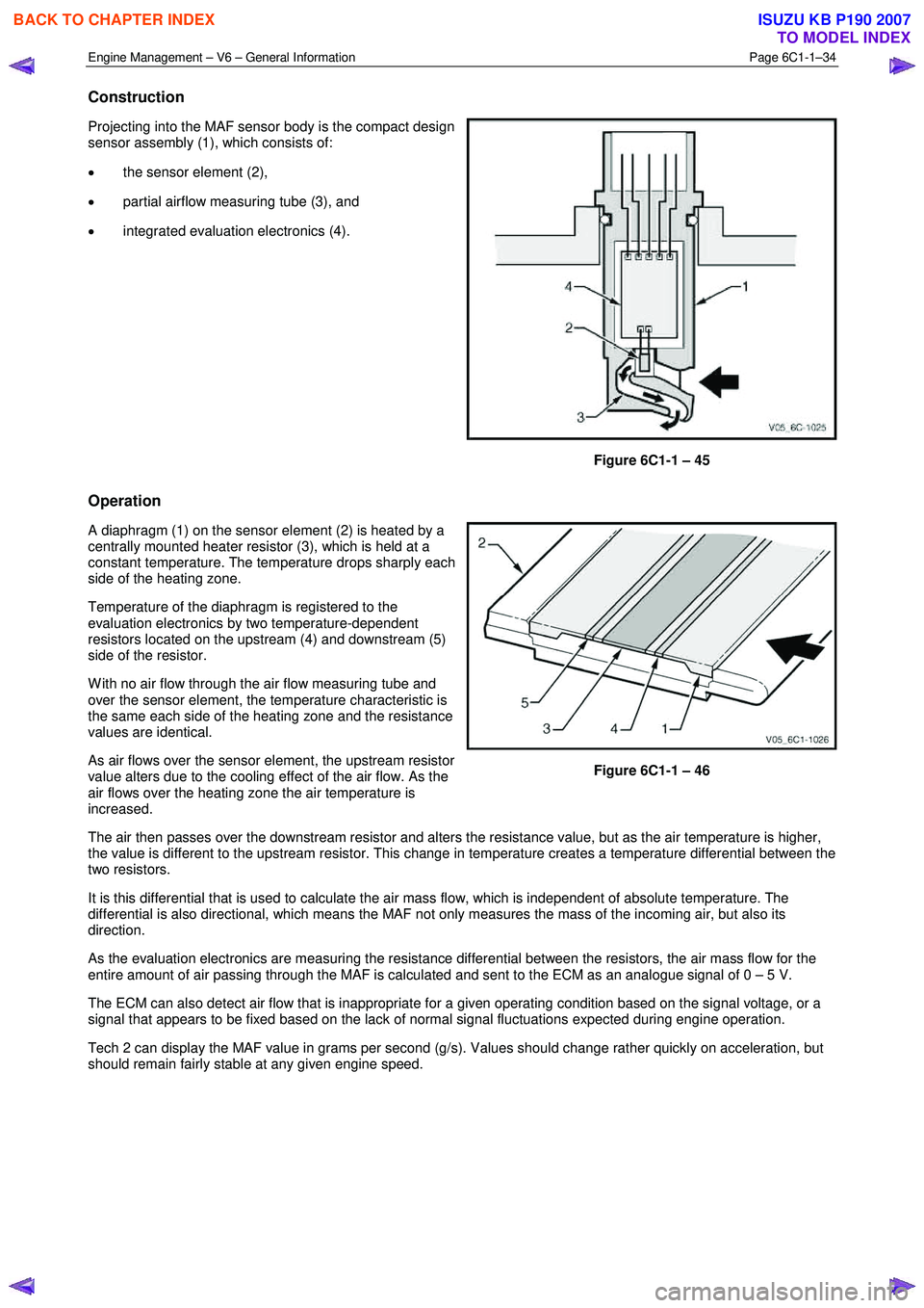
Construction
Projecting into the MAF sensor body is the compact design
sensor assembly (1), which consists of:
• the sensor element (2),
• partial airflow measuring tube (3), and
• integrated evaluation electronics (4).
Figure 6C1-1 – 45
Operation
A diaphragm (1) on the sensor element (2) is heated by a
centrally mounted heater resistor (3), which is held at a
constant temperature. The temperature drops sharply each
side of the heating zone.
Temperature of the diaphragm is registered to the
evaluation electronics by two temperature-dependent
resistors located on the upstream (4) and downstream (5)
side of the resistor.
W ith no air flow through the air flow measuring tube and
over the sensor element, the temperature characteristic is
the same each side of the heating zone and the resistance
values are identical.
As air flows over the sensor element, the upstream resistor
value alters due to the cooling effect of the air flow. As the
air flows over the heating zone the air temperature is
increased.
Figure 6C1-1 – 46
The air then passes over the downstream resistor and alters the resistance value, but as the air temperature is higher,
the value is different to the upstream resistor. This change in temperature creates a temperature differential between the
two resistors.
It is this differential that is used to calculate the air mass flow, which is independent of absolute temperature. The
differential is also directional, which means the MAF not only measures the mass of the incoming air, but also its
direction.
As the evaluation electronics are measuring the resistance differential between the resistors, the air mass flow for the
entire amount of air passing through the MAF is calculated and sent to the ECM as an analogue signal of 0 – 5 V.
The ECM can also detect air flow that is inappropriate for a given operating condition based on the signal voltage, or a
signal that appears to be fixed based on the lack of normal signal fluctuations expected during engine operation.
Tech 2 can display the MAF value in grams per second (g/s). Values should change rather quickly on acceleration, but
should remain fairly stable at any given engine speed.
BACK TO CHAPTER INDEX
TO MODEL INDEX
ISUZU KB P190 2007