Page 3067 of 6020
Engine Mechanical – V6 Page 6A1–290
Page 6A1–290
NOTE
Do not rotate the crankshaft.
9 Allow the assembly to sit for 2 minutes.
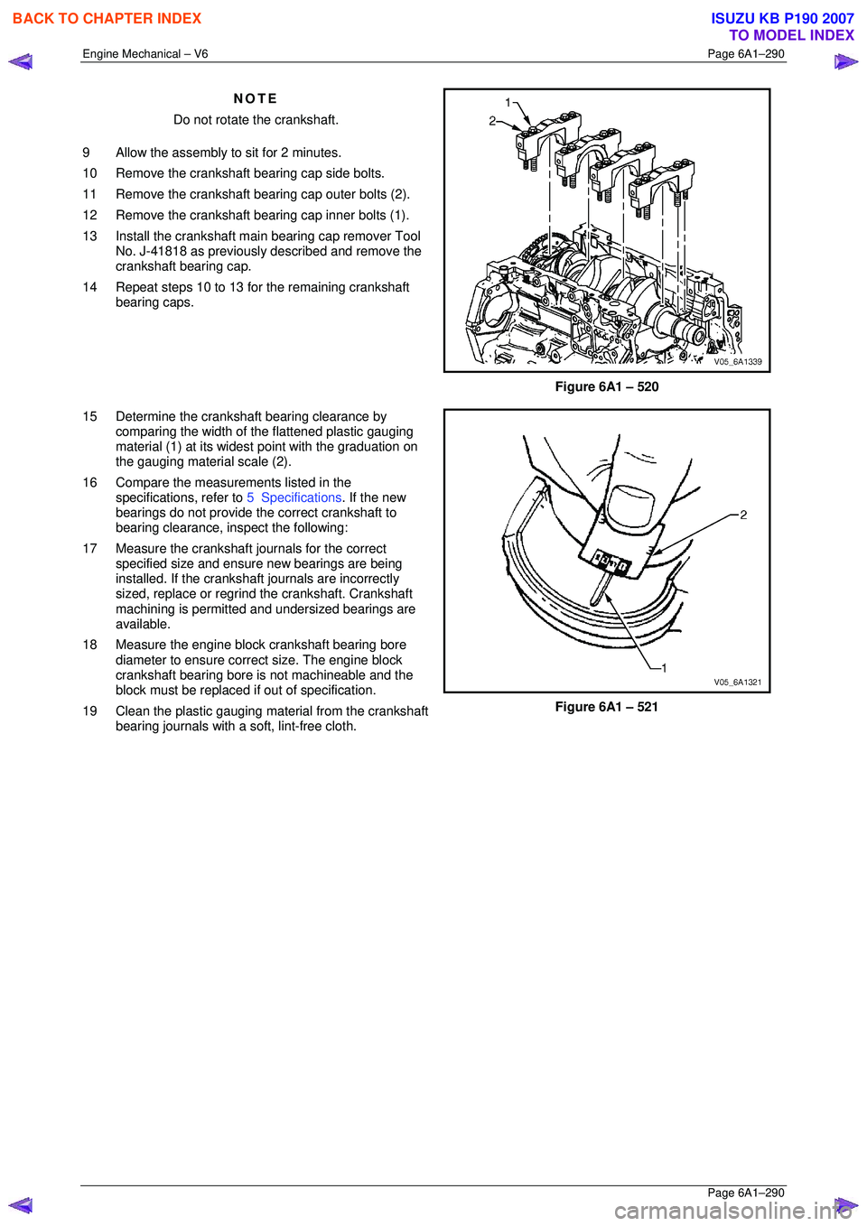
10 Remove the crankshaft bearing cap side bolts.
11 Remove the crankshaft bearing cap outer bolts (2).
12 Remove the crankshaft bearing cap inner bolts (1).
13 Install the crankshaft main bearing cap remover Tool No. J-41818 as previously described and remove the
crankshaft bearing cap.
14 Repeat steps 10 to 13 for the remaining crankshaft bearing caps.
Figure 6A1 – 520
15 Determine the crankshaft bearing clearance by comparing the width of the flattened plastic gauging
material (1) at its widest point with the graduation on
the gauging material scale (2).
16 Compare the measur ements listed in the
specifications, refer to 5 Specifications. If the new
bearings do not provide the correct crankshaft to
bearing clearance, inspect the following:
17 Measure the crankshaft journals for the correct specified size and ensure new bearings are being
installed. If the crankshaft journals are incorrectly
sized, replace or regrind the crankshaft. Crankshaft
machining is permitted and undersized bearings are
available.
18 Measure the engine block crankshaft bearing bore diameter to ensure correct size. The engine block
crankshaft bearing bore is not machineable and the
block must be replaced if out of specification.
19 Clean the plastic gauging material from the crankshaft bearing journals with a soft, lint-free cloth.
Figure 6A1 – 521
BACK TO CHAPTER INDEX
TO MODEL INDEX
ISUZU KB P190 2007
Page 3082 of 6020
Engine Mechanical – V6 Page 6A1–305
Page 6A1–305
NOTE
All swarf must be removed from the drilled hole
prior to tapping.
Safety glasses must be worn when using
compressed air.
3 Using compressed air, clean out any swarf.
Figure 6A1 – 557
NOTE
A correctly counter bored hole will show a slight
burnishing on the surface of the base material
for 360 degrees around the drilled hole.
4 Counter bore the drilled hole to the full depth permitted by the tool (1).
Figure 6A1 – 558
NOTE
All swarf must be removed from the drilled hole
prior to tapping.
Safety glasses must be worn when using
compressed air.
5 Using compressed air, clean out any swarf.
Figure 6A1 – 559
BACK TO CHAPTER INDEX
TO MODEL INDEX
ISUZU KB P190 2007
Page 3143 of 6020
Engine Cooling – V6 Engine Page 6B1–8
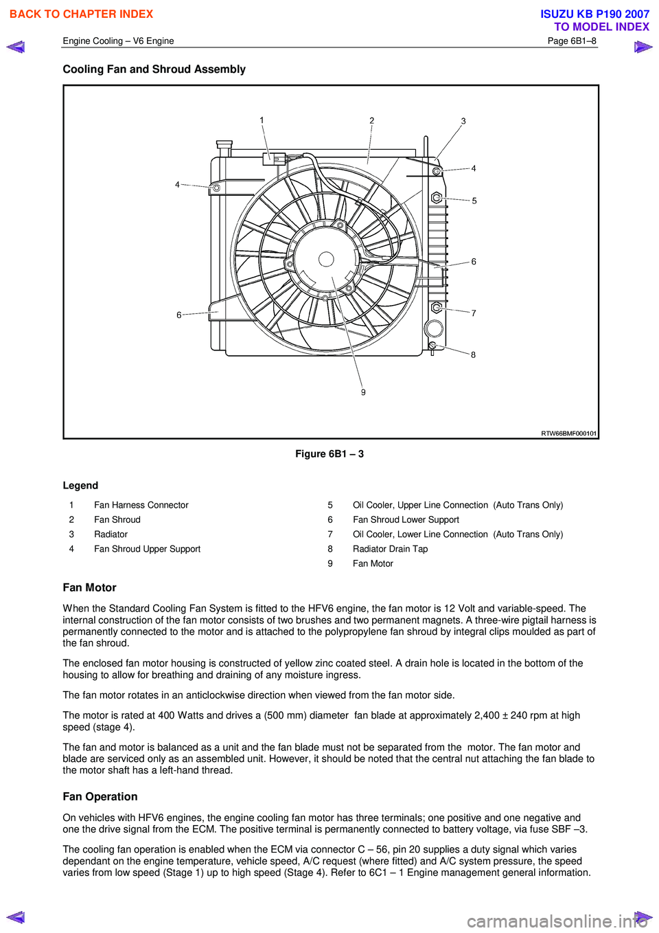
Cooling Fan and Shroud Assembly
Figure 6B1 – 3
Legend
1 Fan Harness Connector
2 Fan Shroud
3 Radiator
4 Fan Shroud Upper Support 5 Oil Cooler, Upper Line Connection (Auto Trans Only)
6 Fan Shroud Lower Support
7 Oil Cooler, Lower Line Connection (Auto Trans Only)
8 Radiator Drain Tap
9 Fan Motor
Fan Motor
W hen the Standard Cooling Fan System is fitted to the HFV6 engine, the fan motor is 12 Volt and variable-speed. The
internal construction of the fan motor consists of two brushes and two permanent magnets. A three-wire pigtail harness is
permanently connected to the motor and is attached to the polypropylene fan shroud by integral clips moulded as part of
the fan shroud.
The enclosed fan motor housing is constructed of yellow zinc coated steel. A drain hole is located in the bottom of the
housing to allow for breathing and draining of any moisture ingress.
The fan motor rotates in an anticlockwise direction when viewed from the fan motor side.
The motor is rated at 400 W atts and drives a (500 mm) diameter fan blade at approximately 2,400 ± 240 rpm at high
speed (stage 4).
The fan and motor is balanced as a unit and the fan blade must not be separated from the motor. The fan motor and
blade are serviced only as an assembled unit. However, it should be noted that the central nut attaching the fan blade to
the motor shaft has a left-hand thread.
Fan Operation
On vehicles with HFV6 engines, the engine cooling fan motor has three terminals; one positive and one negative and
one the drive signal from the ECM. The positive terminal is permanently connected to battery voltage, via fuse SBF –3.
The cooling fan operation is enabled when the ECM via connector C – 56, pin 20 supplies a duty signal which varies
dependant on the engine temperature, vehicle speed, A/C request (where fitted) and A/C system pressure, the speed
varies from low speed (Stage 1) up to high speed (Stage 4). Refer to 6C1 – 1 Engine management general information.
BACK TO CHAPTER INDEX
TO MODEL INDEX
ISUZU KB P190 2007
Page 3149 of 6020
Engine Cooling – V6 Engine Page 6B1–14
2.7 Coolant Recovery Reservoir
The coolant is maintained at the ideal level in the radiator by the coolant filler cap and the coolant recovery reservoir,
resulting in increased cooling efficiency.
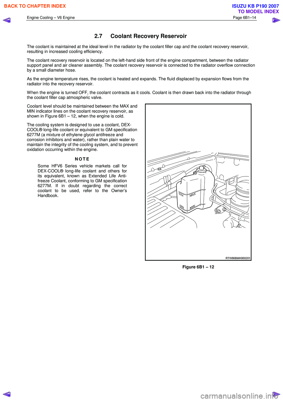
The coolant recovery reservoir is located on the left-hand side front of the engine compartment, between the radiator
support panel and air cleaner assembly. The coolant recovery reservoir is connected to the radiator overflow connection
by a small diameter hose.
As the engine temperature rises, the coolant is heated and expands. The fluid displaced by expansion flows from the
radiator into the recovery reservoir.
W hen the engine is turned OFF, the coolant contracts as it cools. Coolant is then drawn back into the radiator through
the coolant filler cap atmospheric valve.
Coolant level should be maintained between the MAX and
MIN indicator lines on the coolant recovery reservoir, as
shown in Figure 6B1 – 12, when the engine is cold.
The cooling system is designed to use a coolant, DEX-
COOL® long-life coolant or equivalent to GM specification
6277M (a mixture of ethylene glycol antifreeze and
corrosion inhibitors and water), rather than plain water to
maintain the integrity of the cooling system, and to prevent
oxidation occurring within the engine.
NOTE
Some HFV6 Series vehicle markets call for
DEX-COOL® long-life coolant and others for
its equivalent, known as Extended Life Anti-
freeze Coolant, conforming to GM specification
6277M. If in doubt regarding the correct
coolant to be used, refer to the Owner’s
Handbook.
Figure 6B1 – 12
BACK TO CHAPTER INDEX
TO MODEL INDEX
ISUZU KB P190 2007
Page 3185 of 6020
Engine Cooling – V6 Engine Page 6B1–50
When removing, transporting or installing the
fan and shroud assembly, do not grasp the
assembly by the fan rings (1) as this may
bend the fan motor shaft and cause fan
vibrations
Figure 6B3 – 56
When handling the fan assembly, always hold
the assembly at the fan shroud (1).
Figure 6B3 – 57
Install
Installation of the cooling fan and shroud assembly is the reverse of removal procedures, noting the following points:
1 Ensure that fan and shroud assembly to radiator attaching clips are fully engaged.
2 Ensure that the top automatic transmission cooling pipe (if fitted) is installed to the integral shroud clip.
3 Check cooling fan operation. Refer to 6C1-2 Engine Management Diagnostics. Also check for correct rotational direction of the cooling fan.
BACK TO CHAPTER INDEX
TO MODEL INDEX
ISUZU KB P190 2007
Page 3186 of 6020
Engine Cooling – V6 Engine Page 6B1–51
Disassemble
1 Remove cooling fan and shroud assembly as previously described.
NOTE
Neither fan is to be separated from its fan motor.
The assembly is carefully balanced during
manufacture and duplicating this balance on
reassembly, is not possible.
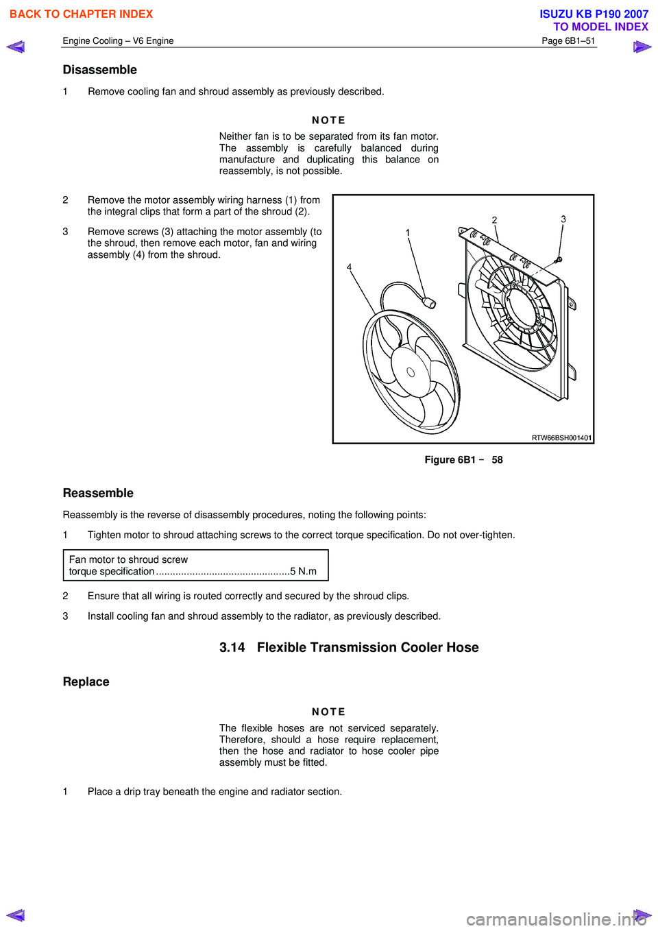
2 Remove the motor assembly wiring harness (1) from the integral clips that form a part of the shroud (2).
3 Remove screws (3) attaching the motor assembly (to the shroud, then remove each motor, fan and wiring
assembly (4) from the shroud.
Figure 6B1 –
––
–
58
Reassemble
Reassembly is the reverse of disassembly procedures, noting the following points:
1 Tighten motor to shroud attaching screws to the correct torque specification. Do not over-tighten.
Fan motor to shroud screw
torque specification ................................................5 N.m
2 Ensure that all wiring is routed correctly and secured by the shroud clips.
3 Install cooling fan and shroud assembly to the radiator, as previously described.
3.14 Flexible Transmission Cooler Hose
Replace
NOTE
The flexible hoses are not serviced separately.
Therefore, should a hose require replacement,
then the hose and radiator to hose cooler pipe
assembly must be fitted.
1 Place a drip tray beneath the engine and radiator section.
BACK TO CHAPTER INDEX
TO MODEL INDEX
ISUZU KB P190 2007
Page 3191 of 6020
Engine Cooling – V6 Engine Page 6B1–56
Reinstall
Installation of the radiator is the reverse of removal procedures, noting the following points:
1 Before installing radiator, inspect core to ensure that there is no foreign matter in core fins. Clean out between core fins with compressed air, blowing from rear to front.
2 If the vehicle is fitted with an automatic transmission, remove plugs from the removed cooling pipe ends and the two quick connect fittings.
3 After wiping cooler line ends and smearing clean automatic transmission fluid over each flared line end, push into the quick connect fitting to engage. As a security check, tug on each line to ensure correct engagement.
4 Check the transmission fluid level. Refer to the following references as required:
• 7C4 Automatic Transmission
• 4L60E On-vehicle Servicing
5 Install the following hoses:
a. Lower radiator hose, securing with the hose clamp.
b. Upper radiator hose, securing with the hose clamp.
6 Install the radiator cooling fan and shroud assembly. Refer to 3.13Cooling Fan and Shroud Assembly in this Section. Ensure that electrical connectors and the transmission cooler lines are seated correctly in the integral
retainer clips before install upper radiator shroud.
7 Refill cooling system. Refer to 3.3 Draining and Filling Cooling System in this Section.
8 Check for coolant leaks. Refer to 3.7 Pressure Testing in this Section.
9 Reconnect battery ground lead. Refer to 8A Electrical Body & Chassis.
10 Check cooling fan operation. Refer to 6C1-2 Engine Management Diagnostics. Also check for correct rotational direction of cooling fan.
BACK TO CHAPTER INDEX
TO MODEL INDEX
ISUZU KB P190 2007
Page 3208 of 6020
Fuel System – V6 Page 6C – 6
Fuel Pump
Single Turbine Fuel Pump
The fuel pump is an integral part of the Fuel Pump and Sender Assembly, refer to Figure 6C – 3.
Figure 6C– 2 details the fuel flow through the single turbine fuel pump.
Figure 6C– 2
Legend
Fuel
Vapour out 1 Inlet Body
2 Impeller Housing
3 Impeller
4 Fuel Pump Housing
BACK TO CHAPTER INDEX
TO MODEL INDEX
ISUZU KB P190 2007