2007 ISUZU KB P190 EGR
[x] Cancel search: EGRPage 2009 of 6020
ENGINE DIAGNOSIS (C24SE) 6-9
Abnormal Noise Due to Hydraulic Lash Adjuster
Should abnormal noise due to the hydraulic lash
adjuster trouble be heard immediately after the engine
is started, inspect as follows:
Condition Possible cause Correction
Abnormal noise is heard Air contaminated Bleed
HLA is spongy Check ball valve broken Repair
Safety valve in cylinder head
broken Replace
Valve clearance is not zero HLA inside stick
Replace HLA assembly
Troubleshooting Procedure
Short out each spark plug in sequence using insulated
spark plug wire removers. Locate cylinder with
defective bearing by listening for abnormal noise that
stops when spark plug is shorted out.
Condition Possible cause Correction
Noise from connecting rods or
from connecting rod bearings
(Faulty connecting rods or
connecting rod bearings usually
make an abnormal noise slightly
higher than the crank bearing
noise, which becomes more
evident when engine is
accelerated) Bearing or crankshaft pin worn Replace connecting rod bearings
and crankshaft or regrind
crankshaft and install the under
size bearing
Crankpin out of round Replace connecting rod bearings
and crankshaft or regrind
crankshaft and install the under
size bearing
Connecting rod bent Correct or replace
Connecting rod bearing seized Replace connecting rod bearings
and crankshaft or regrind
crankshaft and install the under
size bearing
Troubleshooting Procedure
Abnormal noise stops when the spark plug on the
cylinder with defective parts is shorted out.
Condition Possible cause Correction
Piston and cylinder
(Faulty piston or cylinder usually
makes a combined mechanical
thumping noise which increases
when engine is suddenly
accelerated but diminishes
gradually as the engine warms up) Piston clearance increased due to
cylinder wear Replace piston and cylinder body
Piston seized Replace piston and cylinder body
Piston ring broken Replace piston and cylinder body
Piston defective Replace pistons and others
BACK TO CHAPTER INDEX
TO MODEL INDEX
ISUZU KB P190 2007
Page 2058 of 6020
6A-44 ENGINE MECHANICAL (C24SE)
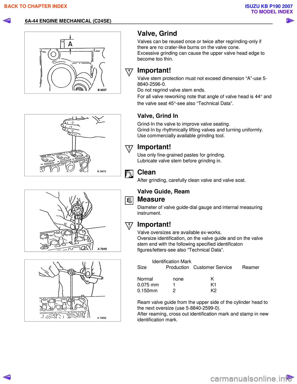
Valve, Grind
Valves can be reused once or twice after regrinding-only if
there are no crater-like burns on the valve cone.
Excessive grinding can cause the upper valve head edge to
become too thin.
Important!
Valve stem protection must not exceed dimension “A”-use 5-
8840-2596-0.
Do not regrind valve stem ends.
For all valve reworking note that angle of valve head is 44 °and
the valve seat 45 °-see also “Technical Data”.
Valve, Grind In
Grind-In the valve to improve valve seating.
Grind-In by rhythmically lifting valves and turning uniformly.
Use commercially available grinding tool.
Important!
Use only fine-grained pastes for grinding.
Lubricate valve stem before grinding in.
Clean
After grinding, carefully clean valve and valve soat.
Valve Guide, Ream
Measure
Diameter of valve guide-dial gauge and internal measuring
instrument.
Important!
Valve oversizes are available ex-works.
Oversize identification, on the valve guide and on the valve
stem end with the following specified identificaton
flgures/letters-see also “Technical Data”.
Identification Mark
Size Production Customer Service Reamer
Normal none K
0.075 mm 1 K1
0.150mm 2 K2
Ream valve guide from the upper side of the cylinder head to
the next oversize (use 5-8840-2599-0).
After reaming, cross out identification mark and stamp in new
identification mark.
BACK TO CHAPTER INDEX
TO MODEL INDEX
ISUZU KB P190 2007
Page 2059 of 6020
ENGINE MECHANICAL (C24SE) 6A-45
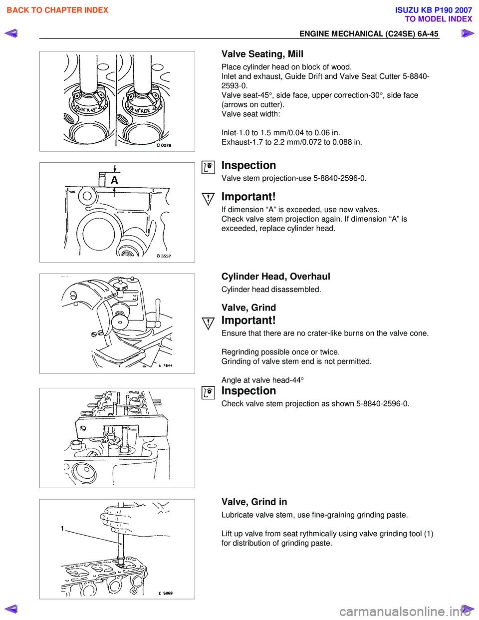
Valve Seating, Mill
Place cylinder head on block of wood.
Inlet and exhaust, Guide Drift and Valve Seat Cutter 5-8840-
2593-0.
Valve seat-45 °, side face, upper correction-30 °, side face
(arrows on cutter).
Valve seat width:
Inlet-1.0 to 1.5 mm/0.04 to 0.06 in.
Exhaust-1.7 to 2.2 mm/0.072 to 0.088 in.
Inspection
Valve stem projection-use 5-8840-2596-0.
Important!
If dimension “A” is exceeded, use new valves.
Check valve stem projection again. If dimension “A” is
exceeded, replace cylinder head.
Cylinder Head, Overhaul
Cylinder head disassembled.
Valve, Grind
Important!
Ensure that there are no crater-like burns on the valve cone.
Regrinding possible once or twice.
Grinding of valve stem end is not permitted.
Angle at valve head-44 °
Inspection
Check valve stem projection as shown 5-8840-2596-0.
Valve, Grind in
Lubricate valve stem, use fine-graining grinding paste.
Lift up valve from seat rythmically using valve grinding tool (1)
for distribution of grinding paste.
BACK TO CHAPTER INDEX
TO MODEL INDEX
ISUZU KB P190 2007
Page 2147 of 6020
6D2-4 IGNITION SYSTEM
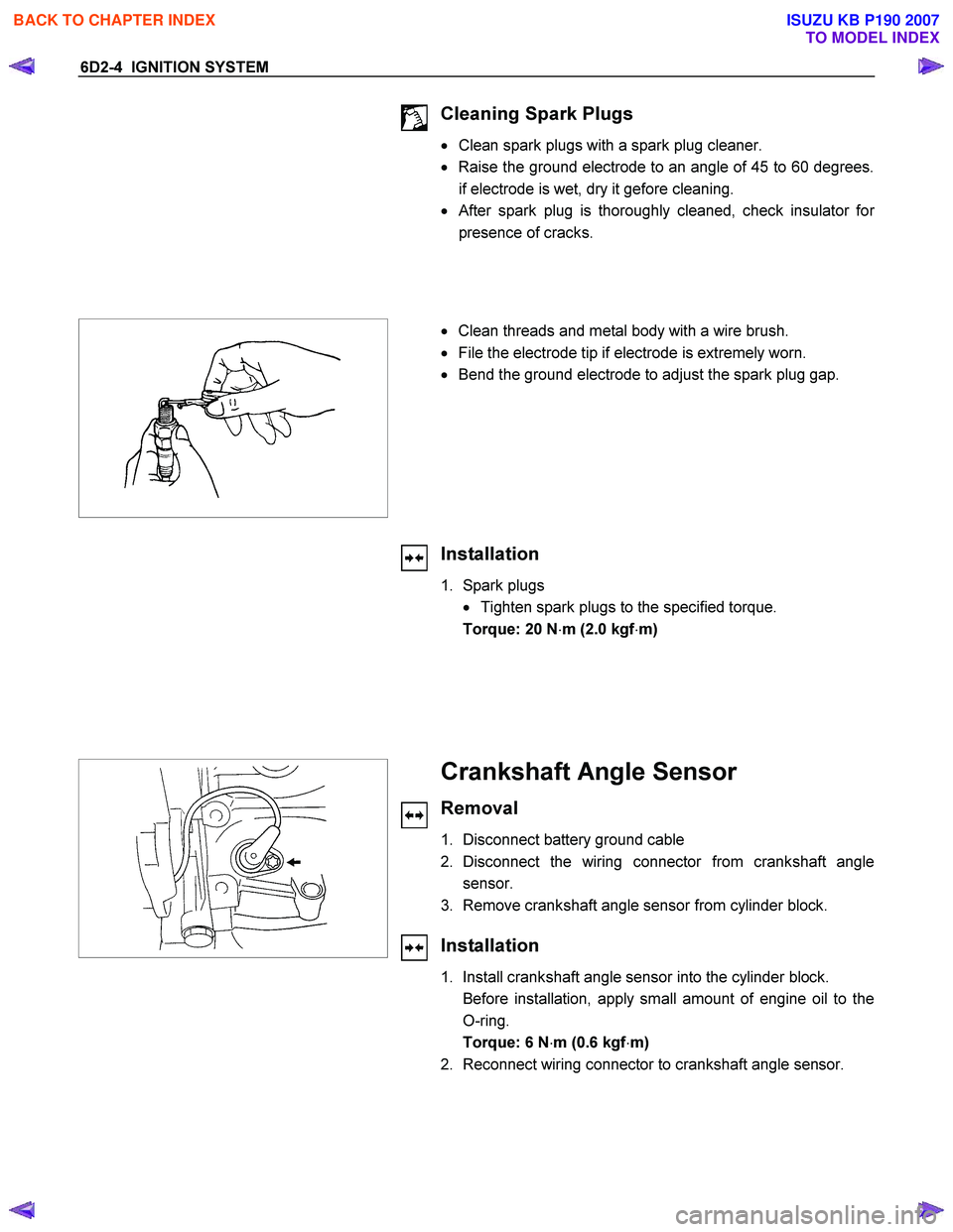
Cleaning Spark Plugs
• Clean spark plugs with a spark plug cleaner.
• Raise the ground electrode to an angle of 45 to 60 degrees.
if electrode is wet, dry it gefore cleaning.
•
After spark plug is thoroughly cleaned, check insulator for
presence of cracks.
• Clean threads and metal body with a wire brush.
• File the electrode tip if electrode is extremely worn.
• Bend the ground electrode to adjust the spark plug gap.
Installation
1. Spark plugs
• Tighten spark plugs to the specified torque.
Torque: 20 N ⋅m (2.0 kgf ⋅m)
Crankshaft Angle Sensor
Removal
1. Disconnect battery ground cable
2. Disconnect the wiring connector from crankshaft angle sensor.
3. Remove crankshaft angle sensor from cylinder block.
Installation
1. Install crankshaft angle sensor into the cylinder block.
Before installation, apply small amount of engine oil to the O-ring.
Torque: 6 N ⋅m (0.6 kgf ⋅m)
2. Reconnect wiring connector to crankshaft angle sensor.
BACK TO CHAPTER INDEX
TO MODEL INDEX
ISUZU KB P190 2007
Page 2155 of 6020
STARTING AND CHARGING SYSTEM 6D3-7
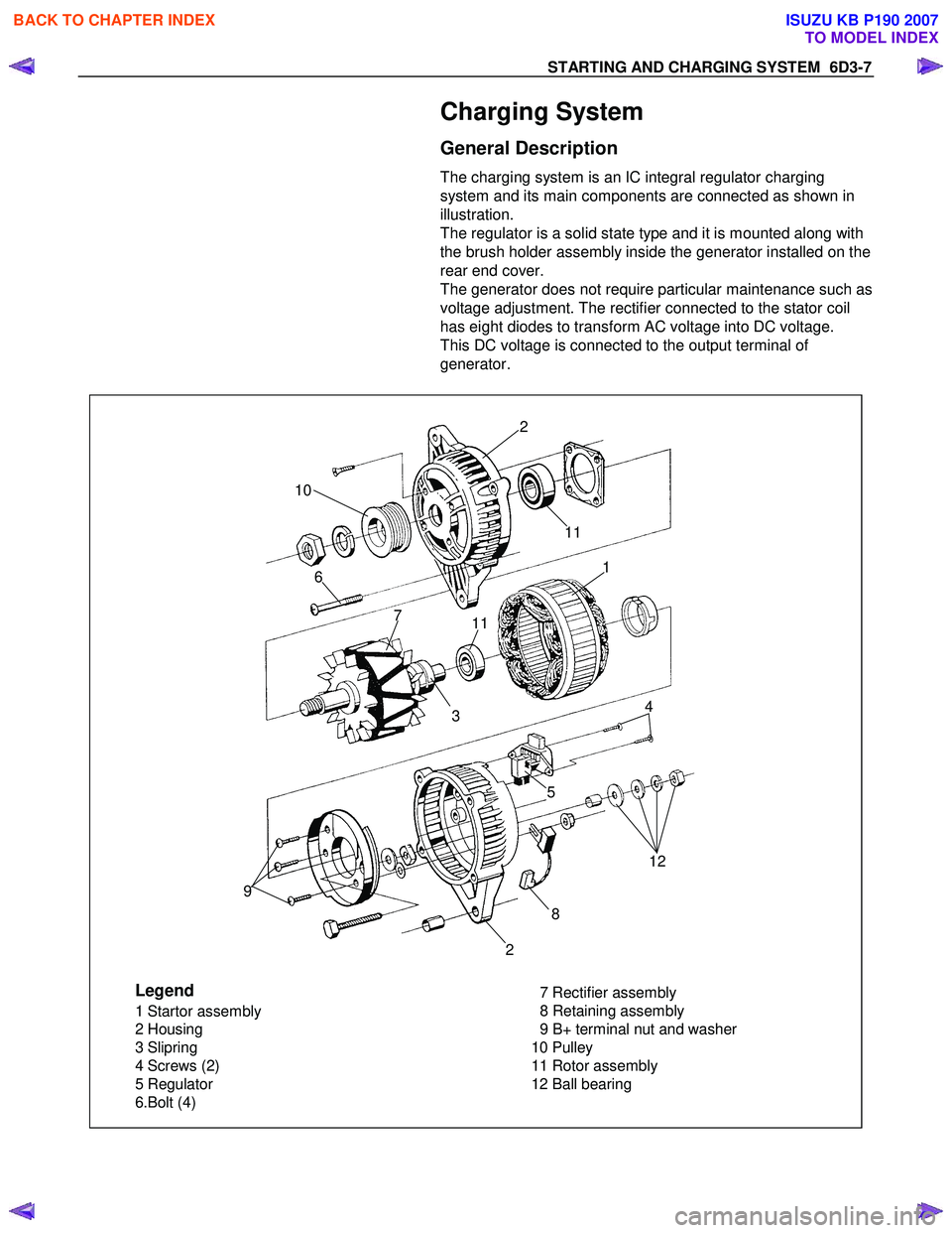
Charging System
General Description
The charging system is an IC integral regulator charging
system and its main components are connected as shown in
illustration.
The regulator is a solid state type and it is mounted along with
the brush holder assembly inside the generator installed on the
rear end cover.
The generator does not require particular maintenance such as
voltage adjustment. The rectifier connected to the stator coil
has eight diodes to transform AC voltage into DC voltage.
This DC voltage is connected to the output terminal of
generator.
Legend
1 Startor assembly
2 Housing
3 Slipring
4 Screws (2)
5 Regulator
6.Bolt (4) 7 Rectifier assembly
8 Retaining assembly
9 B+ terminal nut and washer
10 Pulley
11 Rotor assembly
12 Ball bearing
2
11
12
2 8
5
4
3 1
11
7
6
10
9
BACK TO CHAPTER INDEX
TO MODEL INDEX
ISUZU KB P190 2007
Page 2162 of 6020
6D3-14 STARTING AND CHARGING SYSTEM
7. To remove the pulley, mount an 8mm Allen key in the vice
with the short end upwards, place a 24mm ring spanner on
the puley nut, position the internal hexagon of the roto
r
shaft onto the Allen ken, loosen the nut and remove the
pulley.
Note: the pulley has an integral boss which locks up against
the bearing,
therefore no thrust collar is provided.
8. Removing the rotor assembly. Remove the four retaining screws from the drive end housing, withdraw the roto
r
complete with the bearing.
Note: the rotor must not be pressed from the drive end housing
using a press as the bearing retaining plate and drive end
housing will be damaged or distorted. Parts removed in this
way must be replaced if the integrity of the generator is to be
maintained.
9. Remove the drive end bearing from the rotor shaft using a
chuck type puler, take care not to distort the fan assembl
y
during this process.
10. Remove the slipring end bearing using the same meghod as in 9.
Clean
Thoroughly clean all components except the rotor and stator
with an approved cleaning agent. Ensure that all traced of oil
and dirt are removed. If an abrasive cleaner is used to remove
scale and paint from the housings take care not to abrade the
bearing and mounting spigot surfaces. The rotor and stator
must be cleaned with compressed air only, the use of solvents
could cause damage to the insulating materials.
Inspection
1. Rectifier assembly
The following test equipment is required.
The recitifier assembly is not repairable and must be replaced
if a faulty diode is detected during inspection.
(a)
Adiode tester where the DC output at the test probes does
not exceed 14 volts or in the case of AC testers 12 volts
RMS. This is to ensue that when inspection rectifiers fitted
with zener power diodes the forward and reverse checks
are completer and are not masked by the diode turning on
due to the zener breakdown voltage.
(b) A zenere diode tester with a DC output in excess of 30 volts, the tester should also incorporate internal current
limiting set to 5 Ma. to prevent high currents during
inspection.
(c) Diodes can be destroyed during service due to high temperature and overload, open circuits are usually a result
of excessive voltage.
BACK TO CHAPTER INDEX
TO MODEL INDEX
ISUZU KB P190 2007
Page 2202 of 6020
6E–32 ENGINE DRIVEABILITY AND EMISSIONS
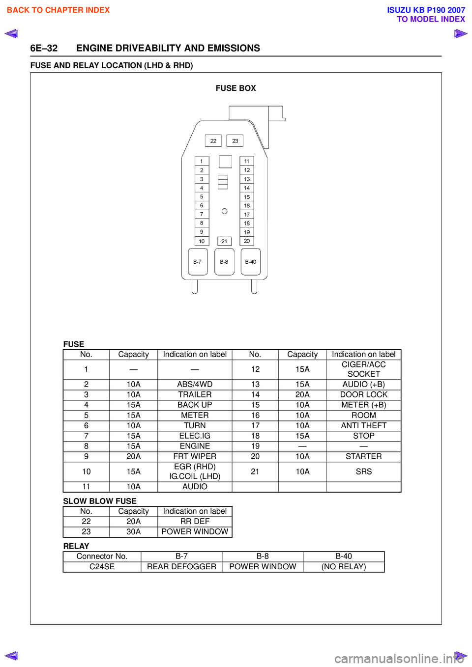
FUSE AND RELAY LOCATION (LHD & RHD)
FUSE
SLOW BLOW FUSE
RELAY No. Capacity Indication on label No. Capacity Indication on label
1— — 1 215A CIGER/ACC
SOCKET
2 10A ABS/4WD 13 15A AUDIO (+B)
3 10A TRAILER 14 20A DOOR LOCK
4 15A BACK UP 15 10A METER (+B)
5 15A METER16 10A ROOM
6 10A TURN17 10A ANTI THEFT
7 15A ELEC.IG 18 15ASTOP
815A ENGINE 19 — —
9 20A FRT WIPER 20 10A STARTER
10 15A EGR (RHD)
IG.COIL (LHD) 21 10A
SRS
11 10A AUDIO
No. Capacity Indication on label 22 20A RR DEF
23 30A POWER WINDOW
Connector No. B-7B-8B-40
C24SE REAR DEFOGGER POWER WINDOW (NO RELAY)
FUSE BOX
BACK TO CHAPTER INDEX
TO MODEL INDEX
ISUZU KB P190 2007
Page 2278 of 6020
6E–108 ENGINE DRIVEABILITY AND EMISSIONS
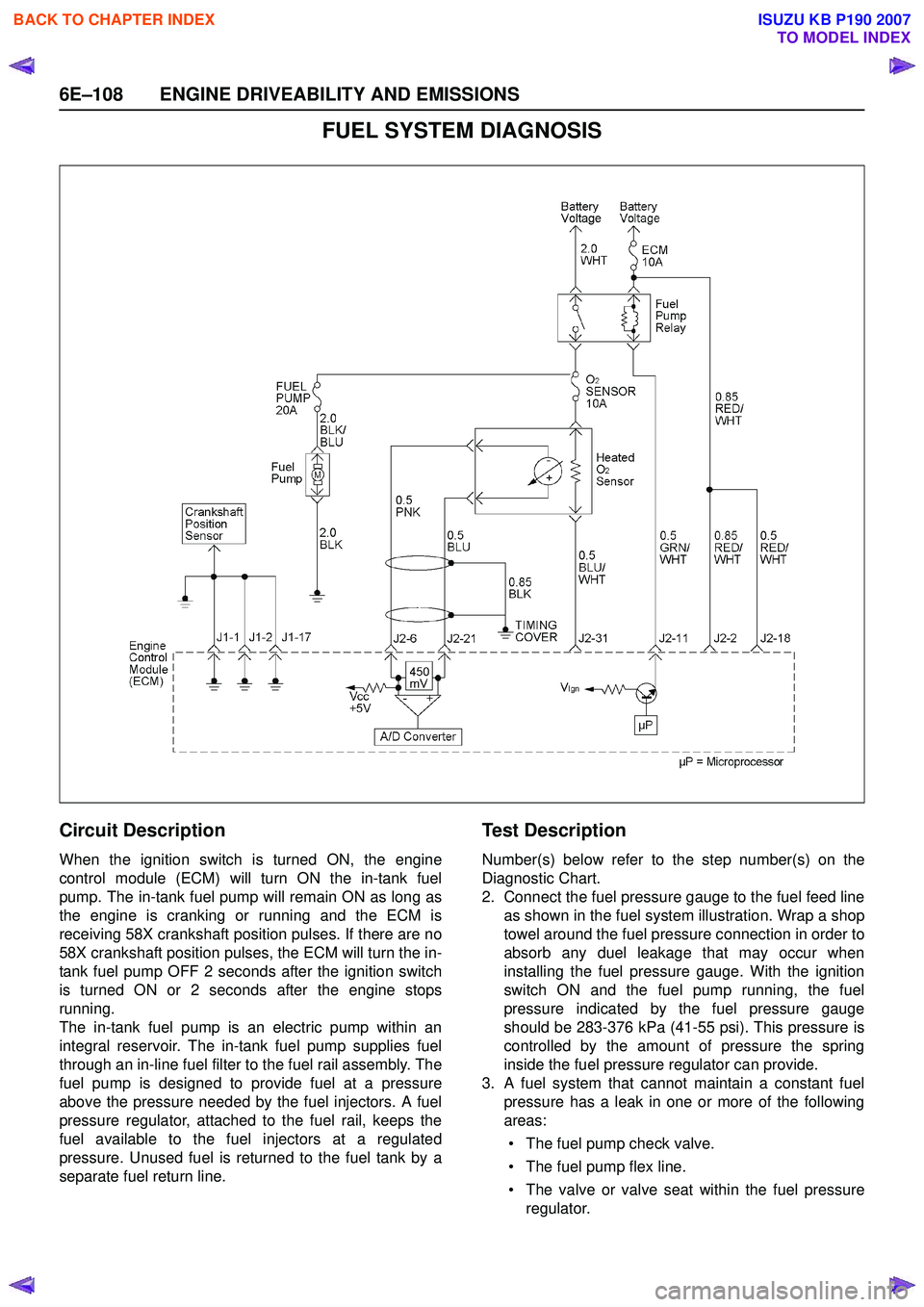
FUEL SYSTEM DIAGNOSIS
Circuit Description
When the ignition switch is turned ON, the engine
control module (ECM) will turn ON the in-tank fuel
pump. The in-tank fuel pump will remain ON as long as
the engine is cranking or running and the ECM is
receiving 58X crankshaft position pulses. If there are no
58X crankshaft position pulses, the ECM will turn the in-
tank fuel pump OFF 2 seconds after the ignition switch
is turned ON or 2 seconds after the engine stops
running.
The in-tank fuel pump is an electric pump within an
integral reservoir. The in-tank fuel pump supplies fuel
through an in-line fuel filter to the fuel rail assembly. The
fuel pump is designed to provide fuel at a pressure
above the pressure needed by the fuel injectors. A fuel
pressure regulator, attached to the fuel rail, keeps the
fuel available to the fuel injectors at a regulated
pressure. Unused fuel is returned to the fuel tank by a
separate fuel return line.
Te s t D e s c r i p t i o n
Number(s) below refer to the step number(s) on the
Diagnostic Chart.
2. Connect the fuel pressure gauge to the fuel feed line as shown in the fuel system illustration. Wrap a shop
towel around the fuel pressure connection in order to
absorb any duel leakage that may occur when
installing the fuel pressure gauge. With the ignition
switch ON and the fuel pump running, the fuel
pressure indicated by the fuel pressure gauge
should be 283-376 kPa (41-55 psi). This pressure is
controlled by the amount of pressure the spring
inside the fuel pressure regulator can provide.
3. A fuel system that cannot maintain a constant fuel pressure has a leak in one or more of the following
areas:
• The fuel pump check valve.
• The fuel pump flex line.
• The valve or valve seat within the fuel pressure regulator.
BACK TO CHAPTER INDEX
TO MODEL INDEX
ISUZU KB P190 2007