Page 1982 of 6020

ENGINE CONTROL SYSTEM (4JK1/4JJ1) 6E-365
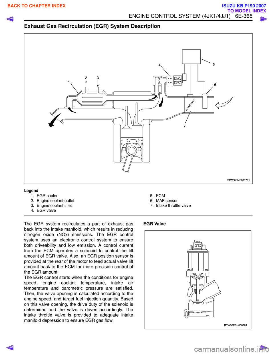
Exhaust Gas Recirculation (EGR) System Description
Legend1. EGR cooler
2. Engine coolant outlet
3. Engine coolant inlet
4. EGR valve 5. ECM
6. MAF sensor
7. Intake throttle valve
The EGR system recirculates a part of exhaust gas
back into the intake manifold, which results in reducing
nitrogen oxide (NOx) emissions. The EGR control
system uses an electronic control system to ensure
both driveability and low emission. A control current
from the ECM operates a solenoid to control the lift
amount of EGR valve. Also, an EGR position sensor is
provided at the rear of the motor to feed actual valve lift
amount back to the ECM for more precision control of
the EGR amount.
The EGR control starts when the conditions for engine
speed, engine coolant temperature, intake air
temperature and barometric pressure are satisfied.
Then, the valve opening is calculated according to the
engine speed, and target fuel injection quantity. Based
on this valve opening, the drive duty of the solenoid is
determined and the valve is driven accordingly. The
intake throttle valve is provided to adequate intake
manifold depression to ensure EGR gas flow. EGR Valve
RTW56EMF001701
1
4
7 5
6
23
RTW56ESH000801
BACK TO CHAPTER INDEX
TO MODEL INDEX
ISUZU KB P190 2007
Page 1983 of 6020

6E-366 ENGINE CONTROL SYSTEM (4JK1/4JJ1)
The EGR valve is mounted on the intake manifold. The
ECM controls the EGR valve opening based on the
engine running condition. The ECM controls the EGR
valve by controlling the solenoid. The solenoid is
controlled based on pulse width modulation (PWM)
signal sent from the ECM. A duty ratio change 0% to
appropriate percentage is EGR valve lift control. To
open the valve, duty ratio is increased. To close the
valve, duty ratio becomes small.
The EGR valve position is detected by the position
sensor, and relayed to the ECM. The position sensor
provides a signal to the ECM on the signal circuit,
which is relative to the position changes of the EGR
valve. The ECM should detect a low signal voltage at a
small lift amount or closed position. The ECM should
detect high signal voltage at a large lift amount.
Intake Throttle Valve
The intake throttle valve is located on the intake
manifold inlet. The ECM controls the intake throttle
valve opening based on the engine running condition.
The ECM controls the intake throttle valve by
controlling the solenoid. The solenoid is controlled
based on pulse width modulation (PWM) signal sent
from the ECM. A duty ratio change 0% to appropriate
percentage is intake throttle valve opening angle
control. To open the valve, duty ratio is increased. To
close the valve, duty ratio becomes small.
The intake throttle valve position is detected by the
position sensor, and relayed to the ECM. The position
sensor provides a signal to the ECM on the signal
circuit, which is relative to the position changes of the
intake throttle valve. The ECM should detect a low
signal voltage at a small opening amount or closed
position. The ECM should detect high signal voltage at
a large opening amount.Turbocharger Description
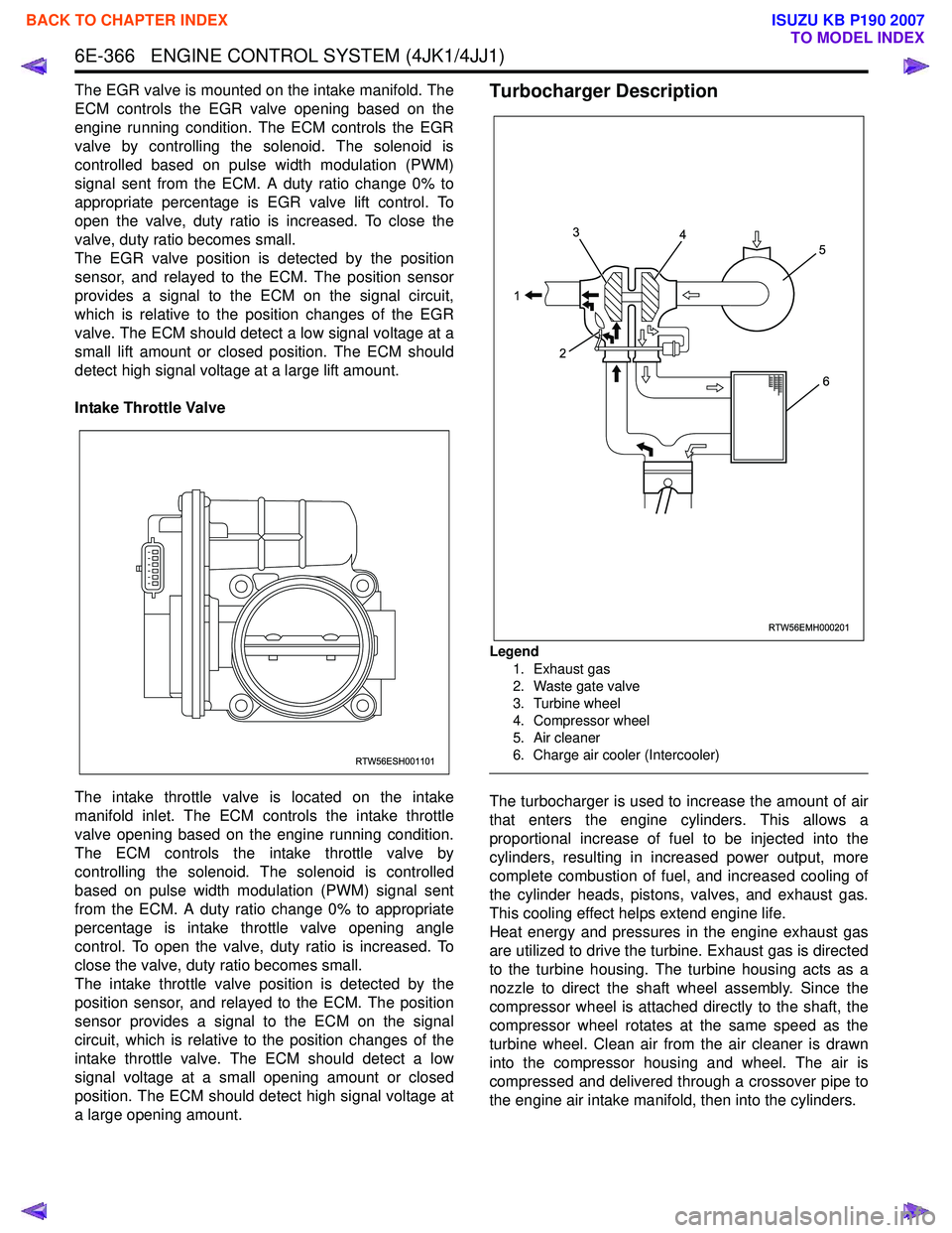
Legend
1. Exhaust gas
2. Waste gate valve
3. Turbine wheel
4. Compressor wheel
5. Air cleaner
6. Charge air cooler (Intercooler)
The turbocharger is used to increase the amount of air
that enters the engine cylinders. This allows a
proportional increase of fuel to be injected into the
cylinders, resulting in increased power output, more
complete combustion of fuel, and increased cooling of
the cylinder heads, pistons, valves, and exhaust gas.
This cooling effect helps extend engine life.
Heat energy and pressures in the engine exhaust gas
are utilized to drive the turbine. Exhaust gas is directed
to the turbine housing. The turbine housing acts as a
nozzle to direct the shaft wheel assembly. Since the
compressor wheel is attached directly to the shaft, the
compressor wheel rotates at the same speed as the
turbine wheel. Clean air from the air cleaner is drawn
into the compressor housing and wheel. The air is
compressed and delivered through a crossover pipe to
the engine air intake manifold, then into the cylinders.
RTW56ESH001101
RTW56EMH000201
1 3
2 4
5
6
BACK TO CHAPTER INDEX
TO MODEL INDEX
ISUZU KB P190 2007
Page 1986 of 6020

EXHAUST SYSTEM (4JK1/4JJ1) 6F-1
SECTION 6F
EXHAUST SYSTEM
CONTENTS
Exhaust Silencer and Exhaust Pipe ................... 6F-2
Main Data and Specifications .......................... 6F-2
Components .................................................... 6F-3
Removal .......................................................... 6F-4
Installation ....................................................... 6F-4
Inspection and Repair ..................................... 6F-5
Torque Specifications...................................... 6F-6
EGR Cooler ........................................................ 6F-7 Components (Standard Output) ...................... 6F-7
Components (High Output) ............................. 6F-8
Removal .......................................................... 6F-9
Installation (Standard Output) ......................... 6F-9
Installation (High Output)................................. 6F-10
Torque Specifications (Standard Output) ........ 6F-11
Torque Specifications (High Output) ............... 6F-12
BACK TO CHAPTER INDEX
TO MODEL INDEX
ISUZU KB P190 2007
Page 1992 of 6020
EXHAUST SYSTEM (4JK1/4JJ1) 6F-7
EGR Cooler
Components (Standard Output)
RTW 56FMF000101
Legend
1. EGR Cooler
2. Gasket
3. Gasket
4. Bolt
5. W asher
6. Heat Protector
7. W ater Hose Intake
8. W ater Hose Return
9. Bolt
10. Nut
BACK TO CHAPTER INDEX
TO MODEL INDEX
ISUZU KB P190 2007
Page 1993 of 6020
6F-8 EXHAUST SYSTEM (4JK1/4JJ1)
Components (High Output)
RTW 76FMF000101
Legend
1. EGR Cooler
2. EGR Cooler Gasket
3. EGR Cooler Gasket
4. Heat Protector
5. Exhaust Manifold
BACK TO CHAPTER INDEX
TO MODEL INDEX
ISUZU KB P190 2007
Page 1994 of 6020
EXHAUST SYSTEM (4JK1/4JJ1) 6F-9
Removal
1. Drain the coolant.
2. Remove the intercooler.
3. Remove the heat protector.
4. Disconnect the water hoses from the EGR coole
r
water pipes.
5. Remove the EGR cooler.
Installation (Standard Output)
1. Gasket
2. EGR Cooler
3. Nuts and Bolts
RTW 56FSH000201
• Temporary tightening order
1 – 2 – 4 – 5 - 3
• Fully tightening order
4 – 5 – 1 – 2 - 3
Tighten the nuts and bolts to the specified torque.
Tightening torque: 27 N ⋅
⋅⋅
⋅
m (2.8 kg ⋅
⋅⋅
⋅
m / 20 lb ft)
4. W ater hose
5. Heat protector • Tighten the bolts to the specified torque.
Tightening torque: 10 N ⋅
⋅⋅
⋅
m (1.0 kg ⋅
⋅⋅
⋅
m / 87 lb in)
RTW 56ASH014601
6. Replenish the engine coolant.
BACK TO CHAPTER INDEX
TO MODEL INDEX
ISUZU KB P190 2007
Page 1995 of 6020
6F-10 EXHAUST SYSTEM (4JK1/4JJ1)
Installation (High Output)
1. Gasket
2. EGR Cooler
3. Nuts and Bolts
6
543
1
2
RTW 76FSH000201
• Temporary tightening order
1 →2→ 3→ 4→ 5→ 6
• Fully tightening order
3 →4→ 5→ 1→ 2→ 6
Tighten the nuts and bolts to the specified torque.
Tightening torque: Nuts and bolts 1-5: 27 N ⋅
⋅⋅
⋅
m (2.8 kg ⋅
⋅⋅
⋅
m / 20 lb ft)
Bolt 6: 52 N⋅
⋅⋅
⋅
m (5.3 kg ⋅
⋅⋅
⋅
m / 38 lb ft)
4. W ater hose
5. Heat protector • Tighten the bolts to the specified torque.
Tightening torque: 25 N ⋅
⋅⋅
⋅
m (2.5 kg ⋅
⋅⋅
⋅
m / 18 lb ft)
RTW 76FSH000101
6. Replenish the engine coolant.
BACK TO CHAPTER INDEX
TO MODEL INDEX
ISUZU KB P190 2007
Page 2008 of 6020

6-8 ENGINE DIAGNOSIS (C24SE)
Condition Possible cause Correction
Engine overheating Level of Engine Coolant too low Replenish
Thermo switch or fan motor
defective Replace
Thermostat
defective Replace
Engine Coolant pump defective Correct or replace
Radiator clogged Clean or replace
Radiator filter cap defective Replace
Level of oil in engine crankcase
too low or wrong oil in engine Change or replenish
Resistance in exhaust system
increased Clean exhaust system or replace
defective parts
Throttle Position Sensor
adjustment incorrect Adjust Wide Open Throttle switch
setting
Throttle Position Sensor circuit
open or shorted Correct or replace
Cylinder head gasket damaged Replace
Cooling Fan clutch defective Replace
Fan belt slipping Adjust tension of V-belt or replace
V-belt
Engine overcooling Thermostat defective Replace (Use a thermostat set to
open at 92 °C (197.6 °F))
Engine lacks compression - Refer to Hard Start
Others Tire inflation pressure abnormal Adjust to recommend pressures
Brake drag Adjust
Clutch slipping Adjust or replace
Level of oil in engine crankcase
too high Correct level of engine oil
Engine Noisy
Abnormal engine noise often consists of various
noises originating in rotating parts, sliding parts and
other moving parts of the engine. It is, therefore,
advisable to locate the source of noise systematically.
Condition Possible cause Correction
Noise from crank journals or from
crank bearings
(Faulty crank journals and crank
bearings usually make dull noise
that becomes more evident when
accelerating) Oil clearance increased due to
worn crank journals or crank
bearings Replace crank bearings and
crankshaft or regrind crankshaft
and install the over size bearing
Crankshaft out of round Replace crank bearings and
crankshaft or regrind crankshaft
and install the over size bearing
Crank bearing seized Replace crank bearings and
crankshaft or regrind crankshaft
and install the over size bearing
BACK TO CHAPTER INDEX
TO MODEL INDEX
ISUZU KB P190 2007