2007 ISUZU KB P190 EGR
[x] Cancel search: EGRPage 2286 of 6020
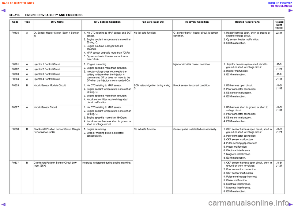
6E–116 ENGINE DRIVEABILITY AND EMISSIONSP0135 A O
2 Sensor Heater Circuit (Bank 1 Sensor
1) 1. No DTC relating to MAP sensor and ECT
sensor.
2. Engine coolant temperature is more than 60 deg. C.
3. Engine run time is longer than 20 seconds.
4. MAP sensor output is more than 70kPa.
5. O
2 sensor bank 1 heater current more
than 10mA. No fail-safe function.
O
2 sensor bank 1 heater circuit is correct
condition. 1. Heater harness open, short to ground or
short to voltage circuit.
2. O
2 sensor heater malfunction.
3. ECM malfunction. J2-31
P0201 A Injector 1 Control Circuit 1. Engine is running. 2. Engine speed is more than 1000rpm.
3. Injector voltage does not meet to the battery voltage when the injector is
commanded Off or does not meet to the
0V when the injector is commanded On. Injector circuit is correct condition.
1. Injector harness open circuit, short to
ground or short to voltage circuit.
2. Injector malfunction.
3. ECM malfunction. J1-9
P0202 A Injector 2 Control Circuit J1-22
P0203 A Injector 3 Control Circuit J1-8
P0204 A Injector 4 Control Circuit J1-11
P0325 B Knock Sensor Module Circuit 1. No DTC relating to MAP sensor.
2. Engine coolant temperature is more than 50 deg. C.
3. Engine speed is more than 1600rpm.
4. Knock sensor filter module integrated circuit malfunction. ECM retards ignition timing 4 deg.
C . Knock sensor is correct condition.
1. KS harness open circuit.
2. Poor connector connection.
3. KS sensor malfunction.
4. ECM malfunction. J1-3/
J1-32
P0327 A Knock Sensor Circuit 1. No DTC relating to MAP sensor.
2. Engine coolant temperature is more than 50 deg. C.
3. Engine speed is more than 1600rpm.
4. Knock sensor harness short to ground or short to voltage circuit. 1. KS harness short to ground or short to
voltage circuit.
2. Poor connector connection.
3. KS sensor malfunction.
4. ECM malfunction. J1-3/
J1-32
P0336 B Crankshaft Position Sensor Circuit Range/ Performance (58X) 1. Engine is running.
2. Extra or missing pulse is detected consecutively. No fail-safe function.
Correct pulse is detected consecutively. 1. CKP sensor harness open circuit, short to
ground or short to voltage circuit.
2. Poor connector connection.
3. CKP sensor malfunction.
4. Pulse sensing gap incorrect.
5. Pluser malfunction.
6. Electrical interference.
7. Magnetic interference.
8. ECM malfunction. J1-6/
J1-21
P0337 B Crankshaft Position Sensor Circuit Low Input (58X) No pulse is detected during engine cranking.
1. CKP sensor harness open circuit, short to
ground or short to voltage.
2. Poor connector connection.
3. CKP sensor malfunction.
4. Pulse sensing gap incorrect.
5. Pluser malfunction.
6. Electrical interference.
7. Magnetic interference.
8. ECM malfunction. J1-6/
J1-21
Code Type
DTC Name DTC Setting Condition Fail-Safe (Back Up)Recovery Condition Related Failure PartsRelated
ECM
Pin No.
BACK TO CHAPTER INDEX
TO MODEL INDEX
ISUZU KB P190 2007
Page 2322 of 6020
6E–152 ENGINE DRIVEABILITY AND EMISSIONS
• Poor ECM to engine block grounds.
• Fuel pressure - The system will go lean if pressure is too low. The ECM can compensate for some
decrease. However, if fuel pressure is too low, a
Diagnostic Trouble Code P0131 may be set. Refer to
Fuel System Diagnosis.
• Lean injector(s) - Perform “Injector Balance Test.”
• Vacuum leaks - Check for disconnected or damaged vacuum hoses and for vacuum leaks at the intake
manifold, throttle body, EGR system, and PCV
system. • Exhaust leaks - An exhaust leak may cause outside
air to be pulled into the exhaust gas stream past the
HO2S, causing the system to appear lean. Check for
exhaust leaks that may cause a false lean condition
to be indicated.
• Fuel contamination - Water, even in small amounts, can be delivered to the fuel injectors. The water can
cause a lean exhaust to be indicated. Excessive
alcohol in the fuel can also cause this condition. For
the procedure to check for fuel contamination, Refer
to Fuel System Diagnosis.
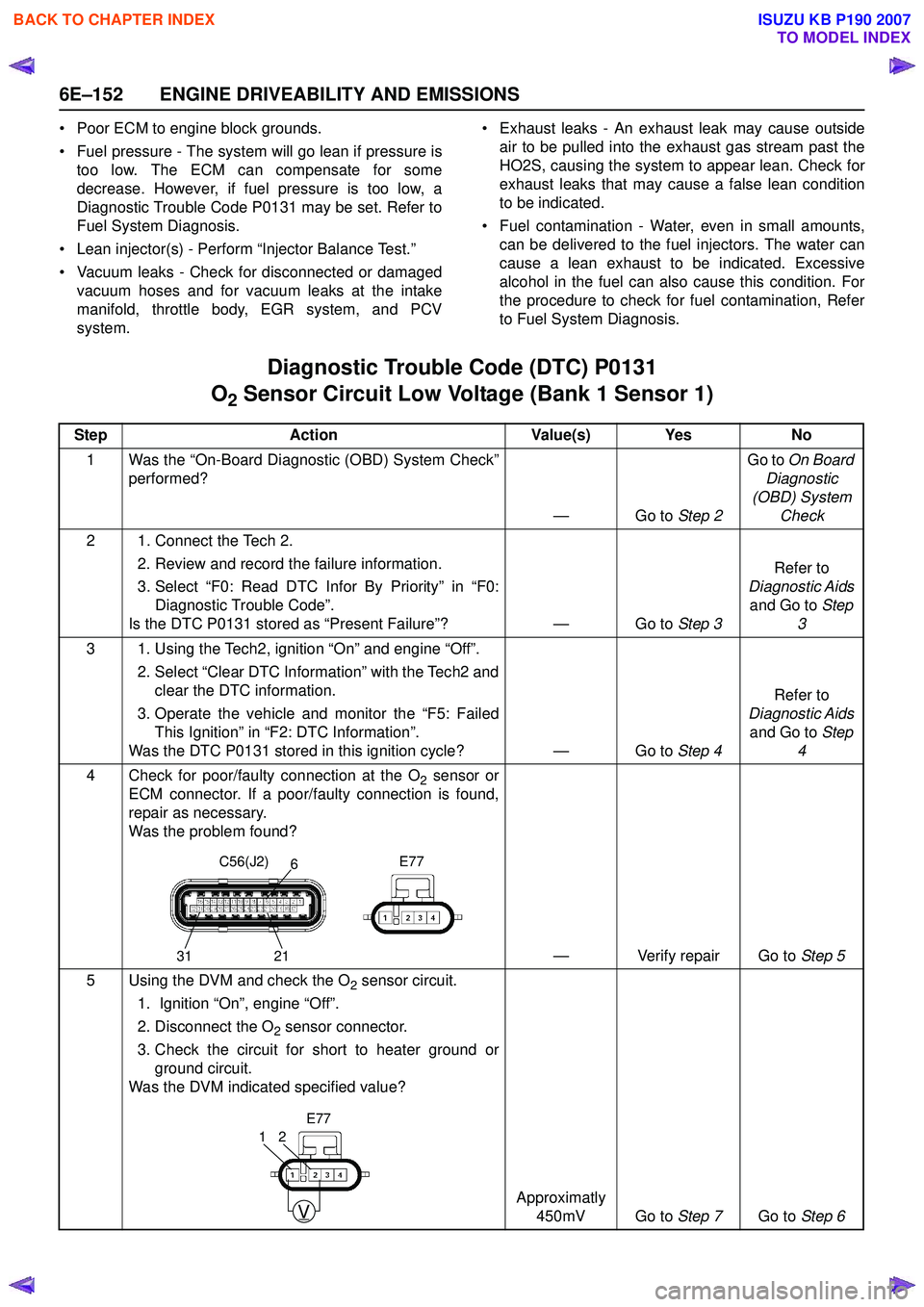
Diagnostic Trouble Code (DTC) P0131
O
2 Sensor Circuit Low Voltage (Bank 1 Sensor 1)
Step Action Value(s) Yes No
1 Was the “On-Board Diagnostic (OBD) System Check” performed?
—Go to Step 2Go to
On Board
Diagnostic
(OBD) System Check
2 1. Connect the Tech 2. 2. Review and record the failure information.
3. Select “F0: Read DTC Infor By Priority” in “F0: Diagnostic Trouble Code”.
Is the DTC P0131 stored as “Present Failure”? — Go to Step 3Refer to
Diagnostic Aids and Go to Step
3
3 1. Using the Tech2, ignition “On” and engine “Off”. 2. Select “Clear DTC Information” with the Tech2 andclear the DTC information.
3. Operate the vehicle and monitor the “F5: Failed This Ignition” in “F2: DTC Information”.
Was the DTC P0131 stored in this ignition cycle? — Go to Step 4Refer to
Diagnostic Aids and Go to Step
4
4 Check for poor/faulty connection at the O
2 sensor or
ECM connector. If a poor/faulty connection is found,
repair as necessary.
Was the problem found?
— Verify repair Go to Step 5
5 Using the DVM and check the O
2 sensor circuit.
1. Ignition “On”, engine “Off”.
2. Disconnect the O
2 sensor connector.
3. Check the circuit for short to heater ground or ground circuit.
Was the DVM indicated specified value?
Approximatly 450mV Go to Step 7Go to Step 6
C56(J2) E77
31 216
V
21
E77
BACK TO CHAPTER INDEX
TO MODEL INDEX
ISUZU KB P190 2007
Page 2344 of 6020
6E–174 ENGINE DRIVEABILITY AND EMISSIONS
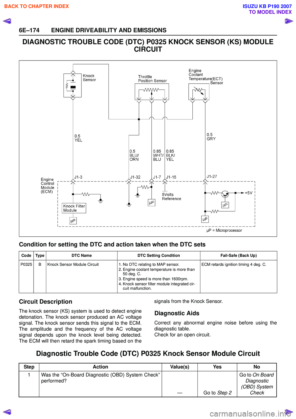
DIAGNOSTIC TROUBLE CODE (DTC) P0325 KNOCK SENSOR (KS) MODULE CIRCUIT
Condition for setting the DTC and action taken when the DTC sets
Circuit Description
The knock sensor (KS) system is used to detect engine
detonation. The knock sensor produced an AC voltage
signal. The knock sensor sends this signal to the ECM.
The amplitude and the frequency of the AC voltage
signal depends upon the knock level being detected.
The ECM will then retard the spark timing based on the signals from the Knock Sensor.Diagnostic Aids
Correct any abnormal engine noise before using the
diagnostic table.
Check for an open circuit.
Diagnostic Trouble Code (DTC) P0325 Knock Sensor Module Circuit
Code Type DTC Name DTC Setting Condition Fail-Safe (Back Up)
P0325 B Knock Sensor Module Circuit 1. No DTC relating to MAP sensor.
2. Engine coolant temperature is more than 50 deg. C.
3. Engine speed is more than 1600rpm.
4. Knock sensor filter module integrated cir- cuit malfunction. ECM retards ignition timing 4 deg. C
.
StepAction Value(s) Yes No
1 Was the “On-Board Diagnostic (OBD) System Check” performed?
—Go to Step 2Go to
On Board
Diagnostic
(OBD) System Check
BACK TO CHAPTER INDEX
TO MODEL INDEX
ISUZU KB P190 2007
Page 2415 of 6020
ENGINE DRIVEABILITY AND EMISSIONS 6E–245
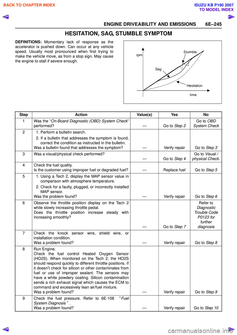
HESITATION, SAG, STUMBLE SYMPTOM
DEFINITIONS: Momentary lack of response as the
accelerator is pushed down. Can occur at any vehicle
speed. Usually most pronounced when first trying to
make the vehicle move, as from a stop sign. May cause
the engine to stall if severe enough.
Step Action Value(s) Yes No
1 Was the “ On-Board Diagnostic (OBD) System Check ”
performed? — Go to Step 2Go to
OBD
System Check
2 1. Perform a bulletin search. 2. If a bulletin that addresses the symptom is found,correct the condition as instructed in the bulletin.
Was a bulletin found that addresses the symptom? — Verify repair Go to Step 3
3 Was a visual/physical check performed? —Go to Step 4Go to
Visual /
physical Check .
4 Check the fuel quality. Is the customer using improper fuel or degraded fuel? — Replace fuel Go to Step 5
5 1. Using a Tech 2, display the MAP sensor value in comparison with atmosphere temperature.
2. Check for a faulty, plugged, or incorrectly installed MAP sensor.
Was the problem found? — Verify repair Go to Step 6
6 Observe the throttle position display on the Tech 2 while slowly increasing throttle pedal.
Does the throttle position increase steady with
increasing smoothly?
—Go to Step 7Refer to
Diagnostic
Trouble Code P0123 for further
diagnosis
7 Check the knock sensor wire, shield wire, or installation condition.
Was a problem found? — Verify repair Go to Step 8
8 Run Engine. Check the fuel control Heated Oxygen Sensor
(HO2S). When monitored on the Tech 2, the HO2S
should respond quickly to different throttle positions. If
it doesn’t check for silicon or other contaminates from
fuel or use of improper sealant. The sensors may
have a white powdery coating. Silicon contamination
sends a rich exhaust signal which causes the ECM to
command and excessively lean air/fuel mixture.
Was a problem found? — Verify repair Go to Step 9
9 Check the fuel pressure. Refer to 6E-108 “Fuel
System Diagnosis
”.
Was a problem found? — Verify repair Go to Step 10
BACK TO CHAPTER INDEX
TO MODEL INDEX
ISUZU KB P190 2007
Page 2487 of 6020
Engine Mechanical – V6 Page 6A1–8
1 General Information
The HFV6 engine features a closed vee, deep skirt die cast aluminium cylinder block with cast iron cylinder liners,
internally balanced crankcase, full length water jackets and six bolt main bearing caps.
The cylinders are arranged in two banks of three with a 60 degree included angle between the two banks.
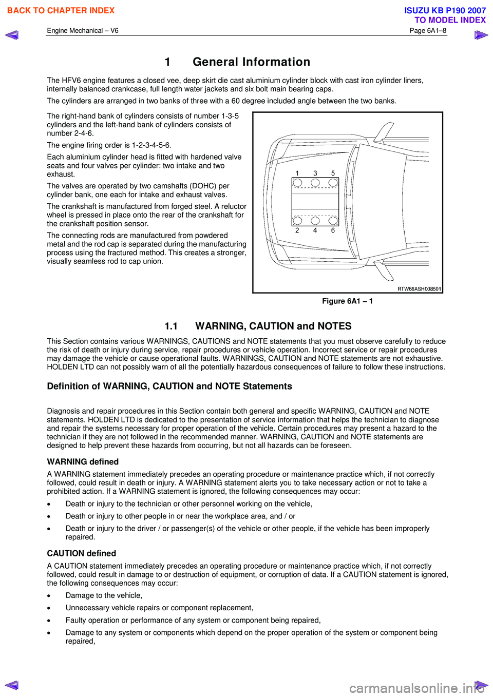
The right-hand bank of cylinders consists of number 1-3-5
cylinders and the left-hand bank of cylinders consists of
number 2-4-6.
The engine firing order is 1-2-3-4-5-6.
Each aluminium cylinder head is fitted with hardened valve
seats and four valves per cylinder: two intake and two
exhaust.
The valves are operated by two camshafts (DOHC) per
cylinder bank, one each for intake and exhaust valves.
The crankshaft is manufactured from forged steel. A reluctor
wheel is pressed in place onto the rear of the crankshaft for
the crankshaft position sensor.
The connecting rods are manufactured from powdered
metal and the rod cap is separated during the manufacturing
process using the fractured method. This creates a stronger,
visually seamless rod to cap union.
Figure 6A1 – 1
1.1 WARNING, CAUTION and NOTES
This Section contains various W ARNINGS, CAUTIONS and NOTE statements that you must observe carefully to reduce
the risk of death or injury during service, repair procedures or vehicle operation. Incorrect service or repair procedures
may damage the vehicle or cause operational faults. W ARNINGS, CAUTION and NOTE statements are not exhaustive.
HOLDEN LTD can not possibly warn of all the potentially hazardous consequences of failure to follow these instructions.
Definition of WARNING, CAUTION and NOTE Statements
Diagnosis and repair procedures in this Section contain both general and specific W ARNING, CAUTION and NOTE
statements. HOLDEN LTD is dedicated to the presentation of service information that helps the technician to diagnose
and repair the systems necessary for proper operation of the vehicle. Certain procedures may present a hazard to the
technician if they are not followed in the recommended manner. W ARNING, CAUTION and NOTE statements are
designed to help prevent these hazards from occurring, but not all hazards can be foreseen.
WARNING defined
A W ARNING statement immediately precedes an operating procedure or maintenance practice which, if not correctly
followed, could result in death or injury. A W ARNING statement alerts you to take necessary action or not to take a
prohibited action. If a W ARNING statement is ignored, the following consequences may occur:
• Death or injury to the technician or other personnel working on the vehicle,
• Death or injury to other people in or near the workplace area, and / or
• Death or injury to the driver / or passenger(s) of the vehicle or other people, if the vehicle has been improperly
repaired.
CAUTION defined
A CAUTION statement immediately precedes an operating procedure or maintenance practice which, if not correctly
followed, could result in damage to or destruction of equipment, or corruption of data. If a CAUTION statement is ignored,
the following consequences may occur:
• Damage to the vehicle,
• Unnecessary vehicle repairs or component replacement,
• Faulty operation or performance of any system or component being repaired,
• Damage to any system or components which depend on the proper operation of the system or component being
repaired,
BACK TO CHAPTER INDEX
TO MODEL INDEX
ISUZU KB P190 2007
Page 2501 of 6020

Engine Mechanical – V6 Page 6A1–22
Crankshaft
The crankshaft is a forged steel design with four main bearings. The number three main bearing controls crankshaft
thrust. A crankshaft position reluctor wheel is pressed onto the rear of the crankshaft, in front of the rear main journal.
The crankshaft is internally balanced with an integral oil pump drive machined into the nose in front of the front main
journal.
Pistons, Pins and Connecting Rods
The piston assembly (1) is fitted with two low tension
compression rings and one multi-piece oil control ring. The
top compression ring is plasma sprayed, while the second
compression ring is cast iron Napier.
The oil control ring incorporates a steel expander and two
chrome plated steel rails.
The connecting rods are sinter forged steel and have full
floating piston pins. The piston pins are a slip-fit type, into
the bronze bushed connecting rods. Round wire retainers
are used to retain the piston pin into the piston.
The cast aluminium pistons incorporate a polymer coated
skirt to reduce friction.
Figure 6A1 – 17
Camshaft Drive System
Three timing chains are fitted:
• primary (1),
• right-hand secondary (2), and
• left-hand secondary (3), refer to Figure 6A1 – 18 for the HFV6 engine.
The primary timing chain connects the crankshaft sprocket (4) with the left-hand and right-hand intermediate drive shaft
sprockets (5).
Each oil pressure fed intermediate sprocket drives the secondary timing chains, which subsequently drive the respective
cylinder head camshaft position actuators (6).
Two stationary timing chain guides (7) and movable timing chain shoes (8) control secondary timing chain backlash.
Each secondary timing chain shoe is under tension from an oil pressure hydraulically operated tensioner (9). To control
backlash on the primary chain, two stationary timing chain guides (10) and an oil pressure hydraulically actuated
tensioner with built in shoe (11) are fitted.
The tensioners minimise timing chain noise and provide accurate valve action by keeping slack out of the timing chains,
while continuously adjusting for timing chain wear. The tensioners incorporate a plunger that adjusts outward with wear,
minimising backlash. The tensioners are equipped with oiling jets to spray oil onto the timing components during engine
operation. Each tensioner is sealed to the head or block using a rubber coated steel gasket. The gasket traps an
adequate oil reserve to ensure quiet start-up.
BACK TO CHAPTER INDEX
TO MODEL INDEX
ISUZU KB P190 2007
Page 2591 of 6020
Engine Mechanical – V6 Page 6A1–112
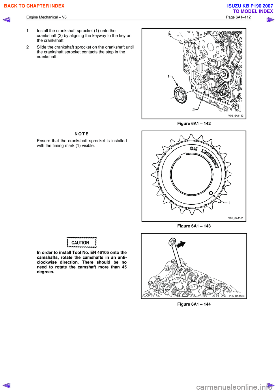
1 Install the crankshaft sprocket (1) onto the
crankshaft (2) by aligning the keyway to the key on
the crankshaft.
2 Slide the crankshaft sprocket on the crankshaft until the crankshaft sprocket contacts the step in the
crankshaft.
Figure 6A1 – 142
NOTE
Ensure that the crankshaft sprocket is installed
with the timing mark (1) visible.
Figure 6A1 – 143
CAUTION
In order to install Tool No. EN 46105 onto the
camshafts, rotate the camshafts in an anti-
clockwise direction. There should be no
need to rotate the camshaft more than 45
degrees.
Figure 6A1 – 144
BACK TO CHAPTER INDEX
TO MODEL INDEX
ISUZU KB P190 2007
Page 2608 of 6020
Engine Mechanical – V6 Page 6A1–129
CAUTION
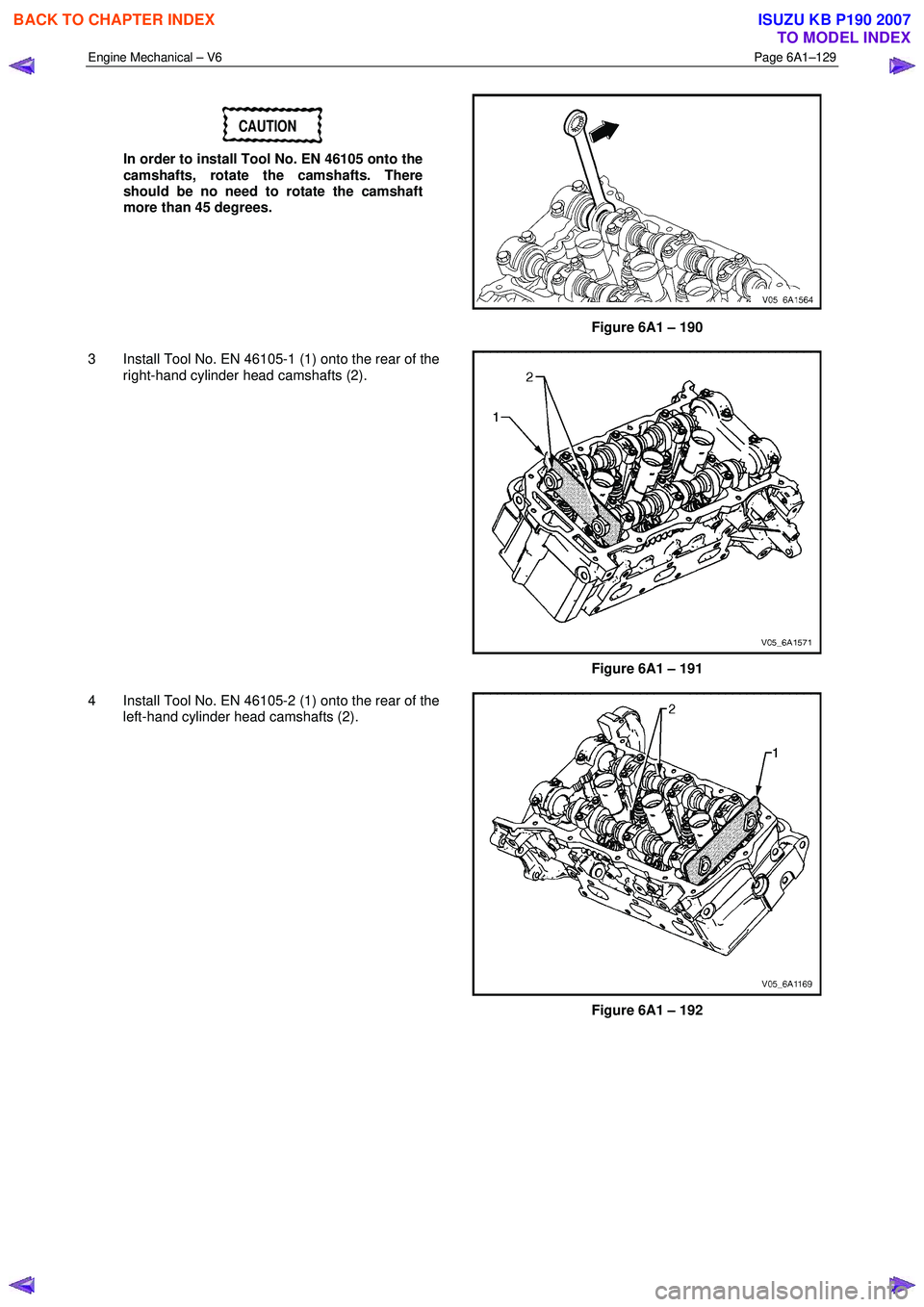
In order to install Tool No. EN 46105 onto the
camshafts, rotate the camshafts. There
should be no need to rotate the camshaft
more than 45 degrees.
Figure 6A1 – 190
3 Install Tool No. EN 46105-1 (1) onto the rear of the right-hand cylinder head camshafts (2).
Figure 6A1 – 191
4 Install Tool No. EN 46105-2 (1) onto the rear of the left-hand cylinder head camshafts (2).
Figure 6A1 – 192
BACK TO CHAPTER INDEX
TO MODEL INDEX
ISUZU KB P190 2007