2007 ISUZU KB P190 EGR
[x] Cancel search: EGRPage 2907 of 6020
Engine Mechanical – V6 Page 6A1–130
Page 6A1–130
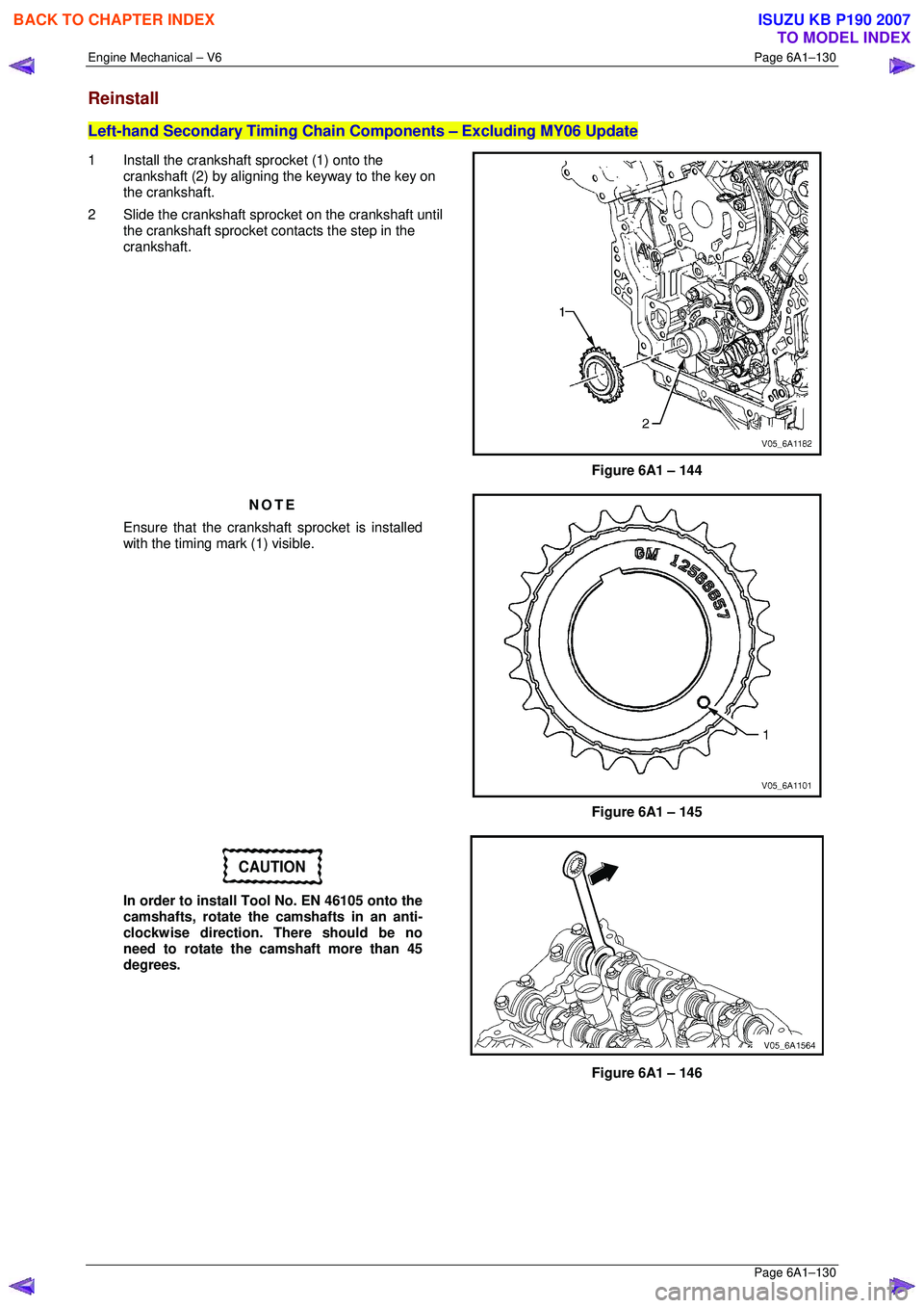
Reinstall
Left-hand Secondary Timing Chain Components – Excluding MY06 Update
1 Install the crankshaft sprocket (1) onto the
crankshaft (2) by aligning the keyway to the key on
the crankshaft.
2 Slide the crankshaft sprocket on the crankshaft until the crankshaft sprocket contacts the step in the
crankshaft.
Figure 6A1 – 144
NOTE
Ensure that the crankshaft sprocket is installed
with the timing mark (1) visible.
Figure 6A1 – 145
CAUTION
In order to install Tool No. EN 46105 onto the
camshafts, rotate the camshafts in an anti-
clockwise direction. There should be no
need to rotate the camshaft more than 45
degrees.
Figure 6A1 – 146
BACK TO CHAPTER INDEX
TO MODEL INDEX
ISUZU KB P190 2007
Page 2917 of 6020
Engine Mechanical – V6 Page 6A1–140
Page 6A1–140
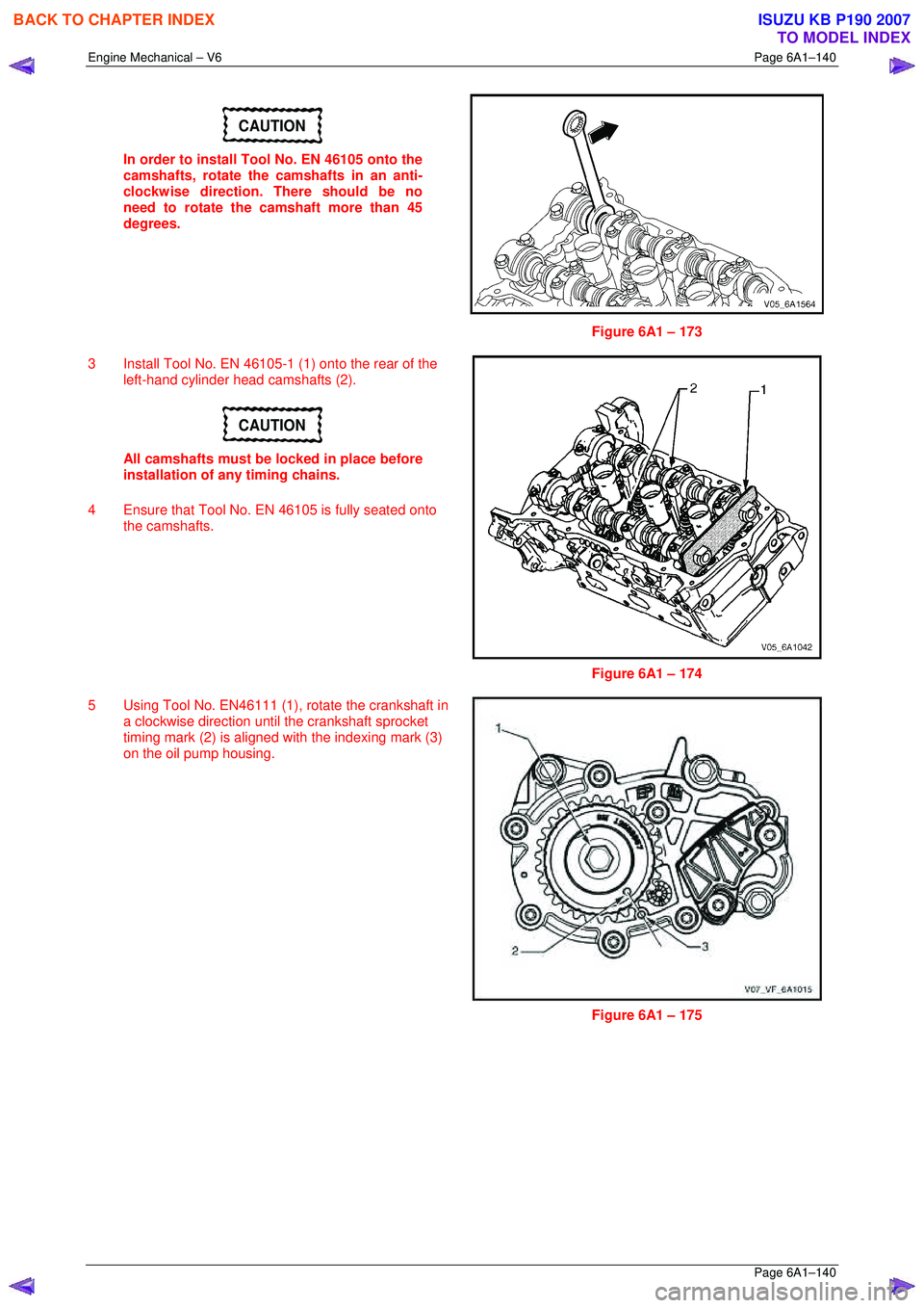
CAUTION
In order to install Tool No. EN 46105 onto the
camshafts, rotate the camshafts in an anti-
clockwise direction. There should be no
need to rotate the camshaft more than 45
degrees.
Figure 6A1 – 173
3 Install Tool No. EN 46105-1 (1) onto the rear of the
left-hand cylinder head camshafts (2).
CAUTION
All camshafts must be locked in place before
installation of any timing chains.
4 Ensure that Tool No. EN 46105 is fully seated onto the camshafts.
Figure 6A1 – 174
5 Using Tool No. EN46111 (1), rotate the crankshaft in a clockwise direction until the crankshaft sprocket
timing mark (2) is aligned with the indexing mark (3)
on the oil pump housing.
Figure 6A1 – 175
BACK TO CHAPTER INDEX
TO MODEL INDEX
ISUZU KB P190 2007
Page 2941 of 6020
Engine Mechanical – V6 Page 6A1–164
Page 6A1–164
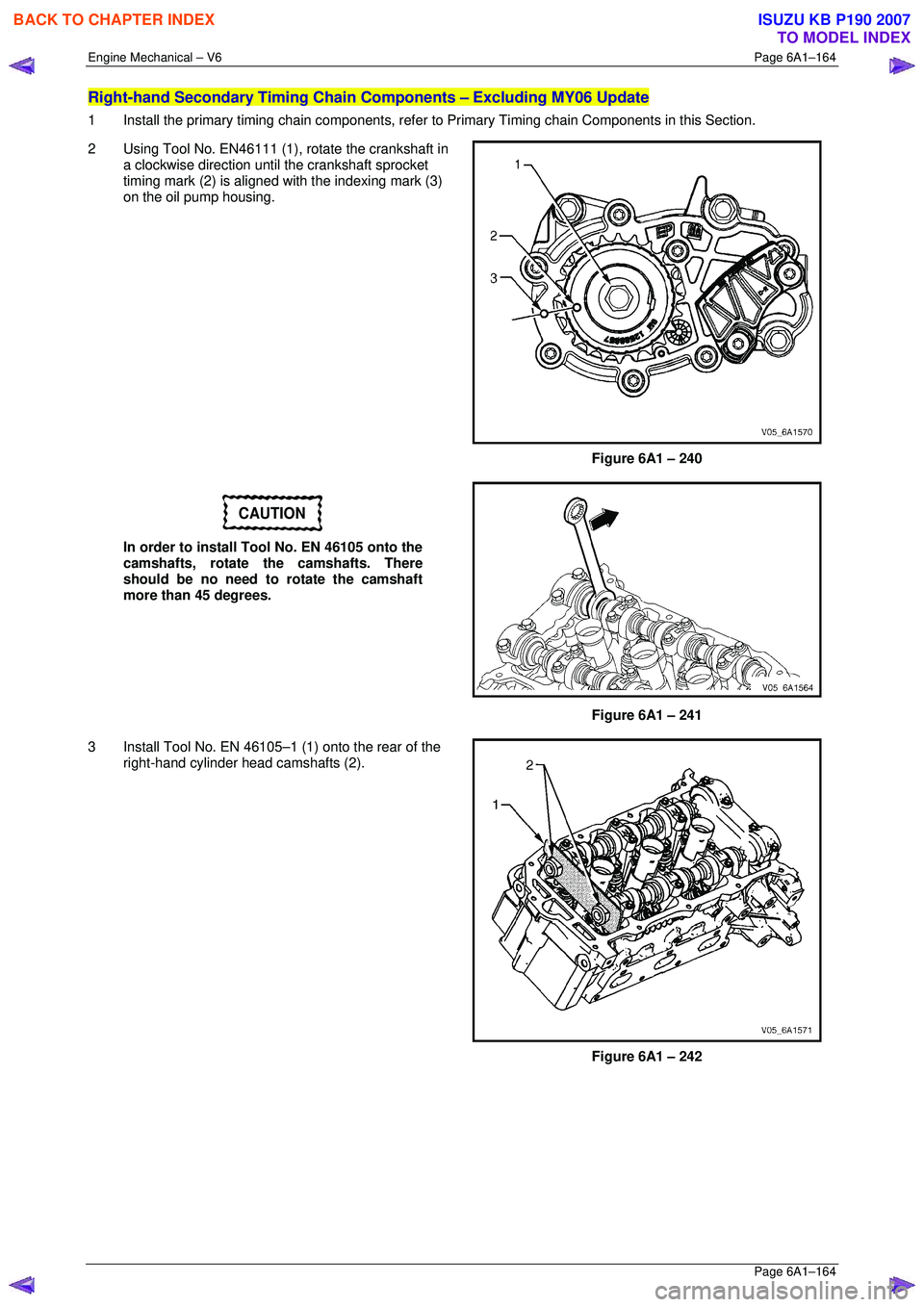
Right-hand Secondary Timing Chain Components – Excluding MY06 Update
1 Install the primary timing chain components, refer to Primary Timing chain Components in this Section.
2 Using Tool No. EN46111 (1), rotate the crankshaft in a clockwise direction until the crankshaft sprocket
timing mark (2) is aligned with the indexing mark (3)
on the oil pump housing.
Figure 6A1 – 240
CAUTION
In order to install Tool No. EN 46105 onto the
camshafts, rotate the camshafts. There
should be no need to rotate the camshaft
more than 45 degrees.
Figure 6A1 – 241
3 Install Tool No. EN 46105–1 (1) onto the rear of the right-hand cylinder head camshafts (2).
Figure 6A1 – 242
BACK TO CHAPTER INDEX
TO MODEL INDEX
ISUZU KB P190 2007
Page 2949 of 6020
Engine Mechanical – V6 Page 6A1–172
Page 6A1–172
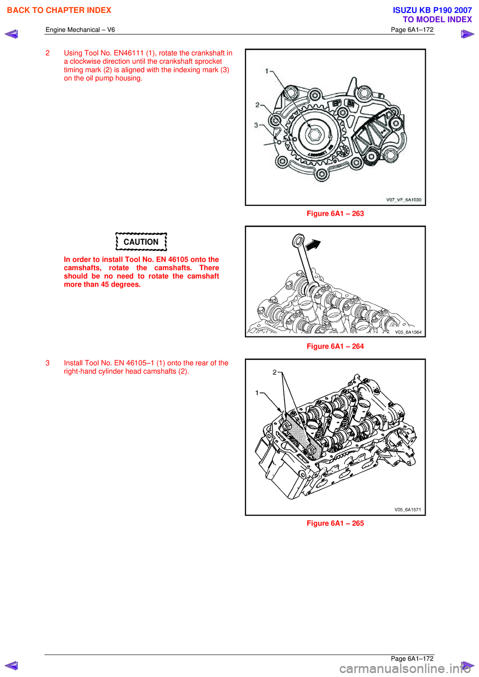
2 Using Tool No. EN46111 (1), rotate the crankshaft in
a clockwise direction until the crankshaft sprocket
timing mark (2) is aligned with the indexing mark (3)
on the oil pump housing.
Figure 6A1 – 263
CAUTION
In order to install Tool No. EN 46105 onto the
camshafts, rotate the camshafts. There
should be no need to rotate the camshaft
more than 45 degrees.
Figure 6A1 – 264
3 Install Tool No. EN 46105–1 (1) onto the rear of the right-hand cylinder head camshafts (2).
Figure 6A1 – 265
BACK TO CHAPTER INDEX
TO MODEL INDEX
ISUZU KB P190 2007
Page 2999 of 6020
Engine Mechanical – V6 Page 6A1–222
Page 6A1–222
Clean
CAUTION
Due to the aluminium alloy construction of
the cylinder head, wire brushes and steel
scrapers must not be used during the
cleaning process, as damage to sealing
surfaces may occur. Use a wood or plastic
scraper as an alternative.
1 Remove any old thread sealant, gasket material or seal ant using commercially available plastic or wooden scraper.
2 Clean all cylinder head surfaces with non-corrosive solvent.
Safety glasses must be worn when using
compressed air.
3 Blow out all the oil galleries using compressed air.
4 Remove any carbon deposits fr om the combustion chambers.
5 Clean any debris or build-up from the lifter pockets.
Inspect
Visual Inspection
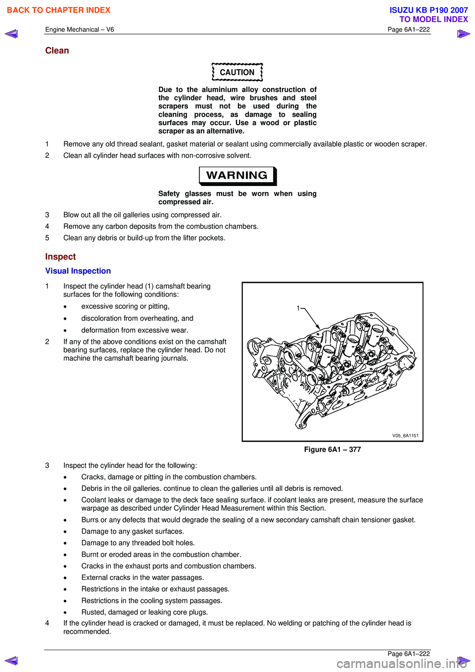
1 Inspect the cylinder head (1) camshaft bearing surfaces for the following conditions:
• excessive scoring or pitting,
• discoloration from overheating, and
• deformation from excessive wear.
2 If any of the above conditions exist on the camshaft bearing surfaces, replace the cylinder head. Do not
machine the camshaft bearing journals.
Figure 6A1 – 377
3 Inspect the cylinder head for the following: • Cracks, damage or pitting in the combustion chambers.
• Debris in the oil galleries. continue to cl ean the galleries until all debris is removed.
• Coolant leaks or damage to the deck face sealing surfac e. if coolant leaks are present, measure the surface
warpage as described under Cylinder Head M easurement within this Section.
• Burrs or any defects that would degrade the sealing of a new secondar y camshaft chain tensioner gasket.
• Damage to any gasket surfaces.
• Damage to any threaded bolt holes.
• Burnt or eroded areas in the combustion chamber.
• Cracks in the exhaust ports and combustion chambers.
• External cracks in the water passages.
• Restrictions in the intake or exhaust passages.
• Restrictions in the cooling system passages.
• Rusted, damaged or leaking core plugs.
4 If the cylinder head is cracked or damaged, it must be r eplaced. No welding or patching of the cylinder head is
recommended.
BACK TO CHAPTER INDEX
TO MODEL INDEX
ISUZU KB P190 2007
Page 3055 of 6020
Engine Mechanical – V6 Page 6A1–278
Page 6A1–278
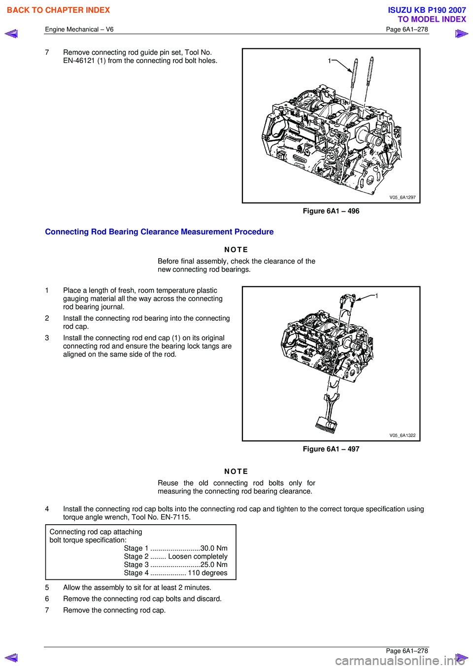
7 Remove connecting rod guide pin set, Tool No.
EN-46121 (1) from the connecting rod bolt holes.
Figure 6A1 – 496
Connecting Rod Bearing Clearance Measurement Procedure
NOTE
Before final assembly, check the clearance of the
new connecting rod bearings.
1 Place a length of fresh, room temperature plastic
gauging material all the way across the connecting
rod bearing journal.
2 Install the connecting rod bearing into the connecting
rod cap.
3 Install the connecting rod end cap (1) on its original
connecting rod and ensure t he bearing lock tangs are
aligned on the same side of the rod.
Figure 6A1 – 497
NOTE
Reuse the old connecting rod bolts only for
measuring the connecting rod bearing clearance.
4 Install the connecting rod cap bolts in to the connecting rod cap and tighten to the correct torque specification using
torque angle wrench, Tool No. EN-7115.
Connecting rod cap attaching
bolt torque specification:
Stage 1 .........................30.0 Nm
Stage 2 ........Loosen completely
Stage 3 .........................25.0 Nm
Stage 4 ..................110 degrees
5 Allow the assembly to sit for at least 2 minutes.
6 Remove the connecting rod cap bolts and discard.
7 Remove the connecting rod cap.
BACK TO CHAPTER INDEX
TO MODEL INDEX
ISUZU KB P190 2007
Page 3056 of 6020
Engine Mechanical – V6 Page 6A1–279
Page 6A1–279
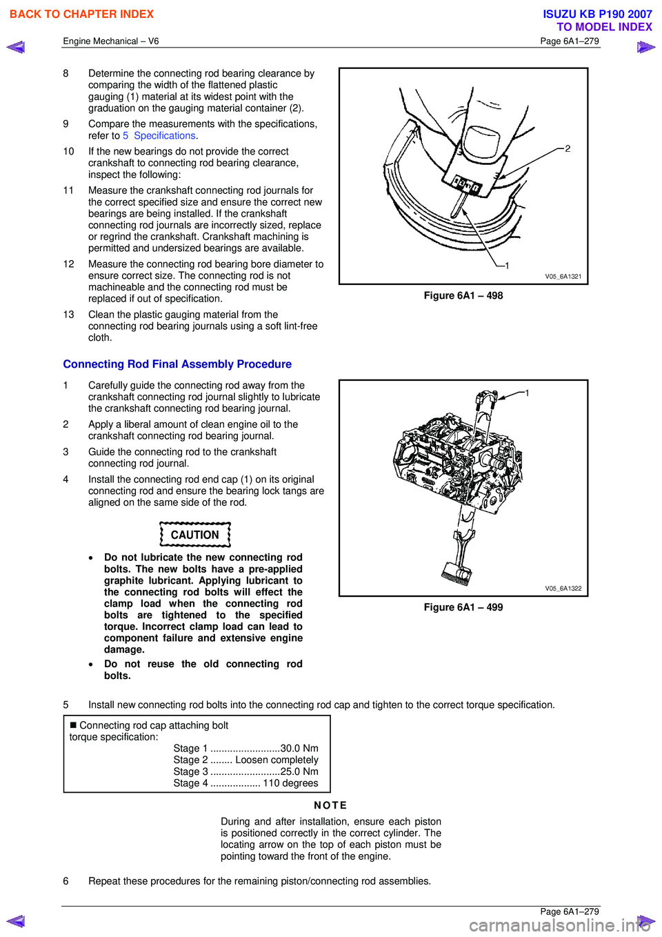
8 Determine the connecting rod bearing clearance by
comparing the width of the flattened plastic
gauging (1) material at its widest point with the
graduation on the gauging mate rial container (2).
9 Compare the measurements with the specifications,
refer to 5 Specifications .
10 If the new bearings do not provide the correct crankshaft to connecting rod bearing clearance,
inspect the following:
11 Measure the crankshaft connecting rod journals for the correct specified size and ensure the correct new
bearings are being installed. If the crankshaft
connecting rod journals are in correctly sized, replace
or regrind the crankshaft. Crankshaft machining is
permitted and undersized bearings are available.
12 Measure the connecting rod bearing bore diameter to
ensure correct size. The connecting rod is not
machineable and the connecting rod must be
replaced if out of specification.
13 Clean the plastic gauging material from the connecting rod bearing journals using a soft lint-free
cloth.
Figure 6A1 – 498
Connecting Rod Final Assembly Procedure
1 Carefully guide the connecting rod away from the crankshaft connecting rod journal slightly to lubricate
the crankshaft connecting rod bearing journal.
2 Apply a liberal amount of clean engine oil to the crankshaft connecting rod bearing journal.
3 Guide the connecting rod to the crankshaft connecting rod journal.
4 Install the connecting rod end cap (1) on its original
connecting rod and ensure t he bearing lock tangs are
aligned on the same side of the rod.
CAUTION
• Do not lubricate the new connecting rod
bolts. The new bolts have a pre-applied
graphite lubricant. Applying lubricant to
the connecting rod bolts will effect the
clamp load when the connecting rod
bolts are tightened to the specified
torque. Incorrect clamp load can lead to
component failure and extensive engine
damage.
• Do not reuse the old connecting rod
bolts.
Figure 6A1 – 499
5 Install new connecting rod bolts into the connecting r od cap and tighten to the correct torque specification.
�„ Connecting rod cap attaching bolt
torque specification:
Stage 1 .........................30.0 Nm
Stage 2 ........Loosen completely
Stage 3 .........................25.0 Nm
Stage 4 ..................110 degrees
NOTE
During and after installation, ensure each piston
is positioned correctly in the correct cylinder. The
locating arrow on the top of each piston must be
pointing toward the front of the engine.
6 Repeat these procedures for the rema ining piston/connecting rod assemblies.
BACK TO CHAPTER INDEX
TO MODEL INDEX
ISUZU KB P190 2007
Page 3065 of 6020
Engine Mechanical – V6 Page 6A1–288
Page 6A1–288
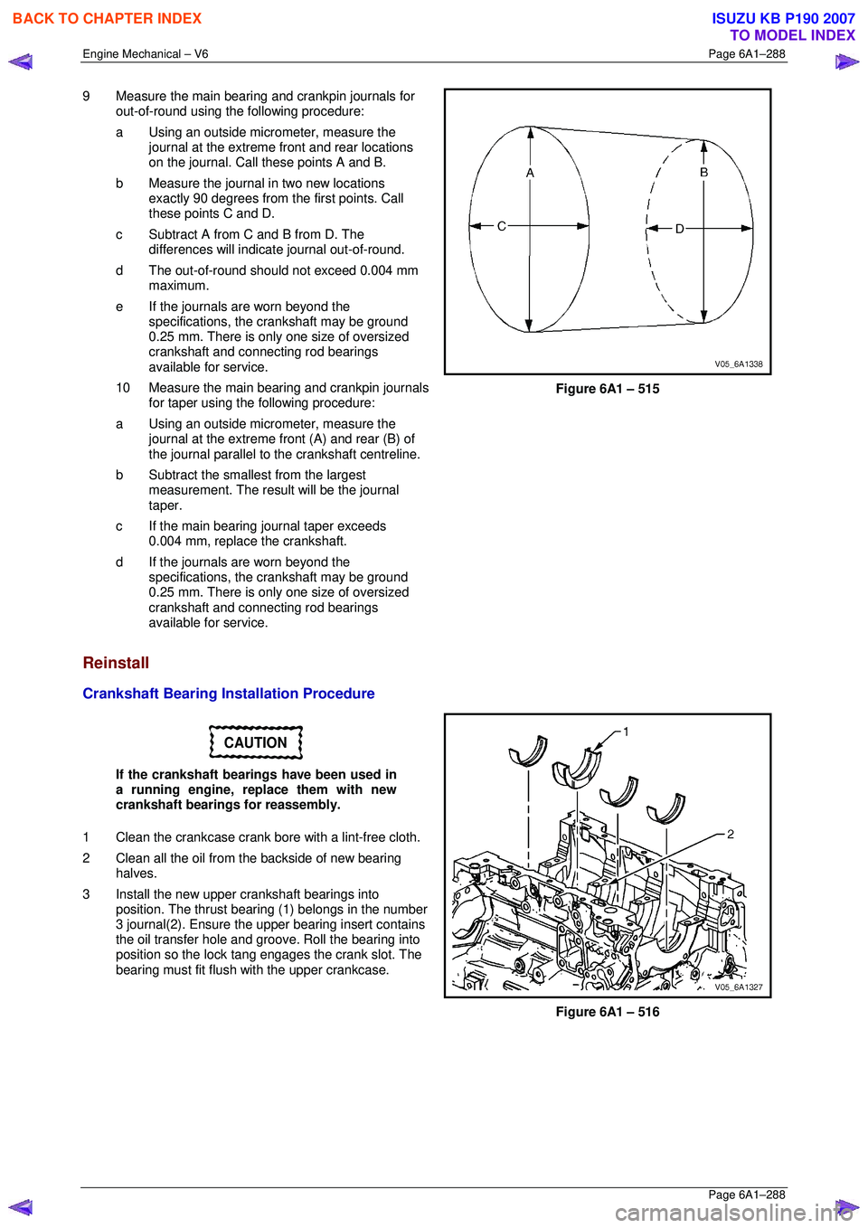
9 Measure the main bearing and crankpin journals for
out-of-round using the following procedure:
a Using an outside micr ometer, measure the
journal at the extreme front and rear locations
on the journal. Call these points A and B.
b Measure the journal in two new locations exactly 90 degrees from the first points. Call
these points C and D.
c Subtract A from C and B from D. The differences will indicate journal out-of-round.
d The out-of-round shoul d not exceed 0.004 mm
maximum.
e If the journals are worn beyond the specifications, the crankshaft may be ground
0.25 mm. There is only one size of oversized
crankshaft and connecting rod bearings
available for service.
10 Measure the main bearing and crankpin journals for taper using the following procedure:
a Using an outside micr ometer, measure the
journal at the extreme fr ont (A) and rear (B) of
the journal parallel to t he crankshaft centreline.
b Subtract the smallest from the largest measurement. The result will be the journal
taper.
c If the main bearing journal taper exceeds 0.004 mm, replace the crankshaft.
d If the journals are worn beyond the specifications, the crankshaft may be ground
0.25 mm. There is only one size of oversized
crankshaft and connecting rod bearings
available for service.
Figure 6A1 – 515
Reinstall
Crankshaft Bearing Installation Procedure
CAUTION
If the crankshaft bearings have been used in
a running engine, replace them with new
crankshaft bearings for reassembly.
1 Clean the crankcase crank bore with a lint-free cloth.
2 Clean all the oil from the backside of new bearing halves.
3 Install the new upper crankshaft bearings into position. The thrust beari ng (1) belongs in the number
3 journal(2). Ensure the upper bearing insert contains
the oil transfer hole and groove. Roll the bearing into
position so the lock tang engages the crank slot. The
bearing must fit flush with the upper crankcase.
Figure 6A1 – 516
BACK TO CHAPTER INDEX
TO MODEL INDEX
ISUZU KB P190 2007