Page 947 of 6020

ENGINE COOLING 6B – 3
MAIN DATA AND SPECIFICATIONS
Description Item M/T A/T
Cooling system
W ater pump type
Pump to crankshaft speed ratio (To 1)
Delivery volume lit (US/UK gal)/min
Pump speed at 3000 rpm
W ater temperature at 30 °C (86 °F)
Pump bearing type
Thermostat type
Valve initial opening temperature °C ( °F)
(Oil cooler thermo valve)
(EGR cooler thermo valve)
Valve full opening temperature °C ( °F)
(Oil cooler thermo valve)
(EGR cooler thermo valve)
Valve lift at fully open position mm (in)
(Oil cooler thermo valve)
(EGR cooler thermo valve) Engine coolant forced circulation
Centrifugal impeller type 1.2
100 (26.3/22.2)
Double row shaft
W ax pellet with jiggle valve 82 (180)
76.5 (170) 40 (104)
95 (203)
90 (194)
55 (131)
9.5 (0.37)
4.5 (0.18)
3.5 (0.14)
Radiator Tube type corrugated
Heat radiation capacity 93.0 kW (79,980 kcal/h)
Heat radiation area 11.63 m2 (1.081ft2)
Radiator front area 0.28m2 (0.026 ft2)
Radiator dry weight 52 N (5.3 kg/11.7 lb) 53 N (5.4 kg/11.9 lb)
Radiator cap valve opening pressure 93.3 ~ 122.7 kPa (13.5 ~ 17.8 psi)
Engine coolant capacity 2.4 lit (5.1 U.S pint) 2.3 lit (4.9 U.S pint)
Engine coolant total capacity 10.1 lit (21.3 U.S pint) 10.0 lit (21.1 U.S pint)
BACK TO CHAPTER INDEX
TO MODEL INDEX
ISUZU KB P190 2007
Page 982 of 6020
6C – 18 FUEL SYSTEM
INJECTION PUMP
REMOVAL AND INSTALLATION
Read this Section carefully before performing any removal and installation procedure. This Section gives you
important points as well as the order of operation. Be sure that you understand everything in this Section before you
begin.
Removal
1. Battery
Remove the battery from the battery tray.
Battery
Battery tray
P1010011
2. Drive Belt 1) Loosen the adjust bolt of the power steering pump pulley.
2) Remove the drive belt.
3. Power Steering Pump Assembly
P1010003
4. Accelerator Control Cable
Disconnect the accelerator cable from the intake throttle.
5. Vacuum Hose
Disconnect the vacuum hose from the EGR valve and the intake throttle.
6. Fan
BACK TO CHAPTER INDEX
TO MODEL INDEX
ISUZU KB P190 2007
Page 983 of 6020

FUEL SYSTEM 6C – 19
7. Power Steering Pump Bracket
6C-4 8. Throttle Position Sensor Harness Connector
(4JA1TC/4JH1TC only) Disconnect the harness connector from the throttle
position sensor.
9. Oil Level Gauge
10. Fuel Pipe 1) Disconnect the fuel hoses from the fuel filter or priming pump.
2) Disconnect the fuel hoses from the injection pump.
11. Fuel Filter Assembly (Except EURO III model)
6C-5
12. Fuel Filter Bracket (Except EURO III model)
13. Leak Off Hose
Disconnect the leak off hose at the injection pump.
14. Injection Pipe Clip
15. Injection Pipe
1) Loosen the injection pipe sleeve nuts at the delivery valve side and the injection nozzle side.
Note:
Do not apply excessive force to the injection pipes.
2) Loosen the injection pipe clip.
3) Remove the injection pipes.
Note:
Plug the delivery holder ports with the caps to prevent
the entry of foreign material.
16. Intake Manifold 1) Remove the EGR valve from the intake manifold and EGR pipe.
2) Loosen the intake rubber hoses clip.
3) Loosen the intake manifold bolts and nuts.
17. Injection Pump Cover (4JA1TC/4JH1TC only)
BACK TO CHAPTER INDEX
TO MODEL INDEX
ISUZU KB P190 2007
Page 986 of 6020

6C – 22 FUEL SYSTEM
4JA1T (L)
RTW 46CSH000101
4JA1TC/4JH1TC
RTW 36AMH000101
2. Injection Pump Bracket
1) Install the injection pump bracket (6) and the bracket bolts (7) and (8) to the cylinder body. Temporarily
tighten the bracket bolts.
2) Tighten the bracket bolts (7) to the specified torque.
3) Tighten the bracket bolts (8) to the specified torque.
Note:
Tighten the bracket bolt (8) first.
Injection Pump Bracket Torque N·m(kg·m / lb ft)
(8) 19 (1.9 / 14)
(7) 40 (4.1 / 30)
3. Timing Check Hole Cover
Install the timing check hole cover and tighten bolts to the
specified torque.
Timing Check Hole Cover Bolts
Torque N·m(kg·m / lb ft)
8 (0.8 / 69)
4. Injection Pump Cover (4JA1TC/4JH1TC only)
5. Intake Manifold
1) Install the intake manifold with gasket.
Intake Manifold Bolts
Torque N·m(kg·m / lb ft)
19 (1.9 / 14)
Intake Manifold Nuts Torque N·m(kg·m / lb ft)
24 (2.4 / 17)
2) Install the EGR valve to the intake manifold and EGR pipe temporarily.
3) Tighten the nuts and bolts to the specified torque
Torque N ⋅m (kg ⋅m/lb ft)
Nuts 24 (2.4/17)
Bolts 27 (2.8/20)
BACK TO CHAPTER INDEX
TO MODEL INDEX
ISUZU KB P190 2007
Page 988 of 6020
6C – 24 FUEL SYSTEM
13. Throttle Position Sensor Harness Connector
(4JA1TC/4JH1TC only)
Reconnect the harness connector to the throttle position
sensor.
14. Power Steering Pump Bracket
15. Fan
16. Vacuum Hose
Connect the vacuum hose to the EGR valve and the
intake throttle.
Euro under Euro I Euro II Euro III
4JA1L without with with Not used
4JA1TC Not used Not used Not used With cooler
(EGR cooler)
4JH1TC without with with With
(EGR cooler)
17. Accelerator Control Cable
1) Connect the accelerator cable to the injection pump (4JA1T) the intake throttle. (4JA1TC/4JH1TC only)
18. Power Steering Pump Assembly
19. Drive Belt
Install the drive belt and adjust the belt tension.
20. Battery
BACK TO CHAPTER INDEX
TO MODEL INDEX
ISUZU KB P190 2007
Page 1002 of 6020

SECTION 6D
ENGINE ELECTRICAL
TABLE OF CONTENTS
PAGE
Main Data and Specifications ......................................................................................... 6D - 2
General Description ........................................................................................................ 6D - 3
Torque Specifications ..................................................................................................... 6D - 5
Generator ...................................................................................................................... ... 6D - 7
Removal and Installation ............................................................................................ 6D - 7
Disassembly ................................................................................................................ 6D - 9
Inspection and Repair ................................................................................................. 6D - 12
Reassembly ................................................................................................................. 6D - 18
Starter Motor .................................................................................................................. .. 6D - 22
Removal and Installation ............................................................................................ 6D - 22
Disassembly ................................................................................................................ 6D - 23
Inspection and Repair ................................................................................................. 6D - 26
Reassembly ................................................................................................................. 6D - 29
Pre-heating System ......................................................................................................... 6D -33
Inspection and Repair ................................................................................................. 6D -33
Glow Relay ................................................................................................................... 6D -33
Glow Plug..................................................................................................................... 6D -33
EGR System ................................................................................................................. 6D -33
ENGINE ELECTRICAL 6D – 1
BACK TO CHAPTER INDEX
TO MODEL INDEX
ISUZU KB P190 2007
Page 1004 of 6020
ENGINE ELECTRICAL 6D – 3
GENERAL DESCRIPTION
GENERATOR STARTER MOTOR
066L300004 065L300002
The basic charging system is the IC integral regulator charging system. The internal components are connected
electrically as shown in charging circuit diagram.
The generator features a solid state regulator that is mounted inside the generator. All regulator components are
enclosed into a solid mold, and this unit along with the brush holder assembly is attached to the slip ring end frame.
The generator voltage setting cannot be adjusted.
The starter motor circuit is composed of a 4-pole 4-brush type direct current series motor. The starter motor circuit
utilizes negative ground polarity.
BACK TO CHAPTER INDEX
TO MODEL INDEX
ISUZU KB P190 2007
Page 1027 of 6020

6D – 26 ENGINE ELECTRICAL
INSPECTION AND REPAIR
Make the necessary adjustments, repairs, and part replacement if excessive wear or damage is discovered during
inspection.
ARMATURE
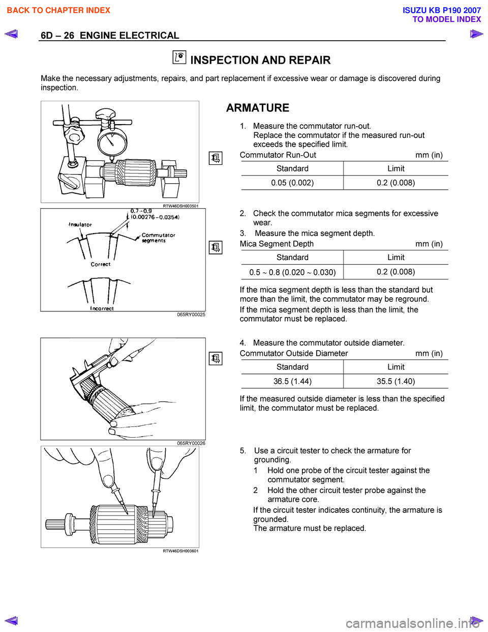
1. Measure the commutator run-out. Replace the commutator if the measured run-out
exceeds the specified limit.
Commutator Run-Out mm (in)
Standard Limit
0.05 (0.002) 0.2 (0.008)
RTW46DSH003501
2. Check the commutator mica segments for excessive
wear.
3. Measure the mica segment depth.
Mica Segment Depth mm (in)
Standard Limit
0.5 ∼ 0.8 (0.020 ∼ 0.030) 0.2 (0.008)
065RY00025
If the mica segment depth is less than the standard but
more than the limit, the commutator may be reground.
If the mica segment depth is less than the limit, the
commutator must be replaced.
4. Measure the commutator outside diameter.
Commutator Outside Diameter mm (in)
Standard Limit
36.5 (1.44) 35.5 (1.40)
If the measured outside diameter is less than the specified
limit, the commutator must be replaced.
065RY00026
RTW46DSH003601
5. Use a circuit tester to check the armature for
grounding.
1 Hold one probe of the circuit tester against the commutator segment.
2 Hold the other circuit tester probe against the armature core.
If the circuit tester indicates continuity, the armature is grounded.
The armature must be replaced.
BACK TO CHAPTER INDEX
TO MODEL INDEX
ISUZU KB P190 2007