2007 ISUZU KB P190 EGR
[x] Cancel search: EGRPage 1186 of 6020
6E-152 Engine Control System (4JH1)
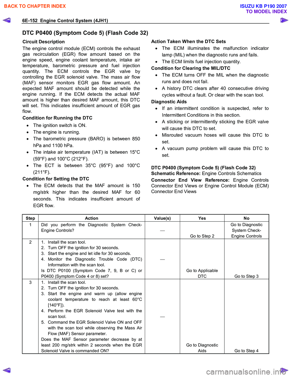
DTC P0400 (Symptom Code 5) (Flash Code 32)
Circuit Description
The engine control module (ECM) controls the exhaust
gas recirculation (EGR) flow amount based on the
engine speed, engine coolant temperature, intake ai
r
temperature, barometric pressure and fuel injection
quantity. The ECM controls the EGR valve b
y
controlling the EGR solenoid valve. The mass air flo
w
(MAF) sensor monitors EGR gas flow amount. An
expected MAF amount should be detected while the
engine running. If the ECM detects the actual MAF
amount is higher than desired MAF amount, this DTC
will set. This indicates insufficient amount of EGR gas
flow.
Condition for Running the DTC
• The ignition switch is ON.
• The engine is running.
• The barometric pressure (BARO) is between 850
hPa and 1100 hPa.
• The intake air temperature (IAT) is between 15°C
(59°F) and 100°C (212°F).
• The ECT is between 35°C (95°F) and 100°C
(211°F).
Condition for Setting the DTC
• The ECM detects that the MAF amount is 150
mg/strk higher than the desired MAF for 60
seconds. This indicates insufficient amount o
f
EGR flow.
Action Taken When the DTC Sets
• The ECM illuminates the malfunction indicato
r
lamp (MIL) when the diagnostic runs and fails.
• The ECM limits fuel injection quantity.
Condition for Clearing the MIL/DTC
• The ECM turns OFF the MIL when the diagnostic
runs and does not fail.
• A history DTC clears after 40 consecutive driving
cycles without a fault. Or clear with the scan tool.
Diagnostic Aids
• If an intermittent condition is suspected, refer to
Intermittent Conditions in this section.
• A sticking or intermittently sticking the EGR valve
will cause this DTC to set.
• Misrouted vacuum hoses will cause this DTC to
set.
•
A vacuum pump problem will cause this DTC to
set.
DTC P0400 (Symptom Code 5) (Flash Code 32)
Schematic Reference: Engine Controls Schematics
Connector End View Reference: Engine Controls
Connector End Views or Engine Control Module (ECM)
Connector End Views
Step Action Value(s) Yes No
1 Did you perform the Diagnostic System Check-
Engine Controls?
Go to Step 2 Go to Diagnostic
System Check-
Engine Controls
2 1. Install the scan tool. 2. Turn OFF the ignition for 30 seconds.
3. Start the engine and let idle for 30 seconds.
4. Monitor the Diagnostic Trouble Code (DTC) Information with the scan tool.
Is DTC P0100 (Symptom Code 7, 9, B or C) or
P0400 (Symptom Code 4 or 8) set?
Go to Applicable DTC Go to Step 3
3 1. Install the scan tool. 2. Turn OFF the ignition for 30 seconds.
3. Start the engine and warm up (allow engine coolant temperature to reach at least 60°C
[140°F]).
4. Perform the EGR Solenoid Valve test with the scan tool.
5. Command the EGR Solenoid Valve ON and OFF with the scan tool while observing the Mass Air
Flow (MAF) Sensor parameter.
Does the MAF Sensor parameter decrease by at
least 200 mg/strk within 2 seconds when the EGR
Solenoid Valve is commanded ON?
Go to Diagnostic Aids Go to Step 4
BACK TO CHAPTER INDEX
TO MODEL INDEX
ISUZU KB P190 2007
Page 1187 of 6020
Engine Control System (4JH1) 6E-153
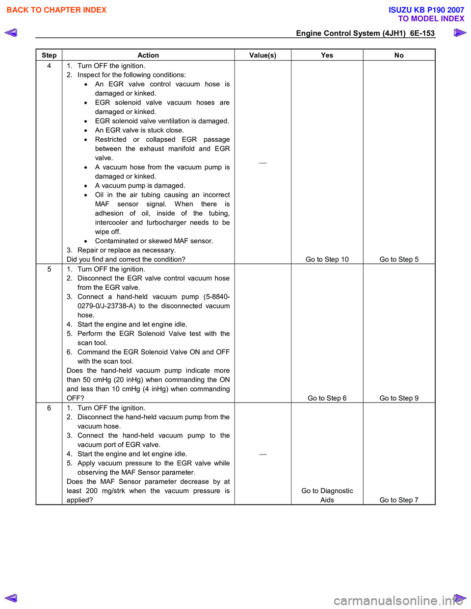
Step Action Value(s) Yes No
4 1. Turn OFF the ignition.
2. Inspect for the following conditions: • An EGR valve control vacuum hose is
damaged or kinked.
• EGR solenoid valve vacuum hoses are
damaged or kinked.
• EGR solenoid valve ventilation is damaged.
• An EGR valve is stuck close.
• Restricted or collapsed EGR passage
between the exhaust manifold and EGR
valve.
• A vacuum hose from the vacuum pump is
damaged or kinked.
• A vacuum pump is damaged.
• Oil in the air tubing causing an incorrect
MAF sensor signal. W hen there is
adhesion of oil, inside of the tubing,
intercooler and turbocharger needs to be
wipe off.
• Contaminated or skewed MAF sensor.
3. Repair or replace as necessary.
Did you find and correct the condition?
Go to Step 10 Go to Step 5
5 1. Turn OFF the ignition. 2. Disconnect the EGR valve control vacuum hose from the EGR valve.
3. Connect a hand-held vacuum pump (5-8840- 0279-0/J-23738-A) to the disconnected vacuum
hose.
4. Start the engine and let engine idle.
5. Perform the EGR Solenoid Valve test with the scan tool.
6. Command the EGR Solenoid Valve ON and OFF with the scan tool.
Does the hand-held vacuum pump indicate more
than 50 cmHg (20 inHg) when commanding the ON
and less than 10 cmHg (4 inHg) when commanding
OFF?
Go to Step 6 Go to Step 9
6 1. Turn OFF the ignition. 2. Disconnect the hand-held vacuum pump from the vacuum hose.
3. Connect the hand-held vacuum pump to the vacuum port of EGR valve.
4. Start the engine and let engine idle.
5. Apply vacuum pressure to the EGR valve while observing the MAF Sensor parameter.
Does the MAF Sensor parameter decrease by at
least 200 mg/strk when the vacuum pressure is
applied?
Go to Diagnostic Aids Go to Step 7
BACK TO CHAPTER INDEX
TO MODEL INDEX
ISUZU KB P190 2007
Page 1188 of 6020
6E-154 Engine Control System (4JH1)
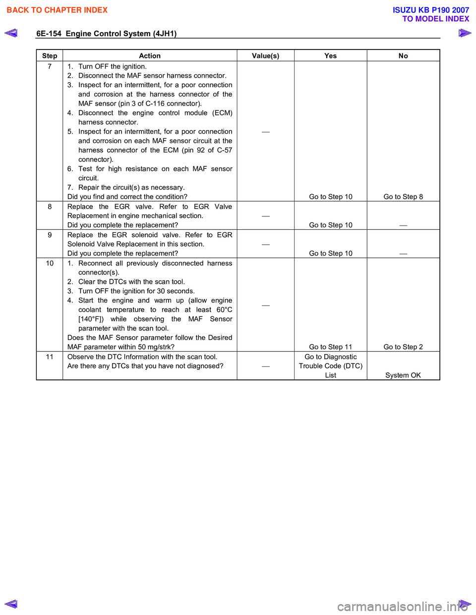
Step Action Value(s) Yes No
7 1. Turn OFF the ignition.
2. Disconnect the MAF sensor harness connector.
3. Inspect for an intermittent, for a poor connection and corrosion at the harness connector of the
MAF sensor (pin 3 of C-116 connector).
4. Disconnect the engine control module (ECM) harness connector.
5. Inspect for an intermittent, for a poor connection and corrosion on each MAF sensor circuit at the
harness connector of the ECM (pin 92 of C-57
connector).
6. Test for high resistance on each MAF sensor circuit.
7. Repair the circuit(s) as necessary.
Did you find and correct the condition?
Go to Step 10 Go to Step 8
8 Replace the EGR valve. Refer to EGR Valve Replacement in engine mechanical section.
Did you complete the replacement?
Go to Step 10
9 Replace the EGR solenoid valve. Refer to EGR
Solenoid Valve Replacement in this section.
Did you complete the replacement?
Go to Step 10
10 1. Reconnect all previously disconnected harness
connector(s).
2. Clear the DTCs with the scan tool.
3. Turn OFF the ignition for 30 seconds.
4. Start the engine and warm up (allow engine coolant temperature to reach at least 60°C
[140°F]) while observing the MAF Sensor
parameter with the scan tool.
Does the MAF Sensor parameter follow the Desired
MAF parameter within 50 mg/strk?
Go to Step 11 Go to Step 2
11 Observe the DTC Information with the scan tool. Are there any DTCs that you have not diagnosed? Go to Diagnostic
Trouble Code (DTC) List System OK
BACK TO CHAPTER INDEX
TO MODEL INDEX
ISUZU KB P190 2007
Page 1189 of 6020
Engine Control System (4JH1) 6E-155
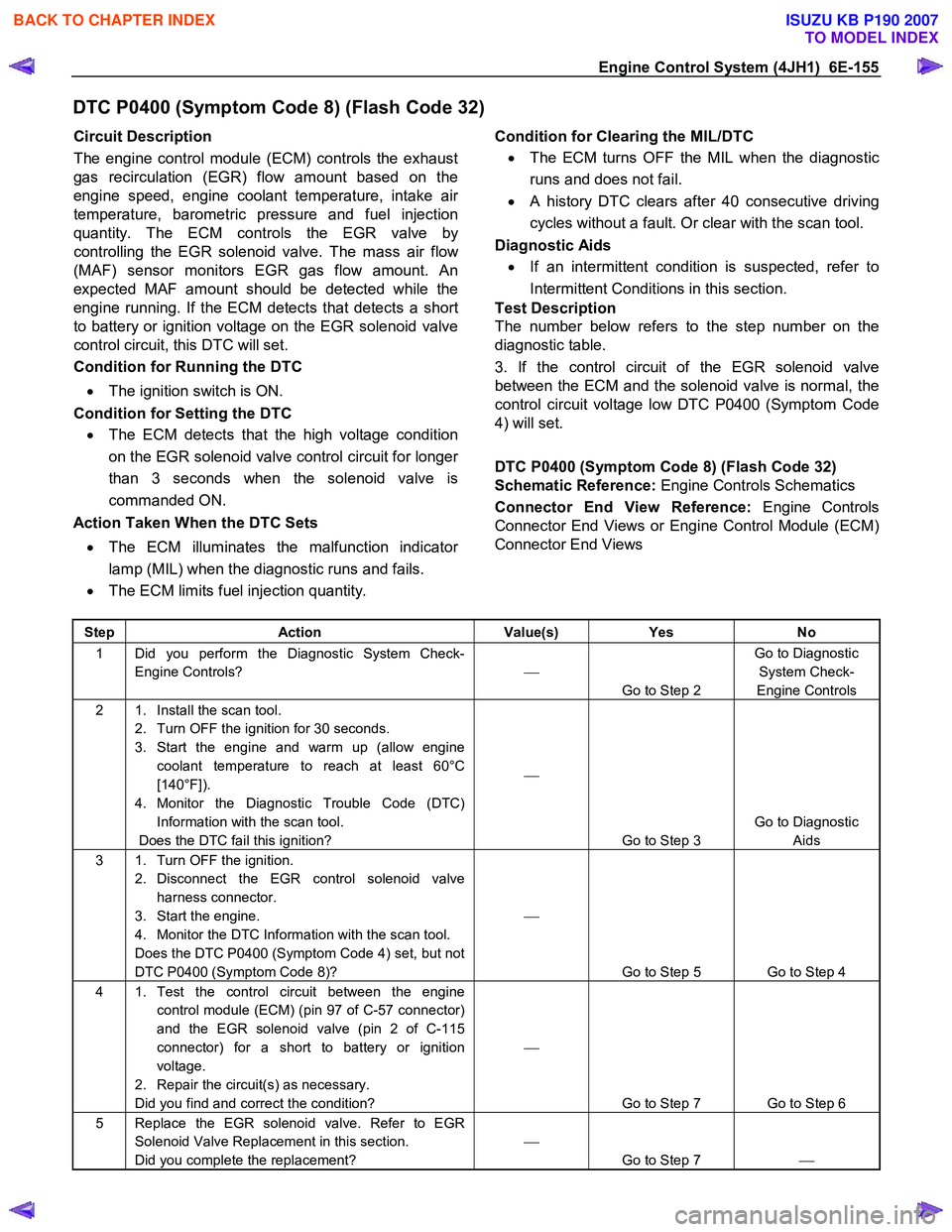
DTC P0400 (Symptom Code 8) (Flash Code 32)
Circuit Description
The engine control module (ECM) controls the exhaust
gas recirculation (EGR) flow amount based on the
engine speed, engine coolant temperature, intake ai
r
temperature, barometric pressure and fuel injection
quantity. The ECM controls the EGR valve by
controlling the EGR solenoid valve. The mass air flo
w
(MAF) sensor monitors EGR gas flow amount. An
expected MAF amount should be detected while the
engine running. If the ECM detects that detects a short
to battery or ignition voltage on the EGR solenoid valve
control circuit, this DTC will set.
Condition for Running the DTC
• The ignition switch is ON.
Condition for Setting the DTC • The ECM detects that the high voltage condition
on the EGR solenoid valve control circuit for longe
r
than 3 seconds when the solenoid valve is
commanded ON.
Action Taken When the DTC Sets
• The ECM illuminates the malfunction indicato
r
lamp (MIL) when the diagnostic runs and fails.
• The ECM limits fuel injection quantity.
Condition for Clearing the MIL/DTC
• The ECM turns OFF the MIL when the diagnostic
runs and does not fail.
• A history DTC clears after 40 consecutive driving
cycles without a fault. Or clear with the scan tool.
Diagnostic Aids
• If an intermittent condition is suspected, refer to
Intermittent Conditions in this section.
Test Description
The number below refers to the step number on the
diagnostic table.
3. If the control circuit of the EGR solenoid valve
between the ECM and the solenoid valve is normal, the
control circuit voltage low DTC P0400 (Symptom Code
4) will set.
DTC P0400 (Symptom Code 8) (Flash Code 32)
Schematic Reference: Engine Controls Schematics
Connector End View Reference: Engine Controls
Connector End Views or Engine Control Module (ECM)
Connector End Views
Step Action Value(s) Yes No
1 Did you perform the Diagnostic System Check-
Engine Controls?
Go to Step 2 Go to Diagnostic
System Check-
Engine Controls
2 1. Install the scan tool. 2. Turn OFF the ignition for 30 seconds.
3. Start the engine and warm up (allow engine coolant temperature to reach at least 60°C
[140°F]).
4. Monitor the Diagnostic Trouble Code (DTC) Information with the scan tool.
Does the DTC fail this ignition?
Go to Step 3 Go to Diagnostic
Aids
3 1. Turn OFF the ignition. 2. Disconnect the EGR control solenoid valve harness connector.
3. Start the engine.
4. Monitor the DTC Information with the scan tool.
Does the DTC P0400 (Symptom Code 4) set, but not
DTC P0400 (Symptom Code 8)?
Go to Step 5 Go to Step 4
4 1. Test the control circuit between the engine control module (ECM) (pin 97 of C-57 connector)
and the EGR solenoid valve (pin 2 of C-115
connector) for a short to battery or ignition
voltage.
2. Repair the circuit(s) as necessary.
Did you find and correct the condition?
Go to Step 7 Go to Step 6
5 Replace the EGR solenoid valve. Refer to EGR Solenoid Valve Replacement in this section.
Did you complete the replacement?
Go to Step 7
BACK TO CHAPTER INDEX
TO MODEL INDEX
ISUZU KB P190 2007
Page 1209 of 6020
Engine Control System (4JH1) 6E-175
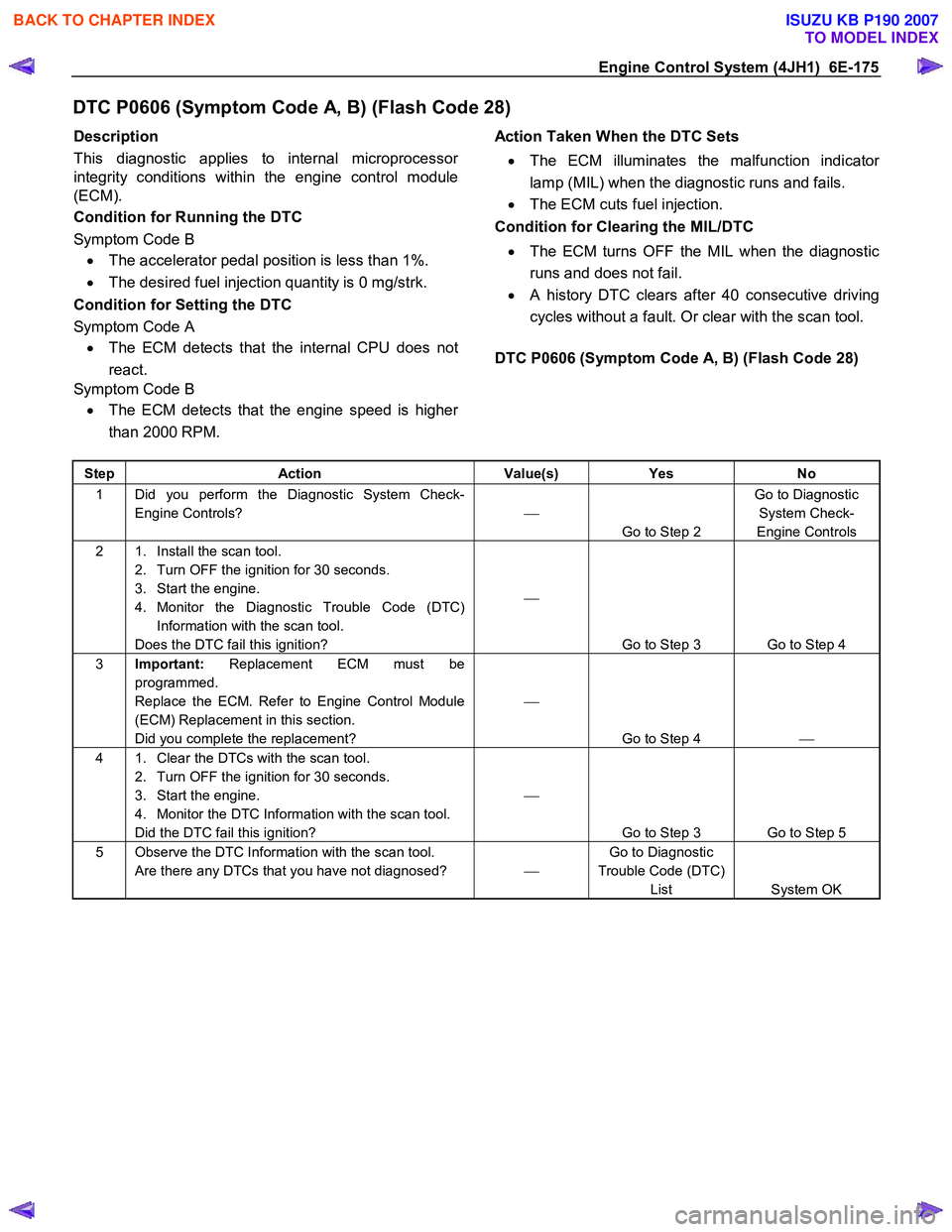
DTC P0606 (Symptom Code A, B) (Flash Code 28)
Description
This diagnostic applies to internal microprocesso
r
integrity conditions within the engine control module
(ECM).
Condition for Running the DTC
Symptom Code B • The accelerator pedal position is less than 1%.
• The desired fuel injection quantity is 0 mg/strk.
Condition for Setting the DTC
Symptom Code A • The ECM detects that the internal CPU does not
react.
Symptom Code B
• The ECM detects that the engine speed is highe
r
than 2000 RPM.
Action Taken When the DTC Sets
• The ECM illuminates the malfunction indicato
r
lamp (MIL) when the diagnostic runs and fails.
• The ECM cuts fuel injection.
Condition for Clearing the MIL/DTC
• The ECM turns OFF the MIL when the diagnostic
runs and does not fail.
• A history DTC clears after 40 consecutive driving
cycles without a fault. Or clear with the scan tool.
DTC P0606 (Symptom Code A, B) (Flash Code 28)
Step Action Value(s) Yes No
1 Did you perform the Diagnostic System Check-
Engine Controls?
Go to Step 2 Go to Diagnostic
System Check-
Engine Controls
2 1. Install the scan tool. 2. Turn OFF the ignition for 30 seconds.
3. Start the engine.
4. Monitor the Diagnostic Trouble Code (DTC) Information with the scan tool.
Does the DTC fail this ignition?
Go to Step 3 Go to Step 4
3 Important: Replacement ECM must be
programmed.
Replace the ECM. Refer to Engine Control Module
(ECM) Replacement in this section.
Did you complete the replacement?
Go to Step 4
4 1. Clear the DTCs with the scan tool.
2. Turn OFF the ignition for 30 seconds.
3. Start the engine.
4. Monitor the DTC Information with the scan tool.
Did the DTC fail this ignition?
Go to Step 3 Go to Step 5
5 Observe the DTC Information with the scan tool. Are there any DTCs that you have not diagnosed? Go to Diagnostic
Trouble Code (DTC) List System OK
BACK TO CHAPTER INDEX
TO MODEL INDEX
ISUZU KB P190 2007
Page 1250 of 6020
6E-216 Engine Control System (4JH1)
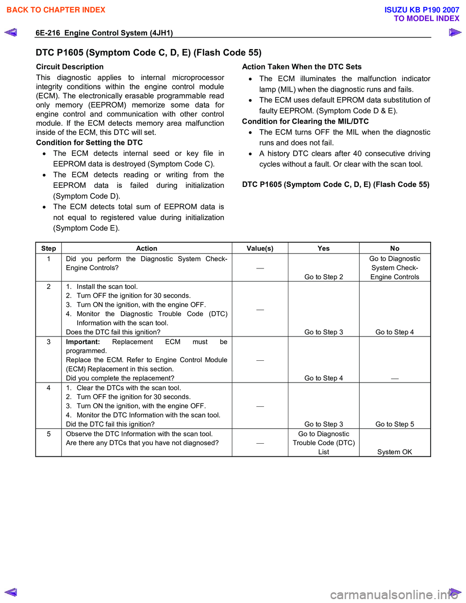
DTC P1605 (Symptom Code C, D, E) (Flash Code 55)
Circuit Description
This diagnostic applies to internal microprocesso
r
integrity conditions within the engine control module
(ECM). The electronically erasable programmable read
only memory (EEPROM) memorize some data fo
r
engine control and communication with other control
module. If the ECM detects memory area malfunction
inside of the ECM, this DTC will set.
Condition for Setting the DTC
• The ECM detects internal seed or key file in
EEPROM data is destroyed (Symptom Code C).
• The ECM detects reading or writing from the
EEPROM data is failed during initialization
(Symptom Code D).
• The ECM detects total sum of EEPROM data is
not equal to registered value during initialization
(Symptom Code E).
Action Taken When the DTC Sets
• The ECM illuminates the malfunction indicato
r
lamp (MIL) when the diagnostic runs and fails.
• The ECM uses default EPROM data substitution o
f
faulty EEPROM. (Symptom Code D & E).
Condition for Clearing the MIL/DTC • The ECM turns OFF the MIL when the diagnostic
runs and does not fail.
• A history DTC clears after 40 consecutive driving
cycles without a fault. Or clear with the scan tool.
DTC P1605 (Symptom Code C, D, E) (Flash Code 55)
Step Action Value(s) Yes No
1 Did you perform the Diagnostic System Check-
Engine Controls?
Go to Step 2 Go to Diagnostic
System Check-
Engine Controls
2 1. Install the scan tool. 2. Turn OFF the ignition for 30 seconds.
3. Turn ON the ignition, with the engine OFF.
4. Monitor the Diagnostic Trouble Code (DTC) Information with the scan tool.
Does the DTC fail this ignition?
Go to Step 3 Go to Step 4
3 Important: Replacement ECM must be
programmed.
Replace the ECM. Refer to Engine Control Module
(ECM) Replacement in this section.
Did you complete the replacement?
Go to Step 4
4 1. Clear the DTCs with the scan tool.
2. Turn OFF the ignition for 30 seconds.
3. Turn ON the ignition, with the engine OFF.
4. Monitor the DTC Information with the scan tool.
Did the DTC fail this ignition?
Go to Step 3 Go to Step 5
5 Observe the DTC Information with the scan tool. Are there any DTCs that you have not diagnosed? Go to Diagnostic
Trouble Code (DTC) List System OK
BACK TO CHAPTER INDEX
TO MODEL INDEX
ISUZU KB P190 2007
Page 1294 of 6020
6E-260 Engine Control System (4JH1)
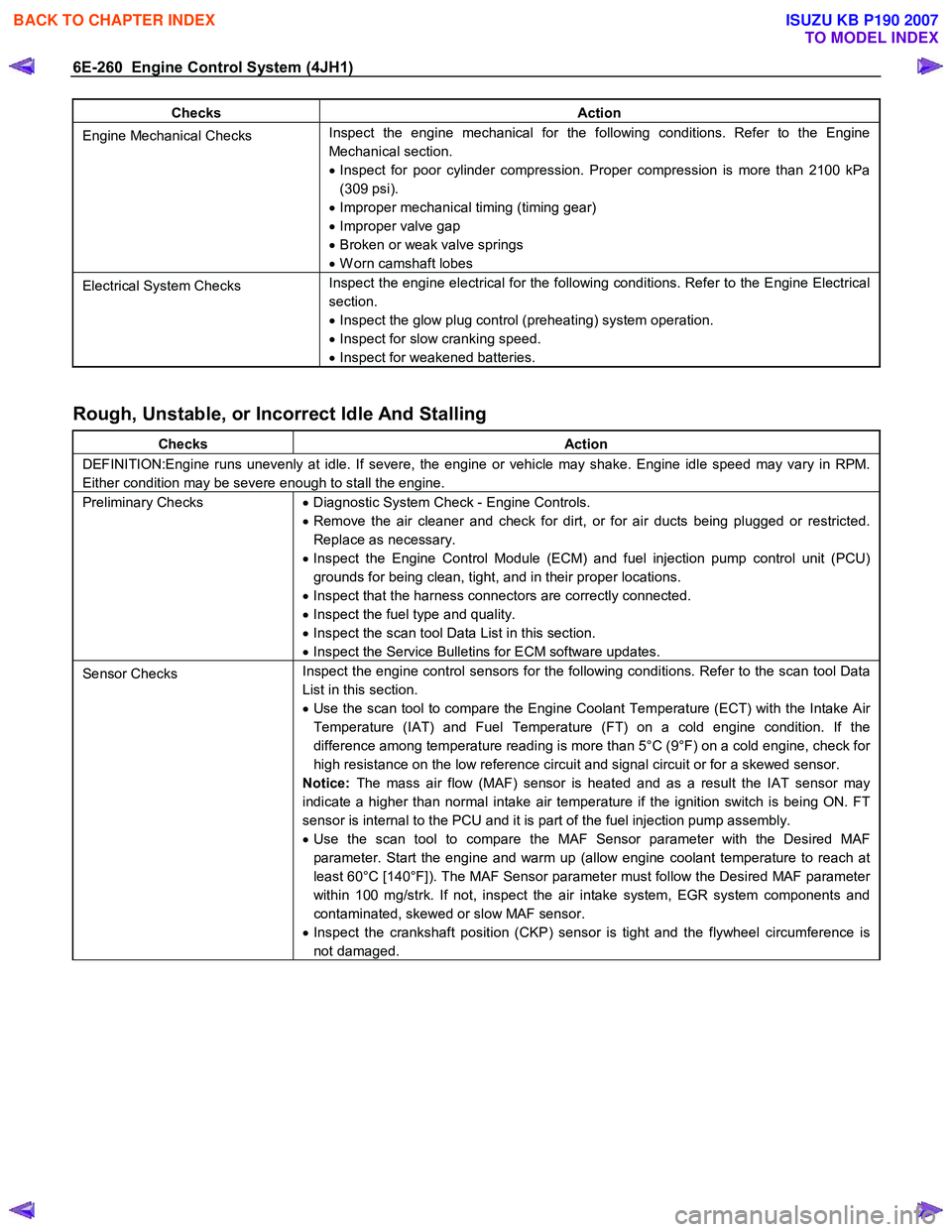
Checks Action
Engine Mechanical Checks Inspect the engine mechanical for the following conditions. Refer to the Engine
Mechanical section.
• Inspect for poor cylinder compression. Proper compression is more than 2100 kPa
(309 psi).
• Improper mechanical timing (timing gear)
• Improper valve gap
• Broken or weak valve springs
• W orn camshaft lobes
Electrical System Checks Inspect the engine electrical for the following conditions. Refer to the Engine Electrical
section.
• Inspect the glow plug control (preheating) system operation.
• Inspect for slow cranking speed.
• Inspect for weakened batteries.
Rough, Unstable, or Incorrect Idle And Stalling
Checks Action
DEFINITION:Engine runs unevenly at idle. If severe, the engine or vehicle may shake. Engine idle speed may vary in RPM.
Either condition may be severe enough to stall the engine.
Preliminary Checks • Diagnostic System Check - Engine Controls.
• Remove the air cleaner and check for dirt, or for air ducts being plugged or restricted.
Replace as necessary.
• Inspect the Engine Control Module (ECM) and fuel injection pump control unit (PCU)
grounds for being clean, tight, and in their proper locations.
• Inspect that the harness connectors are correctly connected.
• Inspect the fuel type and quality.
• Inspect the scan tool Data List in this section.
• Inspect the Service Bulletins for ECM software updates.
Sensor Checks Inspect the engine control sensors for the following conditions. Refer to the scan tool Data
List in this section.
• Use the scan tool to compare the Engine Coolant Temperature (ECT) with the Intake Air
Temperature (IAT) and Fuel Temperature (FT) on a cold engine condition. If the
difference among temperature reading is more than 5°C (9°F) on a cold engine, check for
high resistance on the low reference circuit and signal circuit or for a skewed sensor.
Notice: The mass air flow (MAF) sensor is heated and as a result the IAT sensor may
indicate a higher than normal intake air temperature if the ignition switch is being ON. FT
sensor is internal to the PCU and it is part of the fuel injection pump assembly.
• Use the scan tool to compare the MAF Sensor parameter with the Desired MAF
parameter. Start the engine and warm up (allow engine coolant temperature to reach at
least 60°C [140°F]). The MAF Sensor parameter must follow the Desired MAF parameter
within 100 mg/strk. If not, inspect the air intake system, EGR system components and
contaminated, skewed or slow MAF sensor.
• Inspect the crankshaft position (CKP) sensor is tight and the flywheel circumference is
not damaged.
BACK TO CHAPTER INDEX
TO MODEL INDEX
ISUZU KB P190 2007
Page 1296 of 6020
6E-262 Engine Control System (4JH1)
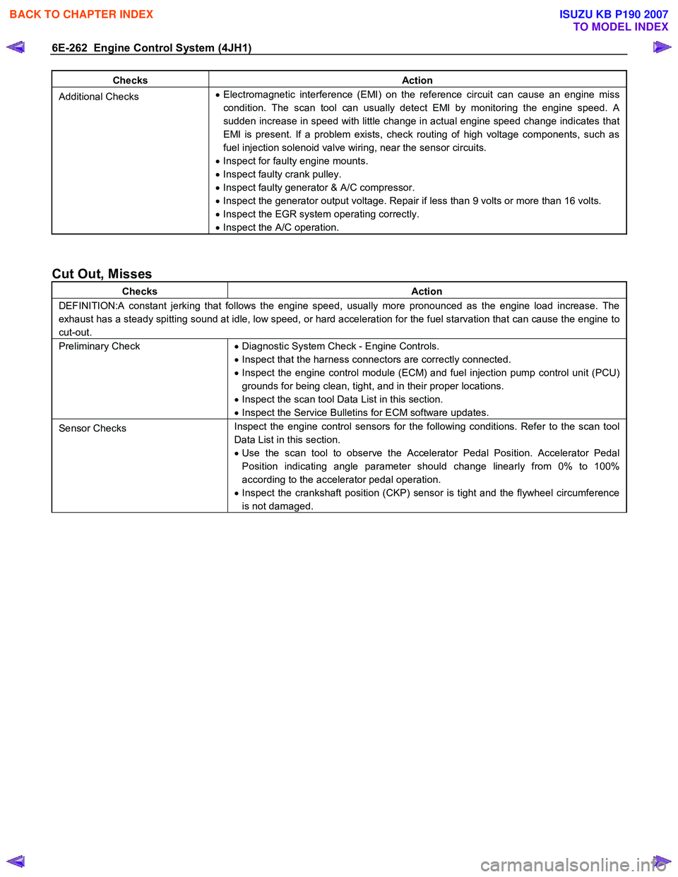
Checks Action
Additional Checks •
Electromagnetic interference (EMI) on the reference circuit can cause an engine miss
condition. The scan tool can usually detect EMI by monitoring the engine speed. A
sudden increase in speed with little change in actual engine speed change indicates that
EMI is present. If a problem exists, check routing of high voltage components, such as
fuel injection solenoid valve wiring, near the sensor circuits.
• Inspect for faulty engine mounts.
• Inspect faulty crank pulley.
• Inspect faulty generator & A/C compressor.
• Inspect the generator output voltage. Repair if less than 9 volts or more than 16 volts.
• Inspect the EGR system operating correctly.
• Inspect the A/C operation.
Cut Out, Misses
Checks Action
DEFINITION:A constant jerking that follows the engine speed, usually more pronounced as the engine load increase. The
exhaust has a steady spitting sound at idle, low speed, or hard acceleration for the fuel starvation that can cause the engine to
cut-out.
Preliminary Check • Diagnostic System Check - Engine Controls.
• Inspect that the harness connectors are correctly connected.
• Inspect the engine control module (ECM) and fuel injection pump control unit (PCU)
grounds for being clean, tight, and in their proper locations.
• Inspect the scan tool Data List in this section.
• Inspect the Service Bulletins for ECM software updates.
Sensor Checks Inspect the engine control sensors for the following conditions. Refer to the scan tool
Data List in this section.
• Use the scan tool to observe the Accelerator Pedal Position. Accelerator Pedal
Position indicating angle parameter should change linearly from 0% to 100%
according to the accelerator pedal operation.
• Inspect the crankshaft position (CKP) sensor is tight and the flywheel circumference
is not damaged.
BACK TO CHAPTER INDEX
TO MODEL INDEX
ISUZU KB P190 2007