Page 1369 of 6020

ENGINE MECHANICAL (4JK1/4JJ1) 6A-9
Excessive black exhaust smoke
Condition Possible Cause Correction
Bad injection timing Engine control system malfunction System diagnosis
Carbon deposit at nozzle tip Clean fuel injector assembly
Sticking nozzle Replace fuel injector assembly
Bad fuel injector condition
Engine control system malfunction System diagnosis
Excessive valve clearance Adjust clearance
Sticking valve stem (valve open) Repair or replace valve
Damaged valve spring Replace spring
Valve seat abrasion Repair valve seat
Compression leakage due to
damaged piston ring Replace piston ring
Damaged gasket
Replace gasket
Insufficient compression pressure
Piston scoring Replace piston
W ater in fuel Drain existing fuel and replace with
new fuel Fuel condition
Poor fuel quality Drain existing fuel and replace with
new fuel
Clogged intake pipes Clean or replace pipes Poor engine aspiration
Clogged air cleaner element Clean or replace element
Defective sensor Replace sensor Malfunction detected by engine
control system Engine control system malfunction System diagnosis
Intake throttle valve sticking Repair or replace valve
EGR valve sticking Repair or replace valve
EGR valve and/or intake throttle
valve malfunction
Engine control system malfunction System diagnosis
Damaged turbocharger blade Replace turbocharger
Rough turbocharger shaft rotation Replace turbocharger
Oil leakage from oil seal Replace turbocharger
Turbocharger malfunction
Broken actuator Replace turbocharger
BACK TO CHAPTER INDEX
TO MODEL INDEX
ISUZU KB P190 2007
Page 1387 of 6020
ENGINE MECHANICAL (4JK1/4JJ1) 6A-27
Intake Manifold
Components (Standard Output)
RTW 76ALF000201
Legend 1. Intake Duct
2. Throttle Assembly
3. Intake Manifold Gasket 4. Intake Manifold
5. EGR Valve Assembly Gasket
6. EGR Valve Assembly
BACK TO CHAPTER INDEX
TO MODEL INDEX
ISUZU KB P190 2007
Page 1388 of 6020
6A-28 ENGINE MECHANICAL (4JK1/4JJ1)
Components (High Output)
RTW 76ALF000301
Legend 1. Intake Duct
2. Intake Throttle
3. Intake Throttle Gasket
4. Intake Manifold Gasket 5. Intake Manifold
6. EGR Valve Assembly Gasket
7. EGR Valve Assembly
8. Bracket
BACK TO CHAPTER INDEX
TO MODEL INDEX
ISUZU KB P190 2007
Page 1389 of 6020
ENGINE MECHANICAL (4JK1/4JJ1) 6A-29
Removal
1. Remove the engine cover.
2. Disconnect the connectors. • Fuel Injector
• Throttle Assembly
• EGR Valve
• Glow Plug
• Barometric Sensor
• A/C Compressor Connector
3. Remove the A/C belt
4. Remove the A/C compressor.
5. Remove the A/C compressor bracket.
6. Remove the intake air duct (Standard output).
RTW 56ASH024801
Legend
1. A/C Compressor Bracket
2. Intake Air Duct
3. A/C Compressor
7. Remove the intercooler (High output).
• Disconnect the BARO sensor harness
connector (2).
• Remove the two intake hoses.
• Remove the intercooler (1).
RTW 76ASH000501
8. Remove the injector leak-off hose (1).
RTW 56ASH024301
9. Remove the engine oil level gauge guide tube.
10. Remove the EGR valve.
BACK TO CHAPTER INDEX
TO MODEL INDEX
ISUZU KB P190 2007
Page 1391 of 6020

ENGINE MECHANICAL (4JK1/4JJ1) 6A-31
Installation
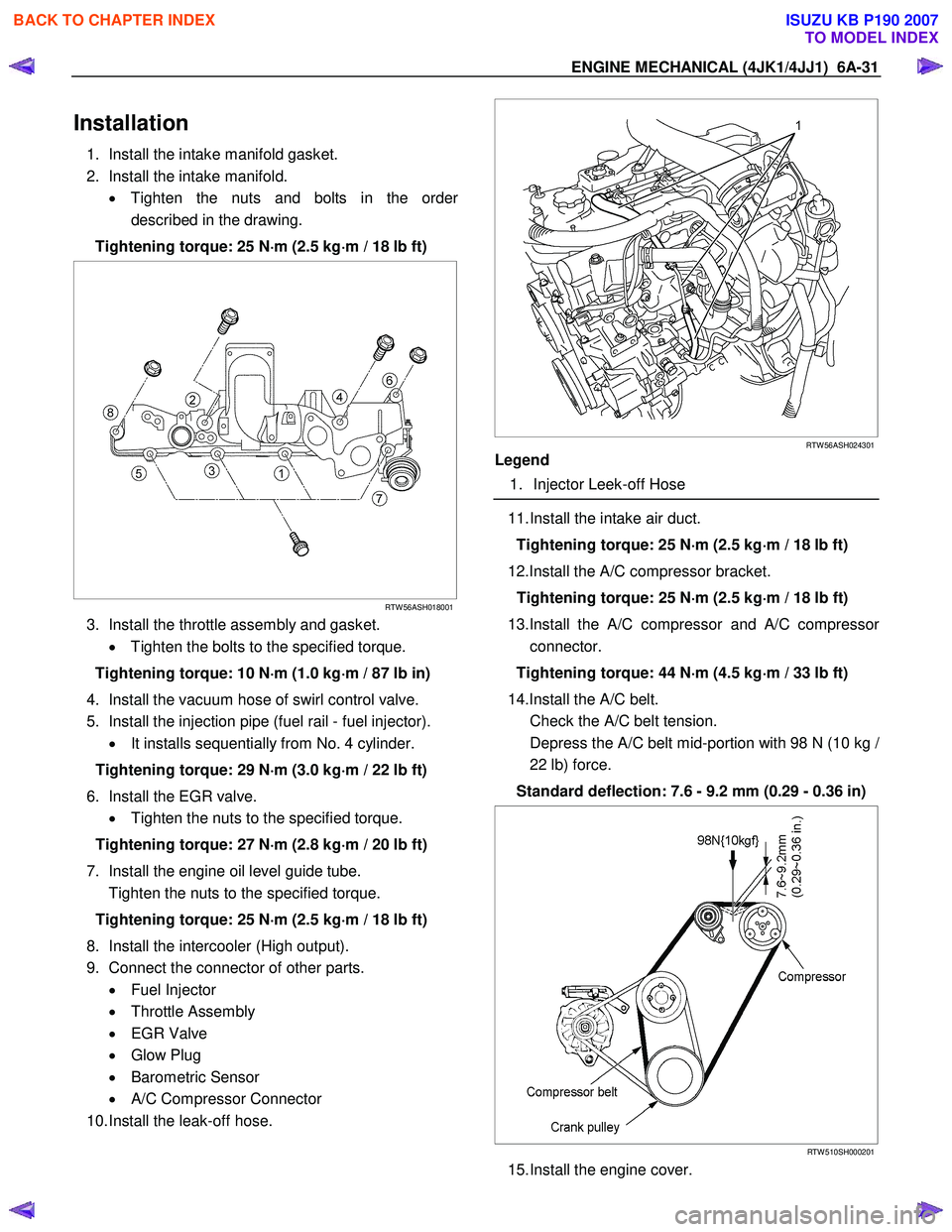
1. Install the intake manifold gasket.
2. Install the intake manifold. • Tighten the nuts and bolts in the orde
r
described in the drawing.
Tightening torque: 25 N ⋅
⋅⋅
⋅
m (2.5 kg ⋅
⋅⋅
⋅
m / 18 lb ft)
RTW 56ASH018001
3. Install the throttle assembly and gasket.
• Tighten the bolts to the specified torque.
Tightening torque: 10 N ⋅
⋅⋅
⋅
m (1.0 kg ⋅
⋅⋅
⋅
m / 87 lb in)
4. Install the vacuum hose of swirl control valve.
5. Install the injection pipe (fuel rail - fuel injector). • It installs sequentially from No. 4 cylinder.
Tightening torque: 29 N ⋅
⋅⋅
⋅
m (3.0 kg ⋅
⋅⋅
⋅
m / 22 lb ft)
6. Install the EGR valve. • Tighten the nuts to the specified torque.
Tightening torque: 27 N ⋅
⋅⋅
⋅
m (2.8 kg ⋅
⋅⋅
⋅
m / 20 lb ft)
7. Install the engine oil level guide tube.
Tighten the nuts to the specified torque.
Tightening torque: 25 N ⋅
⋅⋅
⋅
m (2.5 kg ⋅
⋅⋅
⋅
m / 18 lb ft)
8. Install the intercooler (High output).
9. Connect the connector of other parts. • Fuel Injector
• Throttle Assembly
• EGR Valve
• Glow Plug
• Barometric Sensor
• A/C Compressor Connector
10. Install the leak-off hose.
RTW 56ASH024301
Legend
1. Injector Leek-off Hose
11. Install the intake air duct.
Tightening torque: 25 N ⋅
⋅⋅
⋅
m (2.5 kg ⋅
⋅⋅
⋅
m / 18 lb ft)
12.Install the A/C compressor bracket. Tightening torque: 25 N ⋅
⋅⋅
⋅
m (2.5 kg ⋅
⋅⋅
⋅
m / 18 lb ft)
13.Install the A/C compressor and A/C compresso
r
connector.
Tightening torque: 44 N ⋅
⋅⋅
⋅
m (4.5 kg ⋅
⋅⋅
⋅
m / 33 lb ft)
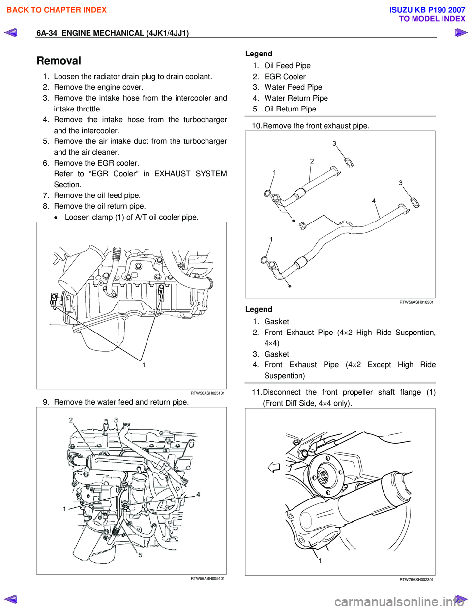
14.Install the A/C belt.
Check the A/C belt tension.
Depress the A/C belt mid-portion with 98 N (10 kg
/
22 lb) force.
Standard deflection: 7.6 - 9.2 mm (0.29 - 0.36 in)
RTW 510SH000201
15. Install the engine cover.
BACK TO CHAPTER INDEX
TO MODEL INDEX
ISUZU KB P190 2007
Page 1394 of 6020

6A-34 ENGINE MECHANICAL (4JK1/4JJ1)
Removal
1. Loosen the radiator drain plug to drain coolant.
2. Remove the engine cover.
3. Remove the intake hose from the intercooler and intake throttle.
4. Remove the intake hose from the turbocharge
r
and the intercooler.
5. Remove the air intake duct from the turbocharge
r
and the air cleaner.
6. Remove the EGR cooler.
Refer to “EGR Cooler” in EXHAUST SYSTEM Section.
7. Remove the oil feed pipe.
8. Remove the oil return pipe. • Loosen clamp (1) of A/T oil cooler pipe.
RTW 56ASH025101
9. Remove the water feed and return pipe.
RTW 56ASH005401
Legend
1. Oil Feed Pipe
2. EGR Cooler
3. W ater Feed Pipe
4. W ater Return Pipe
5. Oil Return Pipe
10. Remove the front exhaust pipe.
RTW 56ASH018301
Legend
1. Gasket
2. Front Exhaust Pipe (4 ×2 High Ride Suspention,
4 ×4)
3. Gasket
4. Front Exhaust Pipe (4 ×2 Except High Ride
Suspention)
11. Disconnect the front propeller shaft flange (1)
(Front Diff Side, 4 ×4 only).
RTW 76ASH002301
BACK TO CHAPTER INDEX
TO MODEL INDEX
ISUZU KB P190 2007
Page 1399 of 6020
ENGINE MECHANICAL (4JK1/4JJ1) 6A-39
9. Tighten the oil return pipe bolts and nuts to the
specified torque.
Tightening torque (Turbocharger side): 10 N ⋅
⋅⋅
⋅
m (1.0 kg ⋅
⋅⋅
⋅
m / 87 lb in)
Tightening torque (Crank case side): 25 N ⋅
⋅⋅
⋅
m (2.5 kg ⋅
⋅⋅
⋅
m / 18 lb ft)
10.Install the EGR cooler. • Refer to “EGR Cooler” in EXHAUST SYSTEM
section.
11. Install the heat protector. • Refer to “EGR Cooler” in EXHAUST SYSTEM
section.
12. Install the intake hose between the intercooler and the intake throttle (7).
13. Install the intake hose between the turbocharge
r
and the intercooler (9).
14. Install the intake duct between the turbocharge
r
and the air cleaner (8).
Tightening torque: 6 N ⋅
⋅⋅
⋅
m (0.6 kg ⋅
⋅⋅
⋅
m / 52 lb in)
15.Replenish the coolant.
BACK TO CHAPTER INDEX
TO MODEL INDEX
ISUZU KB P190 2007
Page 1406 of 6020
6A-46 ENGINE MECHANICAL (4JK1/4JJ1)
Exhaust Manifold (High Output)
Components
RTW 76FMF000101
Legend
1. EGR Cooler
2. EGR Cooler Gasket
3. EGR Cooler Gasket 5. Heat Protector
6. Exhaust Manifold
BACK TO CHAPTER INDEX
TO MODEL INDEX
ISUZU KB P190 2007