Page 1407 of 6020
ENGINE MECHANICAL (4JK1/4JJ1) 6A-47
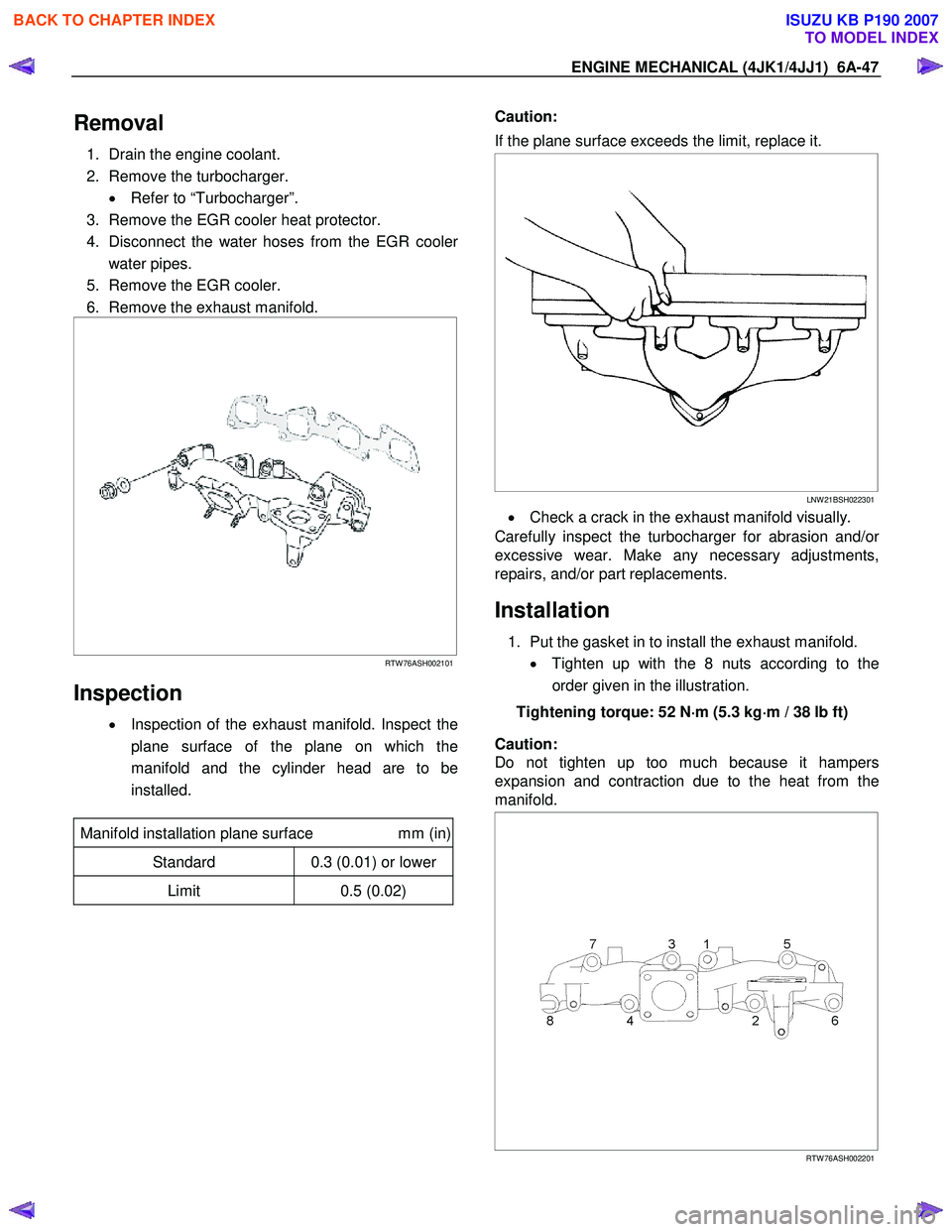
Removal
1. Drain the engine coolant.
2. Remove the turbocharger. • Refer to “Turbocharger”.
3. Remove the EGR cooler heat protector.
4. Disconnect the water hoses from the EGR coole
r
water pipes.
5. Remove the EGR cooler.
6. Remove the exhaust manifold.
RTW 76ASH002101
Inspection
• Inspection of the exhaust manifold. Inspect the
plane surface of the plane on which the
manifold and the cylinder head are to be
installed.
Manifold installation plane surface mm (in)
Standard 0.3 (0.01) or lower
Limit 0.5 (0.02)
Caution:
If the plane surface exceeds the limit, replace it.
LNW 21BSH022301
• Check a crack in the exhaust manifold visually.
Carefully inspect the turbocharger for abrasion and/o
r
excessive wear. Make any necessary adjustments,
repairs, and/or part replacements.
Installation
1. Put the gasket in to install the exhaust manifold.
• Tighten up with the 8 nuts according to the
order given in the illustration.
Tightening torque: 52 N ⋅
⋅⋅
⋅
m (5.3 kg ⋅
⋅⋅
⋅
m / 38 lb ft)
Caution:
Do not tighten up too much because it hampers
expansion and contraction due to the heat from the
manifold.
RTW 76ASH002201
BACK TO CHAPTER INDEX
TO MODEL INDEX
ISUZU KB P190 2007
Page 1408 of 6020
6A-48 ENGINE MECHANICAL (4JK1/4JJ1)
2. Install the EGR cooler.
• Install the gaskets.
• Install the EGR cooler.
• Temporary tightening order.
1 →2→ 3→ 4→ 5→ 6
• Fully tightening order.
3 →4→ 5→ 1→ 2→ 6
Tighten the nut and bolts to the specified torque.
Tightening torque: Nuts and bots 1-5: 27 N·m (2.8 kg·m / 20 lb ft)
Bolt 6: 52 N·m (5.3 kg·m / 38 lb ft)
6
543
1
2
RTW 76FSH000201
3. Install the water hoses to the EGR cooler water
pipes.
4. Heat protector.
Tighten the bolts to the specified torque.
Tightening torque: 25 N·m (2.5 kg·m / 18 lb ft)
RTW 76FSH000101
5. Install the turbocharger.
• Refer to “Turbocharger”.
6. Replenish the engine coolant.
BACK TO CHAPTER INDEX
TO MODEL INDEX
ISUZU KB P190 2007
Page 1435 of 6020
ENGINE MECHANICAL (4JK1/4JJ1) 6A-75
14. Disconnect the fuel injector connector (2).
15. Remove the fuel leak off hose (1).
RTW 76ASH000101
Note:
Do not reuse the fuel leak off hose clips.
16. Disconnect each connector. • Glow Plug
• EGR Valve
• Throttle Assembly
• Barometric Sensor
• W ater temperature sensor
• Camshaft Position sensor
17. Remove the harness bracket.
18. Remove the cylinder head cover.
Refer to “Cylinder Head Cover”.
19. Remove the EGR cooler heat protector.
20. Remove the EGR cooler water pipe.
21. Remove the EGR cooler.
22. Loosen the nuts of catalyst converter and
turbocharger.
RTW 56ASH006201
Legend
1. Catalyst Converter
2. Turbocharger
23. Remove the exhaust front pipe.
RTW 56ASH007701
Legend
1. Exhaust Front Pipe (4×2 High Ride Suspension, 4×4)
2. Exhaust Front Pipe (4×2 Except High Ride Suspension)
BACK TO CHAPTER INDEX
TO MODEL INDEX
ISUZU KB P190 2007
Page 1443 of 6020
ENGINE MECHANICAL (4JK1/4JJ1) 6A-83
Inspection
Make the necessary adjustments, repairs, and part
replacements if excessive wear or damage is
discovered during inspection.
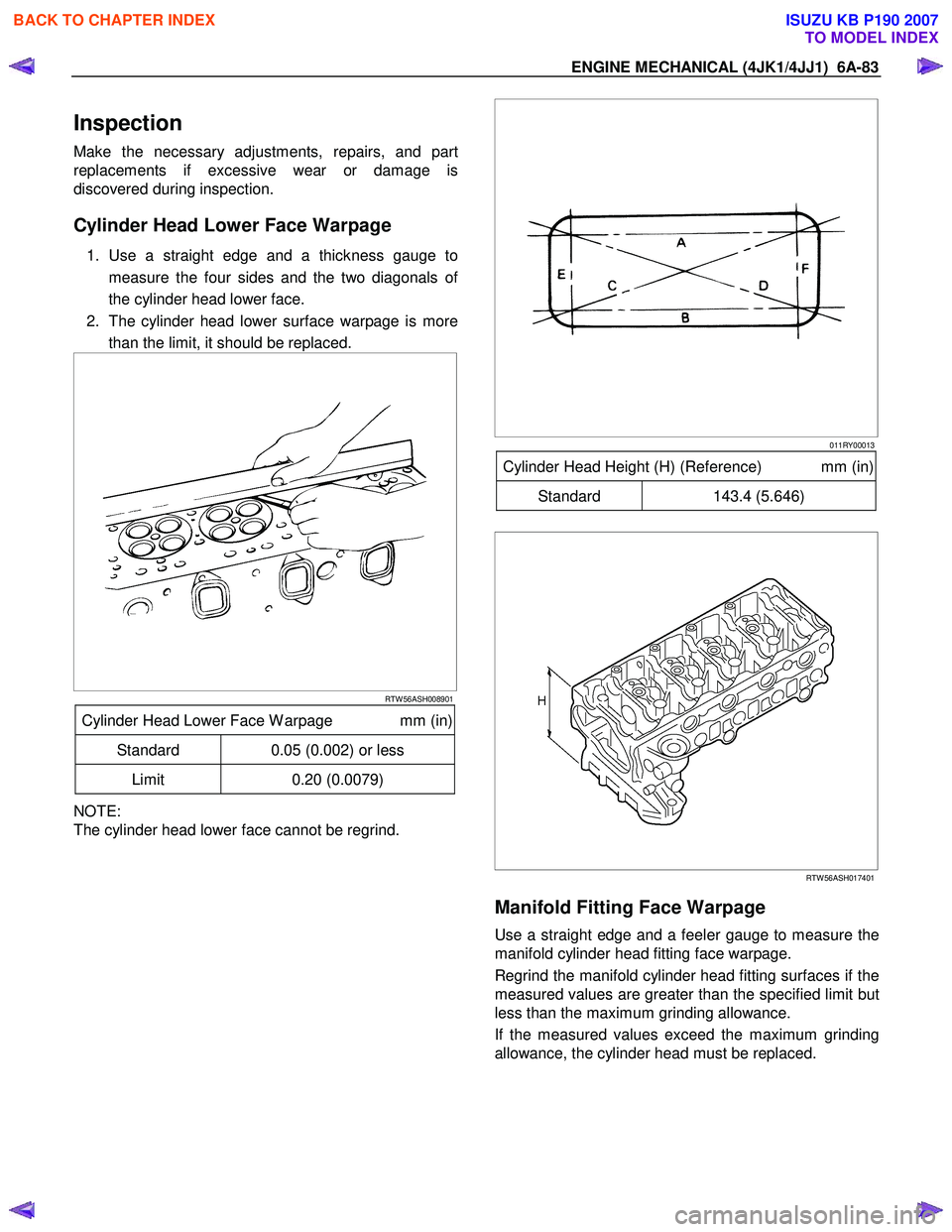
Cylinder Head Lower Face Warpage
1. Use a straight edge and a thickness gauge to
measure the four sides and the two diagonals o
f
the cylinder head lower face.
2. The cylinder head lower surface warpage is more than the limit, it should be replaced.
RTW 56ASH008901
Cylinder Head Lower Face W arpage mm (in)
Standard 0.05 (0.002) or less
Limit 0.20 (0.0079)
NOTE:
The cylinder head lower face cannot be regrind.
011RY00013
Cylinder Head Height (H) (Reference) mm (in)
Standard 143.4 (5.646)
RTW 56ASH017401
Manifold Fitting Face Warpage
Use a straight edge and a feeler gauge to measure the
manifold cylinder head fitting face warpage.
Regrind the manifold cylinder head fitting surfaces if the
measured values are greater than the specified limit but
less than the maximum grinding allowance.
If the measured values exceed the maximum grinding
allowance, the cylinder head must be replaced.
BACK TO CHAPTER INDEX
TO MODEL INDEX
ISUZU KB P190 2007
Page 1446 of 6020
6A-86 ENGINE MECHANICAL (4JK1/4JJ1)
014RY00027
Repair of the seat surface
• Remove carbon from the surface of the valve
insert seat.
• Use a seat cutter to minimize the scratch and
other roughness (15/45/75 degree-blade), thereb
y
returning the contact width to the standard value.
LNW 21BSH018201
Note:
Remove only scratches and roughness, and do not cut
the surface too much.
Use the free adjustment valve cutter pilot.
Do not let the valve cutter pilot waver inside the valve
guide.
Valve Seat Angle Degree
45
LNW 21BSH056101
• Attach compound in the valve insert seat.
• Insert the valve into the valve guide.
•
Attach compound on the valve seat surface, rotate
the valve and hit it lightly to grind it, and confirm
that it has even contact all round.
Note:
Remove compound completely after grinding.
LNW 21BSH031801
BACK TO CHAPTER INDEX
TO MODEL INDEX
ISUZU KB P190 2007
Page 1450 of 6020
6A-90 ENGINE MECHANICAL (4JK1/4JJ1)
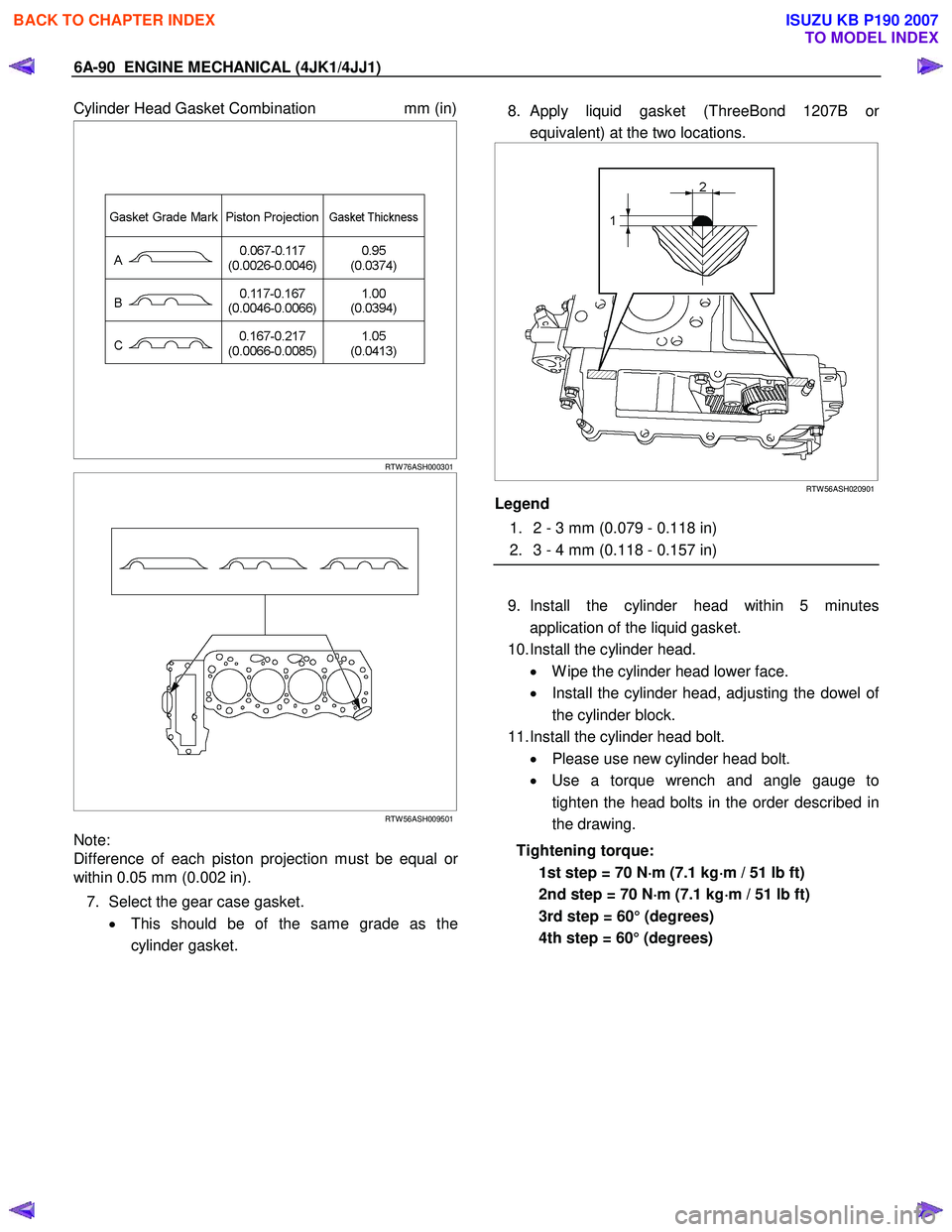
Cylinder Head Gasket Combination mm (in)
RTW 76ASH000301
RTW 56ASH009501
Note:
Difference of each piston projection must be equal o
r
within 0.05 mm (0.002 in).
7. Select the gear case gasket. • This should be of the same grade as the
cylinder gasket.
8. Apply liquid gasket (ThreeBond 1207B o
r
equivalent) at the two locations.
RTW 56ASH020901
Legend
1. 2 - 3 mm (0.079 - 0.118 in)
2. 3 - 4 mm (0.118 - 0.157 in)
9. Install the cylinder head within 5 minutes application of the liquid gasket.
10. Install the cylinder head. • W ipe the cylinder head lower face.
• Install the cylinder head, adjusting the dowel o
f
the cylinder block.
11. Install the cylinder head bolt. • Please use new cylinder head bolt.
• Use a torque wrench and angle gauge to
tighten the head bolts in the order described in
the drawing.
Tightening torque: 1st step = 70 N ⋅
⋅⋅
⋅
m (7.1 kg ⋅
⋅⋅
⋅
m / 51 lb ft)
2nd step = 70 N ⋅
⋅⋅
⋅
m (7.1 kg ⋅
⋅⋅
⋅
m / 51 lb ft)
3rd step = 60° (degrees)
4th step = 60° (degrees)
BACK TO CHAPTER INDEX
TO MODEL INDEX
ISUZU KB P190 2007
Page 1457 of 6020
ENGINE MECHANICAL (4JK1/4JJ1) 6A-97
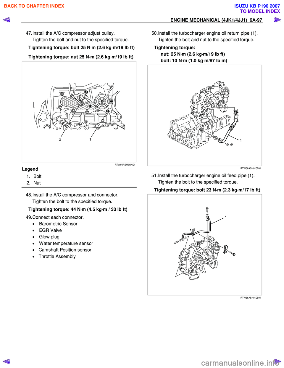
47. Install the A/C compressor adjust pulley.
Tighten the bolt and nut to the specified torque.
Tightening torque: bolt 25 N ⋅
⋅⋅
⋅
m (2.6 kg ⋅
⋅⋅
⋅
m/19 lb ft)
Tightening torque: nut 25 N ⋅
⋅⋅
⋅
m (2.6 kg ⋅
⋅⋅
⋅
m/19 lb ft)
RTW 56ASH010601
Legend
1. Bolt
2. Nut
48. Install the A/C compressor and connector.
Tighten the bolt to the specified torque.
Tightening torque: 44 N ⋅
⋅⋅
⋅
m (4.5 kg ⋅
⋅⋅
⋅
m / 33 lb ft)
49. Connect each connector. • Barometric Sensor
• EGR Valve
• Glow plug
• W ater temperature sensor
• Camshaft Position sensor
• Throttle Assembly
50. Install the turbocharger engine oil return pipe (1).
Tighten the bolt and nut to the specified torque.
Tightening torque: nut: 25 N ⋅
⋅⋅
⋅
m (2.6 kg ⋅
⋅⋅
⋅
m/19 lb ft)
bolt: 10 N ⋅
⋅⋅
⋅
m (1.0 kg ⋅
⋅⋅
⋅
m/87 lb in)
RTW 56ASH010701
51. Install the turbocharger engine oil feed pipe (1).
Tighten the bolt to the specified torque.
Tightening torque: bolt 23 N ⋅
⋅⋅
⋅
m (2.3 kg ⋅
⋅⋅
⋅
m/17 lb ft)
RTW 56ASH010801
BACK TO CHAPTER INDEX
TO MODEL INDEX
ISUZU KB P190 2007
Page 1458 of 6020
6A-98 ENGINE MECHANICAL (4JK1/4JJ1)
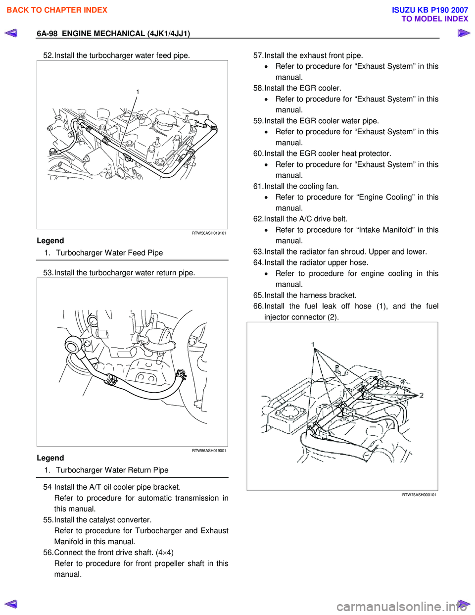
52. Install the turbocharger water feed pipe.
RTW 56ASH019101
Legend
1. Turbocharger W ater Feed Pipe
53. Install the turbocharger water return pipe.
RTW 56ASH019001
Legend
1. Turbocharger W ater Return Pipe
54 Install the A/T oil cooler pipe bracket.
Refer to procedure for automatic transmission in this manual.
55. Install the catalyst converter.
Refer to procedure for Turbocharger and Exhaust Manifold in this manual.
56. Connect the front drive shaft. (4 ×4)
Refer to procedure for front propeller shaft in this manual.
57. Install the exhaust front pipe.
• Refer to procedure for “Exhaust System” in this
manual.
58. Install the EGR cooler. • Refer to procedure for “Exhaust System” in this
manual.
59. Install the EGR cooler water pipe. • Refer to procedure for “Exhaust System” in this
manual.
60. Install the EGR cooler heat protector. • Refer to procedure for “Exhaust System” in this
manual.
61. Install the cooling fan. • Refer to procedure for “Engine Cooling” in this
manual.
62.Install the A/C drive belt. • Refer to procedure for “Intake Manifold” in this
manual.
63. Install the radiator fan shroud. Upper and lower.
64. Install the radiator upper hose. • Refer to procedure for engine cooling in this
manual.
65. Install the harness bracket.
66. Install the fuel leak off hose (1), and the fuel injector connector (2).
RTW 76ASH000101
BACK TO CHAPTER INDEX
TO MODEL INDEX
ISUZU KB P190 2007